Ad Lib Gold Developer Toolkit
A searchable reproduction of the Ad Lib Gold Developer Toolkit, Version 1.01 developer manual — with the complete Ad Lib Gold floppy-disk software preserved, decoded and browsable alongside it.
The Ad Lib Gold 1000/2000 was a 1992 16-bit sound card built around the Yamaha OPL3 (YMF262) FM synthesizer, a MMA digital-audio controller, an optional YM7128 (SP2) surround processor, a MIDI/game port and an optional SCSI interface. This toolkit documents the hardware, the bundled DOS applications, the DOS driver API, and the low-level register interface needed to program the card directly.
How this book is organized
| Section | What it covers |
|---|---|
| Release Notes | v1.01 addenda and driver caveats |
| Introduction | Copyright, licensing, contents |
| Chapter 2 - Quick Start | Installing hardware and software |
| Chapter 3 - Gold Hardware | Card layout, jumpers, connectors, surround module |
| Chapter 4 - Software Applications | Setup, test, mixer, jukebox, instrument/sample makers |
| Chapter 5 - DOS Software Drivers | Control, FM, Wave, Timer and MIDI driver APIs |
| Chapter 6 - Windows DLLs | Announced but not released in v1.01 |
| Chapter 7 - Low-Level Programming | MMA / OPL3 / mixer register reference |
| Appendix: GSS | Gold Sound Standard specification |
| Appendix: SP2 | YM7128 surround processor datasheet |
| Appendix D | List of installed files |
| Appendix E: Program Disks | The v1.00 end-user floppies as shipped — authentic images + files |
| Appendix F: Software (as installed) | The decoded 133-file \GOLD install tree |
| Appendix G: Developer SDK | Driver C/asm source, samples, toolkit + beta floppies |
| Appendix H: "Ad Lib Comp." format | Reverse-engineering the GOLD.CMP codec |
About this reproduction
This edition was produced with ocr.z.ai (GLM-OCR), which performed optical character recognition over the original scanned PDF, then rebuilding the result as an mdBook. The technical content is preserved as written in 1992; only structure and formatting were modernized:
- the six OCR fragments were reassembled into the manual's original chapters;
- OCR mojibake (for example
AdLib®) was repaired; - C function prototypes were placed in code blocks and register listings tidied;
- cross-links were added between the manual and the driver source in this repository.
Because it is a historical document, some names, phone numbers and addresses (such as the Ad Lib Developer Support line) are of purely historical interest. Text recovered by OCR may contain occasional transcription errors; consult the original scan where exactness matters.
The disk archive
Appendices E–H go beyond the manual and preserve the actual Ad Lib Gold software across every known release of 1992–93: the Beta v0.91b (March 1992), the end-user Program Disks v1.00 (1992), this Developer Toolkit v1.01, and the newest artifact — the standalone Windows 3.1 Mixer & Drivers v1.2 (July 1993). See the release timeline. Every file is kept byte-for-byte in its original DOS (CP437 / CRLF) encoding with a UTF-8 rendering alongside; the authentic 720 KB floppy images are included and were boot-sector-verified and malware-scanned before inclusion.
The end-user software shipped in a proprietary compressed container
(GOLD.CMP). Its format and LZ + static-Huffman codec were
reverse-engineered from the installer, so the
complete install trees — 133 files for v1.00 and 130 for the beta — could
be decoded and are browsable as installed. Decoding
is proven correct: the recovered CTRLDRV.EXE is byte-identical to the copy that
ships uncompressed on the disk.
This SDK lives in the
slartibardfast/adlib_goldrepository.
Release Notes (v1.01)
Addenda distributed with version 1.01 of the Ad Lib Gold Developer Toolkit.
AdLib®
GOLD
Developer Toolkit Reproduction
Ad Lib Gold Developer Toolkit Version 1.01 Release Notes
RL2DRV.EXE
The current version of the ROL2 playback TSR does not check for the presence of other drivers. The drivers used by RL2DRV.EXE must be loaded prior to executing this TSR.
When loading the ROL2 playback driver, the current directory must be the directory where the .SMP files are located.
SAMPL.EXE
The current version of the Sample Editor does not use the AD Lib Gold drivers. It uses linkable libraries that conflict with the drivers.
In order to execute the Sample Editor, all drivers must be removed from memory, otherwise the program may hang or display an "Insufficient Memory" message.
Disabling Interrupts when accessing the hardware
In order to avoid possible conflicts between applications that try to access the same hardware at the same time, it is recommended that interrupts be disabled when accessing the OPL3, the Control Chip or the MMA. This will avoid conflicts between applications, TSR programs and drivers that will be supplied with the Gold card in the future.
This procedure should be strictly adhered to for all software developed for the Gold card.
To insure that the interrupt flag status is not destroyed when re-enabling interrupts, the following procedure is recommended:
To disable interrupts:
pushf ; push flags, include interrupt flags
cli ; clear interrupts
To re-enable interrupts:
popf ; pop flag, includes interrupt flags
TSR Hotkey reconfiguration
The Mixer Panel TSR and ROL2 Playback TSR hotkeys can now be reconfigured from the SETUP.EXE application. Please the README.TXT file for more details on the changes that were made to SETUP.EXE, RL2DRV.EXE and MIXER.EXE
MIDI Driver, SCSI Driver, Windows DLLs
To be released
Introduction, Copyright & Licensing
Title page, copyright and licensing terms, and the top-level contents of the toolkit.
Ad Lib Gold
Developer Toolkit
Version 1.01
Copyright
This manual is protected by copyright law and may not be reproduced in whole or in part, whether for sale or not, without written consent from Ad Lib Inc. Under the copyright laws, copying includes translation into another language or format.
Ad Lib is a registered trademark of Ad Lib Inc.
Licensing Policy
Developers are authorized to incorporate the example source code provided with the Developper Toolkit into their products.
The no cost right to distribute Ad Lib Gold drivers provided with the Developer's Toolkit must be obtained through the Ad Lib Developer Support Department, at (418) 529-9676.
In order to ensure that third party applications operate in a consistent environment, we strongly recommend that developers contact the Ad Lib Developer Support Department.
Ad Lib Inc.
220 Grande-Allée East, Suite 850
Québec, QC, Canada G1R 2J1
50 Staniford Street, Suite 800 Boston, MA 02114
Copyright © 1992, Ad Lib Inc.
1st edition
ISBN 2-920858-32-7
Printed in Canada
-
Introduction
-
Quick Start and Evaluation Software
Installing the Hardware
Installing the Software
Using the Gold Card Evaluation Software
Adjusting the Volume
- Gold Hardware
3.1 Description of the Hardware
3.2 Getting Installed
3.3 Surround Sound Module
- Software Applications
4.1 Software Installation and Configuration
4.2 Test Program
4.3 Mixer Panel TSR
4.4 Juke Box Gold Music Playback Program
4.5 Instrument Maker Gold
4.6 Sample Maker
4.7 Surround Sound Editor
4.8 Batch File Utilities
4.9 ROL2 Playback TSR
- DOS Software Drivers
5.1 Interfacing DOS Drivers with Applications
5.2 DOS Control Features Driver
5.3 DOS FM Synthesis Driver
5.4 DOS Wave Driver
5.5 DOS Timer Driver
5.6 DOS MIDI Driver (To be released)
5.7 DOS SCSI CD-ROM Driver (To be released)
- Windows DLLs
(To be released)
- Low-level Programming
7.1 Mixer and Setup Features
7.2 FM Synthesis
7.3 Digital Input and Output (Digital Audio and MIDI)
Appendices
Appendix A: Gold Sound Standard
Appendix B: YM7128 - Surround Processor
Appendix C: Pin Out for Joystick-MIDI Connector
Appendix D: List of Installed Files
The Ad Lib Gold Developer Toolkit is a set of software applications, libraries, documentation and other information that will accelerate application support for the Ad Lib Gold series of cards.
The Developer Toolkit covers the following areas:
Quick Start and Evaluation Software
This section is for developers who want to try the software provided with the Gold Card and get a quick look at all programming possibilities. It summarizes the installation of the Gold card and briefly describes some of the available applications. The evaluation software provides tools for a variety of sound quality tests.
Gold Hardware
This section describes the physical layout of the Gold card, and the procedure for installing the card in your computer. It also provides a short description of the Surround Sound Module.
Software Applications
Describes the applications and TSRs that you can use with the Gold card. Some of these applications can be used to create FM sounds, digitized sounds, and Surround presets, that the developer can use in his/her applications.
Software Drivers
This section explains how your applications can interface with the memory-resident drivers. It also contains a complete function directory for each of the drivers. Sample source code is supplied on diskette to provide a better understanding of the use of the drivers and associated interface libraries. The MIDI driver, SCSI driver and Windows DLLs will be included with the next version.
Low-Level Programming
Details the I/O map of each of the hardware sections of the Gold Card. This section is intended for programmers who want to directly access the hardware, instead of using the software drivers.
Appendices
The appendices provide additional information on the Yamaha Gold Sound Standard, the Surround Processor chip (YM7128), a diagram covering the MIDI / Joystick connector, and a list of files copied to the hard drive during installation.
Please read the README.TXT file on DISK 1 for more information.
Chapter 2 - Quick Start and Evaluation Software
Installing the Gold card and software, and using the evaluation applications.
- Installing the Hardware
Installing the Gold Card 1
Connect the Other Peripherals 1
- Installing the Software
Read the README.TXT File 1
Install Gold Applications and Resources 2
Test Hardware 2
- Using the Gold Card Evaluation Software
Running Gold DOS Applications 2
- Adjusting the Volume
Quick Start and Evaluation Software
The Quick Start is intended for developers who want to have quick access to some of the evaluation programs provided with the Gold card.
Installing the Hardware
Installing the Gold card
-
Make sure that the on-board jumpers, the "Game port enable jumper", the "Port address jumper" and the "Dual joystick selector jumpers", are in the desired position.
-
Plug the Gold card into the computer in a free slot as far as possible from the video adapter card.
- NOTE: Certain cards, such as video adapters, produce high-frequency signals which can interfere with the sound quality of the sound card.
See "3.2: Getting Installed".
Connect the Other Peripherals
-
Plug headphones or external speakers into the main audio output of the card, or connect the output to the input of a stereo system.
-
Connect your microphone to the microphone input of the card.
-
Connect the output of your stereo source (CD player, CD-ROM drive, synthesizer or cassette player) to the stereo auxiliary input of the card, using a stereo cable.
-
Connect your joystick to the DB-15 game port of the card. If you plan to use the MIDI interface, connect your MIDI device with the Ad Lib adapter cable.
See "3.2: Getting Installed".
Installing the Software
Read the README.TXT File
We suggest that you examine the README.TXT file prior to installing the software. This file contains information on the latest program updates, and other necessary information.
- Insert Ad Lib diskette No.1 into the floppy drive, set the current drive to A (or B, depending on which drive you are using), and type the following command:
A:>type readme.txt
Install Gold Applications and Resources
- Run the Gold Setup Program by typing the following commands:
A: >ctrldrv
A:>setup
See "4.1: Software Installation and Configuration".
Test Hardware
Once installation is complete, run the Test program to verify that the Ad Lib Gold card is functioning properly.
- Go to the directory where you placed the Gold Test Program at installation and load this program by typing the following command:
testgold
See "4.2: Test Program".
Using the Gold Card Evaluation Software
Running Gold DOS Applications
Once the Gold hardware and software are installed, you can run any Ad Lib Gold application by proceeding as follows:
-
Set the current directory to the one where you placed the Gold programs during the installation process.
-
Load the Mixer Panel TSR program first, which serves to control the different sound parameters (balance, tone, volume, etc.), by typing the following command:
mixer
- Load the program you want by typing the corresponding command:
jukegold Juke Box Gold Music Playback Program
insgold Instrument Maker Gold Program
sample Sample Maker Program
surround Juke Box Gold Music Playback Program including the Surround Sound Editor
Note that the Juke Box Gold Music Playback Program offers on-line Help containing summarized information on how to operate the program and how to use the various features.
See Chapter 4 - Software Applications.
Adjusting the Volume
When running a program with the Gold card, you can adjust output volume at any time, without opening the Mixer Panel, using the following shortcuts:
Alt U For increasing output volume.
Alt D For decreasing output volume.
See "4.3: Mixer Panel TSR".
Chapter 3 - Gold Hardware
Card layout, connectors, jumpers, IRQ/DMA options, and the Surround Sound module.
3.1 Description of the Hardware 1
Functionality 1
Digital Recording 1
Digitized and Synthesized Sound Playback 1
MIDI Recording and Playback 2
Game Port 2
SCSI Interface 2
Layout of the Card 2
Bracket Connectors 2
On-board Connectors and Main Components 3
The On-board Jumpers 6
Available Interrupt Lines and DMA Channels 7
3.2 Getting Installed 9
System Requirements 9
Installing the Hardware 9
Hardware Configuration Settings 9
Removing the Computer Cover 11
Removing the Slot Cover 11
Installing the Gold Card 11
Connecting Other Peripherals 12
3.3 Surround Sound Module 15
Required Equipment 15
Installing the Surround Sound Module 15
Remove the Computer Cover 15
Remove the Sound Card 16
Attach the Surround Sound Module 17
Reinstall the Sound Card 17
Using the Surround Sound Option 18
Surround-based Applications 19
Using Surround Sound with Other Sound Sources 19
Programming the Surround Sound Module 20
Functionality
Your Ad Lib Gold Stereo Sound Adapter is a multifunction card with digital recording, playback of digitized and synthesized sounds, analog audio mixing, MIDI recording and playback, game port, and (for model Gold 2000) SCSI/CD-ROM interface.
Digital Recording
With the Ad Lib Gold card, you can record from:
-
A microphone, using Voice Pad or third party software;
-
An audio tape or a compact disk, using Voice Pad or third party software;
-
A telephone, using the optional add-on board contained in the Ad Lib PC Telephone Answering System.
Digitized and Synthesized Sound Playback
With the Gold card, you can play back:
-
Digitized sounds: The Gold card has two channels for digitized sounds. These channels can be used in a variety of ways, such as for voice notes with the Voice Pad program, percussion sounds in the Juke Box Gold songs, or third party software using stereo music or music with voiceover.
-
Synthesized sounds: The Gold card has a 20-voice FM synthesizer which is used for Juke Box Gold songs and third party software music.
The sound capability of the Gold card also features:
-
Audio mixing: The internal analog mixer of the Gold card controls the volume of various audio sources, through programming, such as within third party software, or manually using the Mixer Panel (see "Mixer Panel TSR" section).
-
Volume control: The output volume of the Gold card is software controlled (see "Mixer Panel TSR").
-
Tone control: Bass and treble controls are software controlled (see "Mixer Panel TSR").
MIDI Recording and Playback
The MIDI (Musical Instrument Digital Interface) interface of the Gold card allows MIDI files to be recorded and played back using a MIDI adapter cable, any external MIDI instrument and an Ad Lib Gold supporting sequencer program.
Game Port
The Ad Lib Gold card allows a standard IBM compatible joystick to be connected.
SCSI Interface
The Gold card SCSI interface (optional with Gold 1000 and included on-board with Gold 2000) allows a CD-ROM drive or any SCSI type peripheral to be connected.
Layout of the Card
Bracket Connectors
Ad Lib Gold Stereo Sound Adapters have three 1/8" connectors and one DB-15 connector on the support brackets, as shown in the diagrams (Figures 1 and 2).
These connectors are:
-
The microphone input (No.7), for sampling and/or mixing with other audio sources.
-
The stereo auxiliary input (No.8), for connecting an external source such as a CD or cassette player, a synthesizer or any audio source, in order to sample and/or mix with other audio sources.
-
The main stereo audio output (No.9), for connecting to standard headphones, bookshelf speakers or a stereo system.
-
The Game Port/MIDI connector (No.10), for using a standard PC joystick and/or a MIDI device. This requires an optional MIDI cable adapter available from Ad Lib.
On-Board Connectors and Main Components
Ad Lib Gold Stereo Sound Adapters have on-board connectors to support many different options and internal/external devices. These connectors are shown in the diagrams (Figures 1 and 2).
These connectors are:
-
On model Gold 2000, the SCSI port connector (Figure 2: No. 22), to connect a SCSI device, such as a CD-ROM, hard disk or tape backup drive. A 50-pin flat cable is provided for connecting an internal device. Cabling for connecting an external device is optional.
-
On model Gold 1000, the SCSI option connectors (Figure 2: No.20), to snap on a SCSI piggyback board.
-
The Surround Sound option connectors (No.1), to connect a Surround Sound Module. This module is used to provide stereo and depth enhancements.
-
The telephone option connector (No.2), to connect a telephone line interface add-on board. This board allows the Ad Lib Gold card to be connected to a standard telephone line and provides access to various functions, such as creating a completely digital telephone answering system capable of leaving
personalized messages for callers and recording and playing back messages left by callers directly to and from a hard disk, or creating an interactive automated telephone routing and database navigation station. It is also capable of automated dialing.
- The internal stereo auxiliary input (No.4), to connect a PC internal audio device (such as an internal CD-ROM drive) for direct input. This connector is in parallel with and has exactly the same functions as the external stereo auxiliary input connector on the support bracket.
NOTE: It is not recommended to use both the external and internal stereo auxiliary input at the same time, because this will decrease the volume of the auxiliary audio source.
- The PC speaker connector (No.3), to connect the signal of the PC's internal speaker directly to the Ad Lib Gold card, so that it is mixed with the other audio signals on the card and can be heard through the headphones or speakers.
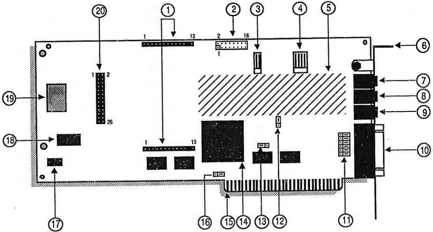
Figure 1: Gold 1000 diagram
-
Surround Sound option connectors
-
Telephone option connector
-
PC speaker connector
-
Internal stereo aux. input
-
Power amp and analog mixer
-
Bracket
-
Microphone input (mono)
-
Stereo aux. input
-
Main audio output
-
Game port/MIDI DB-15 connector
-
Dual joystick selector jumpers (JP2-7)
-
Port address jumper (JP8)
-
Control chip reset jumper (JP9)
-
Custom control VLSI chip
-
Bus connector
-
Game port enable jumper (JP1)
-
16-bit FM DAC
-
Professional FM synthesis chip
-
Sampling 12-bit DAC and MIDI chip
-
SCSI option connector
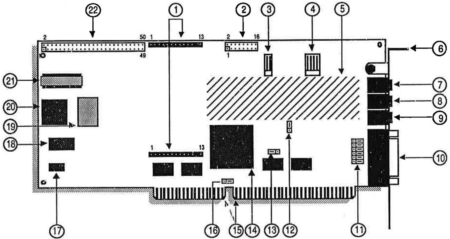
Figure 2: Gold 2000 diagram
-
Surround Sound option connectors
-
Telephone option connector
-
PC speaker connector
-
Internal stereo aux. input
-
Power amp and analog mixer
-
Bracket
-
Microphone input (mono)
-
Stereo aux. input
-
Main audio output
-
Game port/MIDI DB-15 connector
-
Dual joystick selector jumpers (JP2-7)
-
Port address jumper (JP8)
-
Control chip reset jumper (JP9)
-
Professional FM synthesis chip
-
16-bit FM DAC
-
Custom control VLSI chip
-
Bus connector
-
Sampling 12-bit DAC and MIDI chip
-
SCSI chip
-
Game port enable jumper (JP1)
-
SCSI terminator resistor
-
SCSI cable connector
The On-board Jumpers
To make it easier to configure the Ad Lib Gold card, we have made the Interrupt lines (IRQ) and DMA channels software selectable, thereby keeping the amount of jumpers to a minimum. The four remaining jumper sets are the game port enable jumper (JP1), the dual joystick selector jumpers (JP2-7), the port address change jumper (JP8), and the Control chip reset jumper (JP9).
The Gold card jumpers are the following:
- Game port enable jumper (No.16) This jumper lets the user enable/disable Ad Lib Gold's on-board game port interface. The interface should be disabled in cases where the user already has a standard PC game port interface inside his/her PC, to avoid conflicts.
Jumper setting is shown here:
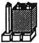
Game port enabled
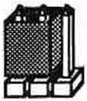
Game port disabled
Figure 3: Game port jumper enabling
| · | NOTE: The jumper is factory set to the game port enabled position. |
- Dual joystick selector jumpers (No.11) These jumpers let the user change the factory-set "joystick plus MIDI" option (all jumpers on the bracket side) to the "two joysticks without MIDI" option (all jumpers on the opposite side). All jumpers in this selector must be changed to the same position, as shown in the following illustrations.
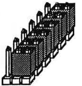
Single joystick with MIDI option (factory-set)
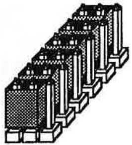
Dual joystick option
Figure 4: Dual joystick jumper selection
Port address jumper (No. 12)
This jumper lets the user choose a single or double port address for the Gold card. The Ad Lib Gold card addresses can be assigned by software programming. The default port address of the Gold card is 388H and can be changed by software in cases where another card inside the PC uses the same address, in order to avoid conflicts. In the case where the software cannot recognize the programmed address, the port address jumper is used to force the Gold card into answering at both the programmed address and at the default factory address 388H.
NOTE: The port address jumper is factory set to single port address position (jumper plugged on the two pins on the bracket side) which enables only one port address to be used at a time.
The port address jumper can be changed to double port address position (jumper plugged on the side opposing the bracket) which forces the default address 388H to be used in conjunction with any other user-defined one.
- Control chip reset jumper (No.13) This jumper is used where the programmed configuration of the control chip is lost. In some cases, losing the configuration can cause the card to use addresses that are already in use by other hardware. Removing
the control chip reset jumper disables certain functions of the Gold card that could cause hardware conflicts. Once the jumper is removed, reconfigure the Gold card to the factory preset values by issuing the following command:
setup /R
Once the Gold card is reconfigured, replace the control chip reset jumper.
Available Interrupt Lines and DMA Channels
-
There are four software selectable interrupt lines (IRQ 3,4,5 and 7) on the Gold 1000, and four additional choices on the Gold 2000 (IRQ 10,11,12 and 15).
-
DMA channels 1,2 and 3 are software selectable on the Gold 1000, and DMA channels 0,1,2, and 3 are software selectable on the Gold 2000.
System Requirements
To use the Ad Lib Gold card and the Gold software, you need the following:
- For the Gold 1000: an IBM PC, XT, AT (286), 386, 486 compatible computer, PS/2 Model 25 and 30, or Tandy 1000 (except EX/HX), a disk drive (1.2 MB 5 1/4" or 720 KB 3 1/2") and 640K of RAM.
For the Gold 2000: an IBM AT (286), 386 and 486 compatible computer, a disk drive (1.2 MB 5 1/4" or 720 KB 3 1/2") and 640K of RAM.
-
A hard disk.
-
Graphics adapter, any model.
-
PC/MS-DOS 3.0 or higher.
-
Headphones, an external speaker or a home stereo system.
-
A microphone.
Installing the Hardware
We suggest that you read this section thoroughly before you begin. This will familiarize you with the standard installation procedure.
These instructions are for installing your Ad Lib Gold card in your computer. We recommend that you read the owner's manual supplied with your computer for instructions specific to your model of computer.
Hardware Configuration Settings
To install the Ad Lib Gold card, there are two types of configuration settings: hardware settings and software settings. The Gold card uses software for most of the configuration settings (see the sections on installation and configuration below). Only three hardware settings, made with jumpers, are necessary: game port enabling/disabling, dual joystick selection and port address. These should be made before installing the Gold card in your computer.
To Set Game Port Enable/Disable Jumper
The game port enable/disable jumper lets the user enable or disable Ad Lib Gold's on-board game port interface. The interface should be disabled in cases where the user already has a standard PC game port interface inside his/her PC, in order to avoid conflicts. To obtain the desired setting:
-
Locate the jumpers for the game port enable/disable setting (refer to Figure 1 or 2, No.15).
-
If your computer does not have a game port, make sure that the jumper is over the two left pins as shown in Figure 3. This jumper is factory set in the game port enabled position.
-
If your computer has a game port, unplug the jumper from the two left pins and replug it onto the two right pins as shown in Figure 3.
To Set Dual Joystick Selector Jumpers
The dual joystick selector jumpers let the user change the factory-set "joystick plus MIDI" option to the "two joysticks without MIDI" option. All jumpers in this selector must be changed to the same position, as shown in Figure 4. To obtain the desired setting:
-
Locate the dual joystick selection jumpers (refer to Figure 1 or 2, No.11).
-
If you wish to use the Gold card's game port in the "single joystick with MIDI option", leave the jumpers in the factory-set position (i.e. plugged into the bracket side of the card) as shown in Figure 4.
-
If you want to use the Gold card's game port in the "dual joystick option", unplug all six jumpers and replug them onto the jumpers, as shown in Figure 4.
To Set Port Address Jumper
The port address jumper lets the user choose a single or double port address for the Gold card. The default port address of the Gold card is 388H. It can be changed with the Setup program in cases where another card inside the PC uses the same address as the Ad Lib card.
The port address jumper is factory set to the single port address position which enables only one port address to be used at a time. These port addresses can be modified by software. It can be changed to double port address position, which forces the default address 388H to be used in conjunction with any other.
To obtain the desired setting:
-
Locate the jumpers for the port address setting (refer to Figure 1 or 2, No. 12).
-
If you wish to use only one port address at a time (388H or any other), make sure that the jumper is over the two upper pins. This jumper is factory set in the single port address position.
-
If you wish to force the default port address 388H to be used in conjunction with another one, unplug the jumper from the two upper pins and replug it onto the two lower pins.
Removing the Computer Cover
-
Switch off the computer.
-
Disconnect the power cord and all peripheral devices and cables.
-
Set the computer on a flat, clear surface.
-
Remove the mounting screws that hold the computer cover.
-
Remove the computer cover.
Removing the Slot Cover
- Choose a free slot as far as possible from the video adapter card.
NOTE: Certain cards, such as video adapters, produce high-frequency signals which can interfere with the sound quality of the sound card.
-
Remove the screw that holds the slot cover in place.
-
Lift the slot cover to remove it.
! WARNING: If a screw falls into the computer, you absolutely must remove it before switching your system back on. If a metal object is left loose inside the casing of your computer, It may cause a short circuit that will damage your system.
Installing the Gold Card
-
Place the card immediately above the slot without inserting it into the socket.
-
Make sure that the bracket is inserted in the groove previously occupied by the slot cover.
-
Press the card down into the socket.
-
Put the card's bracket screw back on and tighten it.
-
Put the computer cover back on and tighten the screws.
-
Reconnect the power cord and other cables.
Connecting Other Peripherals
The card is equipped with jacks and plugs for connecting various peripherals. These allow devices to be connected to: stereo audio output, microphone input, line-level stereo audio input, MIDI/game port, PC internal speaker and SCSI port (Gold 2000 model only).
Audio Output
The Gold card is equipped with three 1/8" jacks for connecting audio equipment. The main audio output is the lowermost of the three jacks, located above the DB-15 connector (refer to Figure 3 or 4). This jack can be connected to headphones, external speakers or a stereo system using stereo adapters and cables. Model Gold 2000 comes with a cable. To avoid distortion when connecting to a stereo system, connect the card to an auxiliary-type input.
Microphone Input
The microphone input is the uppermost of the three audio jacks on the card's bracket (refer to Figure 3 or 4). This connector lets the audio signal from a standard microphone be mixed with other audio sources or to be used as a source for sampling sounds.
Stereo Auxiliary Input - External Connector
The external stereo auxiliary input connector is located in the center of the three audio jacks on the card's bracket (refer to Figure 3 or 4). This connector lets audio signals from a stereo source (such as a CD player, CD-ROM drive, synthesizer or cassette player) be mixed with the other audio sources or to be used as a source for sampling sounds.
WARNING: To avoid distortion, it is important to keep the audio level of the device you are connecting to this input Jack at low volume and to adjust the volume using the software controls explained in the next section. Also, make sure that you are using the auxiliary output of the device you are connecting to the card, instead of using the speaker output which would overload the card's amplifier.
Stereo Auxiliary Input - Internal Connector
As mentioned in the "Description of the Hardware: Layout of the Card" section, there is an internal connector (see No. 4 in Figure 1 or 2) for connecting the audio output of an internal CD-ROM drive. This connector is electrically in parallel with the external stereo auxiliary input connector. Thus, to obtain good sound results, you may only use one of these at a time.
MIDI/Game Port
The Ad Lib Gold card features a standard DB-15 connector at the bottom of its supporting bracket (refer to Figure 1 or 2). This connector lets the user
connect one of the following three options:
-
An IBM compatible joystick.
-
A MIDI device. (This requires an adapter cable.)
-
Dual joystick. (This requires a special adapter which is usually supplied by the joystick manufacturer. See Figure 4 for related jumper settings.)
Ad Lib Gold Stereo Sound Adapters have an expansion connector for an optional plug-in module capable of adding a "surround" sound effect to the audio output of the card. This effect can range from stereo depth simulation to artificial reverberation and echo.
The Ad Lib Surround Sound Module is a piggyback card and so does not require its own dedicated slot.
Required Equipment
To use the Ad Lib Surround Sound Module, you need the following equipment:
-
An Ad Lib Gold Stereo Sound Adapter: Gold 1000 or Gold 2000.
-
For the Gold 1000: an IBM PC, XT, AT (286), 386, 486 compatible computer, PS/2 Model 25 and 30, or Tandy 1000 (except EX/HX), a disk drive (1.2 MB 5 1/4" or 720 KB 3 1/2") and 640K of RAM.
For the Gold 2000: an IBM AT (286), 386 and 486 compatible computer, a disk drive (1.2 MB 5 1/4" or 720 KB 3 1/2") and 640K of RAM.
-
A hard disk.
-
An operating system: PC/MS-DOS 3.0 or later.
-
A graphics adapter (monitor).
-
Headphones, external speaker(s) or home stereo system.
Installing the Surround Sound Module
To install the Surround Module onto the Ad Lib Gold card, proceed as follows:
Remove the Computer Cover
-
Switch off the computer, disconnect the power cord, and disconnect all peripheral devices and cables connected to the computer.
-
Set the computer on a flat, clear surface.
-
Remove the mounting screws at the back of the computer (consult your hardware user's guide).
-
Remove the computer cover (consult your hardware user's guide).
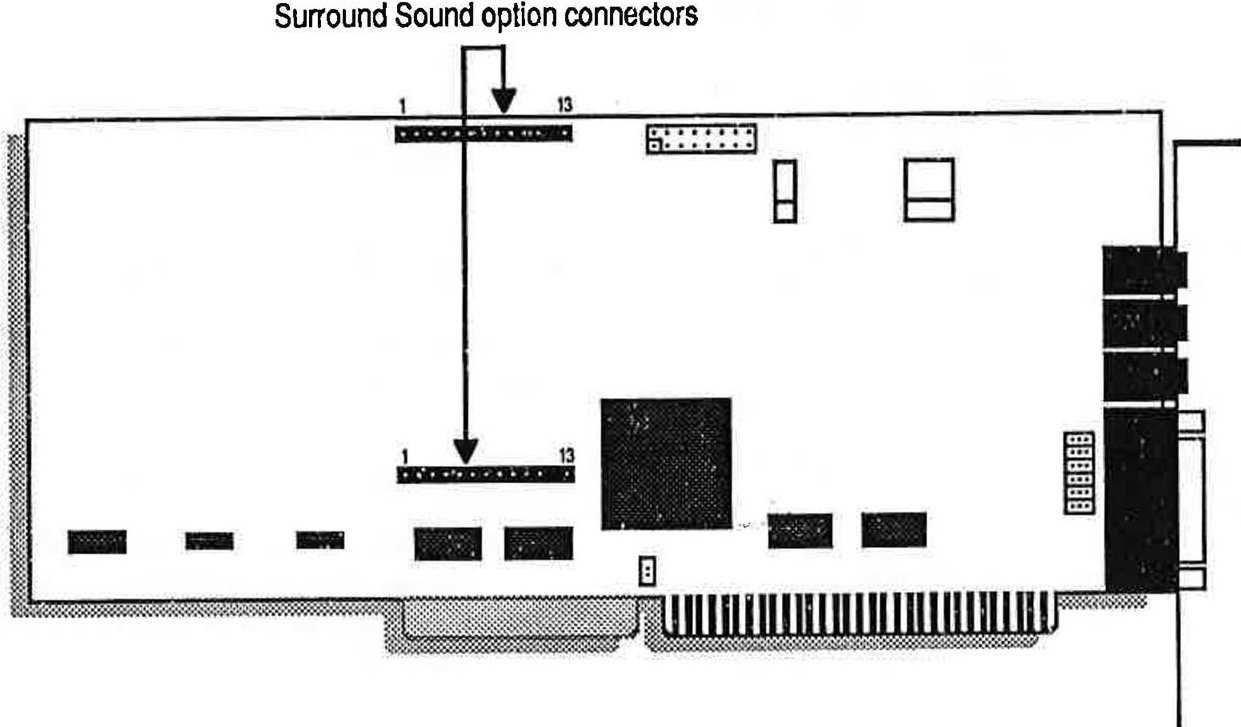
Figure 1: Location of the Surround Sound option sockets on the Ad Lib Gold 1000 and 2000 cards
Remove the Sound Card
! WARNING: Users should ground themselves before handling the card. Please read the manual before beginning Installation.
-
Remove the sound card bracket screw.
-
Take the sound card out of the computer and place it on a flat surface so that it is positioned as in Figure 1.
Attach the Surround Sound Module
-
Locate the Surround Sound option sockets on the sound card (see Figure 1).
-
Place the module connector pins immediately above the socket holes on the sound card.
-
Make sure that the No.1 pins of the module line up with the No.1 holes of the sound card. (If properly aligned, the Ad Lib logo will be in an upright position.)
-
Simultaneously press both ends of the module firmly into the card sockets (see Figure 2).
! WARNING: The module only fits in one way, since both No.12 pins are missing and the No.12 socket holes are stoppered. Do not force the module in if you feel resistance; it may be Incorrectly positioned.
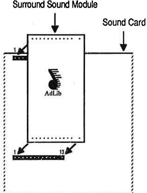
Figure 2: Attaching the Surround Sound Module
Reinstall the Sound Card
-
Place the card immediately above the slot without inserting it into the socket.
-
Make sure that the bracket is inserted in the groove previously occupied by the slot cover.
-
Press the card down into the socket.
-
Put the card's bracket screw back on and tighten it.
-
Put the computer cover back on and tighten the screws.
-
Reconnect the power cord and other cables.
Using the Surround Sound Option
Once your module is connected to the sound card, the Surround Sound option is ready to use.
Ad Lib's control software offers the user a choice of various pre-programmed audio enhancements that create totally new, compelling effects. To use the Surround Sound option, simply proceed as follows:
-
Load the Ad Lib Gold Mixer Panel Utility (see the Gold card user guide for complete information on the Mixer Panel).
-
Activate the Mixer Panel. Alt - M are the default activation keys, but you may change this combination with the "Keys" window of the Mixer Panel.
-
Press the key when in the Mixer Panel main window to open the Surround Features control window (see Figure 3).
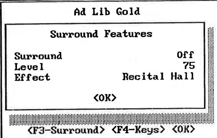
Figure 3: Mixer Panel Surround Features window
| * NOTE: If the Surround Sound Module is not installed, or not correctly installed, the program will display the message:"OPTION NOT INSTALLED" and changes you make to the parameters will have no effect. |
- Using the arrow keys, select (with and and set (with and the Surround Sound option parameters:
Surround
A toggle On/Off allows the Surround Sound option to be enabled or disabled. The default setting is Surround Off. The Mixer Panel also allows you to use a combination of keys for enabling and disabling the surround sound effect. The default combination is Alt- S, but you may change this combination with the "Keys" window of the Mixer Panel.
Level
Sets the volume level of the surround sound effect.
! WARNING: Do not set the level of the surround sound effect too high, because it may result in distortion in some cases. It is advisable to increase the level by only a few units at a time.
Effect
Sets the type of surround sound effect you want from among the presets.
<OK> ( or Esc )
Closes the Surround Features control window, then the main Mixer Panel window with the changes you made in the parameter settings.
Surround-based Applications
Software does not have to be specially written to take advantage of the Ad Lib Surround Sound module. The module will instantly enhance any music and sound program written with Ad Lib sound support. Nevertheless, software developers can program surround sound effect changes within their application for contrast and drama.
Using Surround Sound with Other Sound Sources
Besides sound and music software, any audio source mixed with the Gold card can take advantage of Surround effects. The internal analog mixer allows you to blend FM and sampling sounds, with live mike sounds, a CD or cassette player, a synthesizer, a CDROM drive, etc. Simply connect your instrument, choose the surround effect you want and set the output balance for these sound sources with the Ad Lib Gold Mixer Panel Utility. Please refer to your Ad Lib Gold Stereo Sound Adapter and DOS Software user guide for details on the mixer and Mixer Panel.
It is also possible to add surround sound effects to regular tape recordings. To do so, simply connect the audio source (microphone, synthesizer, etc.) to the input connector of the Gold card, and the output of the card to the tape input of your tape recorder.
Programming the Surround Sound Module
If you do your own programming, it is possible to program the Surround Sound Module with the Ad Lib Gold Programmer's Manual. It shows you how to program your own presets and dynamic surround changes, to add extra contrast and drama to your Ad Lib Gold Sound applications.
Chapter 4 - Software Applications
Setup, the hardware test program, the Mixer Panel TSR, Juke Box Gold, Instrument Maker, Sample Maker and the Surround Sound Editor.
- 4.1 Software Installation and Configuration
Using the Setup Program 1
Configuration Environment Variable 3
- 4.2 Test Program
Testing the Hardware 5
Preparing the Test Program 5
Loading the Test Program 5
To Continue the Test 5
To Cancel the Test and Exit the Program 6
Choosing Test Options 6
- 4.3 Mixer Panel TSR
Loading the Mixer Panel TSR 7
Activating the Mixer Panel 8
Using the Mixer Panel 8
Sound Parameters 8
Sub Mixer 9
Surround Features 10
ALT-SHIFT Keys (Short Cuts) 11
Closing the Mixer Panel 12
Removing the Mixer Panel TSR 12
- 4.4 Juke Box Gold Music Playback Program
Loading Juke Box Gold 13
Selecting Songs 14
Creating a Selection of Songs 14
To Remove Songs from the Selection 14
Playing Music 14
To Play Songs 14
To Stop Music Playback 14
To Pause and Resume Music Playback 14
To Scan Songs 15
Adjusting the Sound 15
To Adjust the Volume, Bass or Treble 15
To Set the Stereo/Mono Option 15
Asking for Help 15
Exiting the Program 16
Using the ROL2 Playback TSR 16
4.5 Instrument Maker Gold 17
Loading Instrument Maker Gold 17
Using Menu Commands 17
F5 File 17
F6 Options 17
F7 Document 18
Editing FM Instrument Sounds 18
4.6 Sample Maker 19
Loading Sample Maker 19
Using Menu Commands 19
F5 File 19
F6 Edit 19
F7 Sampling 20
F8 Options 20
Important Warnings for this Development Version of Sample Maker 21
Sampling Rate Limitations 21
Sampling Length Limitation 21
Scope Mode 21
Graphic Display in Different PCM Format 21
4.7 Surround Sound Editor 23
Ad Lib Surround Sound Editor 23
Technical Features 23
Opening the Surround Sound Editor 23
Using the Surround Sound Editor 24
Channel Line Attenuation Sections 25
Global Level and Feedback Parameter Section 25
Filter Parameter Section 25
Global Delay Line Parameter Section 25
Editing Surround Sound Presets 26
Using Menu Commands 26
File Menu 26
Panel Menu 27
Closing the Surround Sound Editor 27
4.8 Batch File Utilities 29
ROL2 Playback Utility 29
Digitized Sound Playback Utility 29
4.9 ROL2 Playback TSR 31
Using the ROL2 Playback TSR 31
ROL2 Playback TSR Data Files 31
ROL2 Playback TSR Options 32
The running and using of the Ad Lib Gold card drivers and programs require hard disk space of 3 megabytes. They must be installed onto the hard disk following a precise procedure. For this purpose, the Gold software package includes a special Setup Program. This program enables you to install the drivers and all associated programs, and to configure your Ad Lib Gold card.
Using the Setup Program
The Ad Lib diskettes are not copy-protected. We recommend that you make a back-up copy before installing Gold software. Put the originals away in a safe place. This way, if a diskette is lost or damaged, you will have a replacement. We suggest that you use the DISKCOPY command. (For all details concerning the copy commands, refer to your DOS manual.)
To Load the Setup Program
To load the Ad Lib Gold Setup Program:
-
Insert the first Ad Lib diskette into the floppy drive.
-
Set the current drive to A (or B, depending on the drive you are using).
-
Type the following commands:
A: >ctr1drv
A:>setup
When the program opens, a window entitled "Installation Notes" introduces you to the Setup Program and its basic commands. Two main buttons are displayed at the bottom of each screen: <Cancel> and <Continue>.
Activating the <Continue> button in the Installation Notes introductory screen makes the Setup Program open the Main Selection menu (see Figure 5).
This menu lets you choose and access the three following submenus:
-
Copy programs and drivers to hard disk
-
Configure the card and drivers
-
Leave the Installation Program
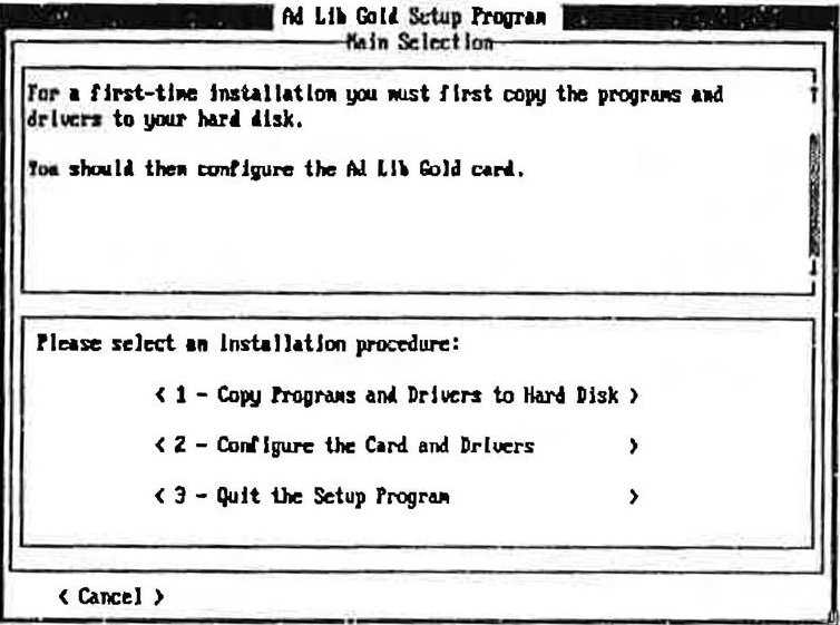
Figure 5: Setup Program's Main Selection menu
To Cancel the Setup Process
At any moment, you can interrupt the setup process by clicking on the <Cancel> button at the lower left corner of the screen, or by pressing the Esc key. Doing this will abort the setup and cancel the steps you have made. The changes you made are not saved in permanent memory on the card. When you reboot your system, these changes will not be restored. So, if you have a problem after making a change, just reboot your system.
NOTE: Certain elements cannot be reversed and will remain installed, such as copied files. To cancel the entire operation, it is necessary to re-run the Setup Program and reverse the corresponding steps, or delete the copied files. See Appendix A for a list of the installed files.
To Continue the Setup Process
In the setup process, activating the <Continue> button lets you close the current dialog box and access the next step. Doing this will initiate the changes you made in this dialog box, if there were any.
To Answer Program Questions
During each step of the setup procedure, you will be asked to choose between different options or to enter answers in edit fields. The program suggests an answer that will be correct in most situations. You can use this default, or enter your own answer.
Configuration Environment Variable
A special environment variable, called "GOLD" is used by the software to recognize the base address of the Gold card. When the card is relocated by the Setup program, the program automatically modifies the environment variable in the AUTOEXEC.BAT file.
To change the GOLD environment variable, type the following command, which should be preferably put in the AUTOEXEC.BAT file:
SET GOLD=xxx
When the Gold environment variable is not defined, the programs assume a default base address of 388H.
Where xxx is the hexadecimal value of the Gold card base address (Control chip address).
Testing the Hardware
The Ad Lib Gold Test Program, which is supplied with the Gold software, enables you to verify that the Gold card is functioning properly. These tests are not only used to test the Ad Lib hardware, but also to test the connections to all associated peripherals (MIDI ports, joystick, SCSI, etc.).
Preparing the Test Program
Prior to running the Test Program:
-
Make sure that the Gold card is properly installed. If necessary, refer to "Installing the Hardware" in the Gold Hardware chapter.
-
Connect headphones, a speaker or stereo system to the audio jack.
-
Connect the peripherals you plan to use with the Gold card.
-
Turn on your computer. If it is already on, we recommend resetting it.
Loading the Test Program
To load the Test Program:
- Make the directory where you placed the Gold software the current directory. For example:
C:>cd gold
- Load the TEST program by typing the following command at the DOS prompt:
C:\GOLD>test
When the program opens, a first window entitled "Installation Notes" introduces you to the Test Program and its basic commands. Two main buttons are displayed at the bottom of each screen: <Cancel> and <Continue>.
Before each test, the program will explain what the test does. It will also point out the procedure to follow to complete the test. This information is shown at the top of each test screen. To see the whole text, click on the scroll bar with the mouse, or select the scroll bar with the Tab key and use the vertical arrow keys ( and ).
If a test does not succeed, a message will appear giving probable causes and solutions.
To Continue the Test
The <Continue> button lets the user access the next step of the test.
To Cancel the Test and Exit the Program
When all tests are finished, or anytime within the test procedure, you can exit the Test Program and return to DOS by activating the <Cancel> button.
Choosing Test Options
Clicking on the <Continue> button in the Installation Notes introductory screen opens the Selection Panel dialog box (see Figure 6). This dialog box presents the list of the tests you can execute:
-
Configuration
-
Joystick
-
Audio
-
MIDI Interface
-
SCSI Interface
-
Sampling and Playback
-
Timers
-
Telephone
-
FM Sound
-
Mixer
Some of these options may be grayed to indicate that they are disabled depending on the available hardware. Checking off any of these check boxes will let you access the corresponding tests.
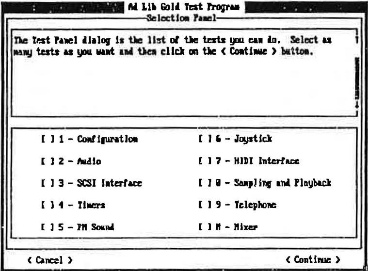
Figure 6: Test Program's Selection Panel
The options can be selected by using either the mouse, the Tab key (Tab or Tab) or the arrow keys (or ). Select the option you wish to test and then activate the <Continue> button. You can also test several options in a row by selecting the options you want and activating the <Continue> button. Any test can be executed more than once if desired.
Each test panel displays information on the test currently being performed and describes the problems and solutions which may be encountered during the test.
The Ad Lib Gold cards (models 1000 and 2000) have an on-board analog mixer that permits the volume of different audio sources to be controlled, as well as overall output volume, balance and tone. These features can be accessed using the Mixer Panel TSR.
The Mixer Panel TSR is a program that allows you to set the different sound parameters of the Ad Lib Gold card at anytime and from within any application. This memory resident program includes four different control windows:
-
Sound Parameters
-
Sub Mixer
-
Surround Features
-
Activation and Volume Keys
? TSR stands for Terminate-and-Stay Resident program, which is also called memory resident program. It is a utility program designed to remain in the computer's memory at all times after loading so the user can activate it with a keystroke at any time, even while running another program. For more information on TSRs, see Appendix D.
Loading the Mixer Panel TSR
To load the Mixer Panel TSR, set the current directory to the one where you placed the Mixer Panel at installation and type the following command:
mixer
| * NOTE: This command can be placed in a batch file so that it is loaded automatically. See your DOS user guide for details. |
When the program is loaded, it will display a message indicating that the program has been successfully loaded. It will also indicate which keys must be used to activate the Mixer Panel.
The Mixer Panel window will not open upon loading and has to be activated as explained in the next section. If you want the Mixer Panel window open upon loading the program, you can use the option " /a " with the loading command. To do this, go to the appropriate directory and type the following at the DOS prompt:
mixer /a
Activating the Mixer Panel
are the default activation keys, but you may change this combination, as explained in the "Activation and Volume Keys" section. To activate the Mixer Panel, press all of the activation keys down at the same time and release them. Upon releasing the keys, the main Mixer Panel window will appear as shown in Figure 7.
This TSR can be activated at any time with applications supporting the Ad Lib Gold. The screen will be returned to its original state and mode when you exit the Mixer Panel window.
NOTE: If you use a Hercules card with a MGA monitor, the Mixer Panel can be activated only in text mode. If you activate the Mixer Panel while in graphics mode, this may cause problems with your system.
Using the Mixer Panel
Each window of the Mixer Panel displays the different parameters and options of the Gold card (see Figure 7). To set one of these:
-
Select the item you want using the vertical arrow keys ( and ).
-
After this, you can modify the chosen item in one of the following ways:
-
increase or decrease the numerical parameters and option words one step at a time using the horizontal arrow keys ( and );
-
increase or decrease the numerical parameters ten steps at a time using Shift with the horizontal arrow keys ( and );
-
toggle On/Off parameters using the Space bar.
Sound Parameters
When the program is activated, you will see a window appear for setting the basic sound parameters of the Gold card.
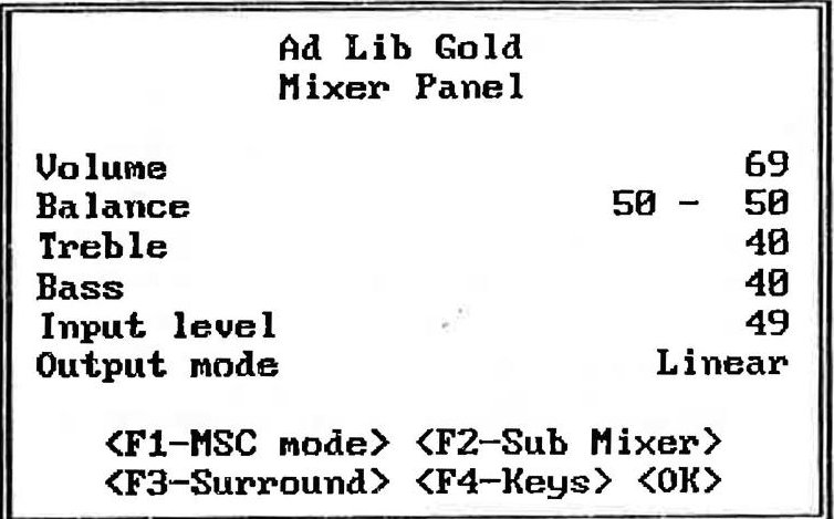
Figure 7: The main Mixer Panel window
Volume
Sets the master output volume of the board.
Balance
Sets the relative volume of the two stereo channels. Setting the right channel will automatically set the left channel; when you increase the right by one unit, the left channel decreases by one unit, and vice versa.
Treble
Sets the relative loudness of the high frequencies of the sound.
Bass
Sets the relative loudness of the low frequencies of the sound.
Input level
Sets the gain (input level) of the external auxiliary source and of the microphone.
Output mode
Sets the output mode of the audio source to one of four options:
-
Linear: without any effect on the audio source;
-
Pseudo: pseudo stereo effect that can be applied when the source is mono;
-
Mono: forced mono effect that can be applied when the source is stereo;
-
Spatial: light surround sound effect that can
be applied when the source is stereo.
The default setting is Linear.
<F1-MSC mode/Gold mode> Resets the Gold card so it is compatible with the original Ad Lib Music Synthesizer Card. This might be necessary in cases where a third party application that does not properly put the Gold card in its default mode for full compatibility with the original Ad Lib card.
<F2-Sub Mixer>
Opens the Sub Mixer window.
<F3-Surround>
Opens the Surround Features window (when using the add-on Surround Sound Module).
<F4-Keys>
Opens the ALT-SHIFT Keys (short cuts) window.
<OK> ( or Esc Closes the Mixer Panel main window and returns to the current application saving the changes you made in the settings.
Sub Mixer
Activating the F2 key when in the Mixer Panel main window will open the Sub Mixer control window. Sub Mixer parameters allow the output volume from the five different audio sources to be controlled:
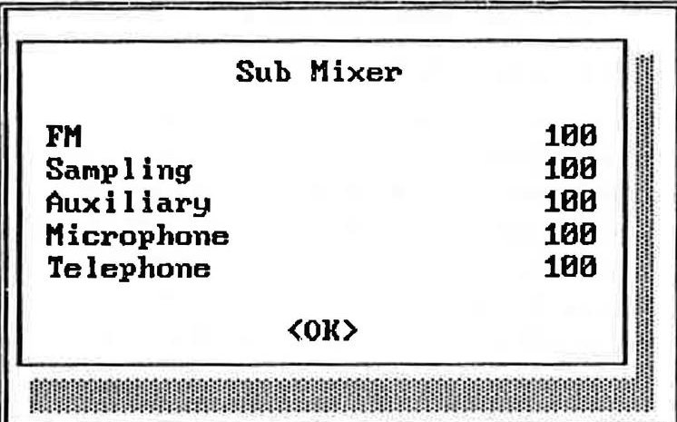
Figure 8: The Sub Mixer control window
FM
Sets the output volume of the FM source.
Sampling
Sets the output volume of the Sampling source.
Auxiliary
Sets the output volume of the auxiliary source (external or internal).
Microphone
Sets the output volume of the microphone.
Telephone
Sets the output volume of the telephone (when using the add-on Telephone Module).
<OX> ( or Esc )
Closes the Sub Mixer control window and returns to the main Mixer Panel window saving the changes you made in the Sub Mixer parameter settings.
Surround Features
Activating the key when in the Mixer Panel main window will open the Surround Features control window.
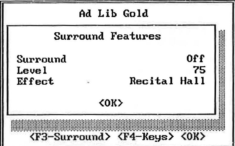
Figure 9: The Surround control window
| · | NOTE: If the Surround Sound Module is not installed, the program will display the message"OPTION NOT INSTALLED"and the changes you make to the parameters will have no effect(Fig.10). |
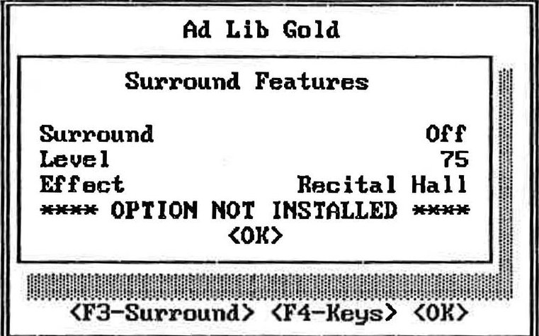
Figure 10: The Surround control window when option not installed
Surround
A toggle On/Off allows the Surround Sound option to be enabled or disabled. The default setting is Surround Off.
Level
Sets the level of the surround sound effect produced by the Surround Sound Module.
Effect
Sets the type of surround sound effect you want to enhance the sound ambience selected from a variety of presets.
<OK> ( or Esc )
Closes the Surround Features control window and returns to the main Mixer Panel window saving the changes you made in the parameter settings.
ALT-SHIFT Keys (Short Cuts)
In order to avoid conflicts with other programs, you may change the last key in the combination of keys used to activate the Mixer Panel, to set the master volume and to turn On and Off the Surround Sound. Activating the key when in the Mixer Panel main window will open the Keys window.
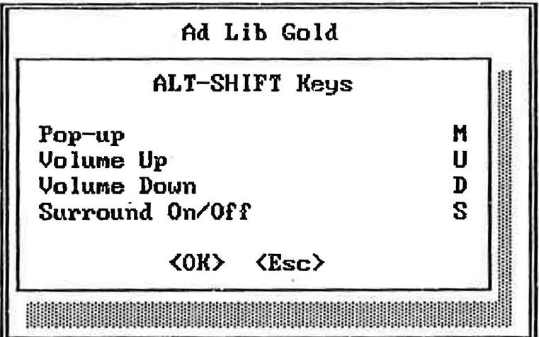
Figure 11: The ALT-SHIFT Keys window
Using the Mixer Panel
Pop-up
Sets the key combination used to activate the main Mixer Panel window. The default combination is Alt- M.
Volume Up
Sets the key combination used to increase the master volume one unit at a time. The default combination is Alt-U.
Volume Down
Sets the key combination used to decrease the master volume one unit at a time. The default combination is AIT- D.
Surround On/Off
Sets the key combination used to enable and disable the surround sound effect. The default combination is Alt- -5.
<OK> ( )
Closes the Keys window and returns to the main Mixer Panel window saving the changes you made in the control keys.
<Esc> (Esc)
Closes the Keys window and returns to the main Mixer Panel window canceling the changes you made in the control keys.
Closing the Mixer Panel
When in the main window of the Mixer Panel, press the or ESC key to leave the program and return to where you were when the Mixer Panel was activated.
Removing the Mixer Panel TSR
When the Mixer Panel TSR is already installed but you do not wish to use it, you can unload the program with the option "/x". This option removes the Mixer Panel TSR from the computer's memory. To remove the Mixer Panel TSR, go to the appropriate directory and type the following command:
mixer /r
Once this command is entered, the program will display a message indicating that the Mixer Panel has been removed.
Juke Box Gold is a music playback program specially designed to demonstrate the sound capabilities of the Ad Lib Gold card itself. It enables you to play pre-programmed songs, or those you create yourself using the Visual Composer Gold music composition program (sold separately). Selected songs can also be played at any time while other applications are running, with the use of the ROL2 Playback TSR commands.
Loading Juke Box Gold
To load Juke Box Gold, set the current directory to the one in which you placed Juke Box Gold at installation and type:
jukegold
Once the program is loaded, the main Juke Box Gold window will appear as shown in Figure 12.
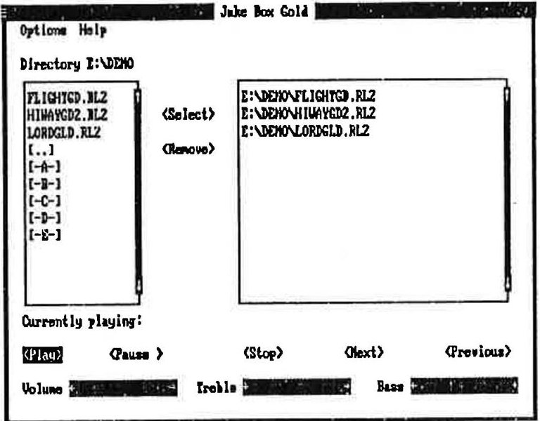
Figure 12: The main Juke Box Gold window
This window displays the various menu titles and command buttons (see Figure 12). Other possible options are contained in the menus. To activate a menu, use one of the following methods:
-
Using the Tab key: Scroll and choose the command you want with the Tab key.
-
Using the keyboard shortcuts: To activate the menu or command you want, press the Alt key and the letter highlighted in its name. To activate a command in an open menu, press the highlighted letter.
-
Using a mouse: To activate the menu or command you want, click on the menu or button command with the mouse.
Selecting Songs
Creating a Selection of Songs
The main Juke Box Gold window contains two large boxes for song selection. The box located at the left of the screen displays the contents of the current directory. This is a list of files, subdirectories and drives through which you can navigate by selecting a name and pressing the key, or by double clicking with the mouse. The name of the current directory is displayed above the box. When the program is loaded, the default directory is the directory where you placed Juke Box Gold.
To create a selection of songs, go to any directory containing ROL2 files, highlight the file and activate the Select command, or press , or double click with the mouse, for each song you wish to add to the selection. As each song is selected, its DOS file name will be displayed in the Selection box at the right of the screen in its order of selection. You may select as many songs as you wish (depending on memory capacity), but only from a single directory.
To Remove Songs from the Selection
The box at the right of the screen displays the list of songs contained in the selection you have made. To remove a song from the selection, highlight its name and activate the Remove command.
Playing Music
To Play Songs
To play your selection of songs, activate the Play command. Each song in the list will be played in order.
Once the music begins playing, the name of the song currently playing is displayed at the bottom of the window.
To Stop Music Playback
To stop music playback, activate the Stop command.
To Pause and Resume Music Playback
To pause music playback, activate the Pause command. When the music pauses, the Pause button toggles to Resume.
To continue music playback at the exact place where it stopped, activate the Resume command. Once the music starts up again, the Resume button switches back to Pause.
To Scan Songs
To skip to the next song during playback, activate the Next command. This will immediately start the next song if there are any left in the song selection list.
To return to the previous song during playback activate the Previous command. This will immediately start the previous song.
Adjusting the Sound
The Ad Lib Gold card has an on-board analog mixer that allows volume and tone controls to be adjusted. These features can be accessed from any application by using the Mixer Panel TSR program (see the section "Mixer Panel TSR"). But you can also adjust the sound directly inside the Juke Box Gold program. Three sliders located along the bottom of the window allow you to adjust volume, bass and treble controls while listening to Juke Box songs.
To Adjust the Volume, Bass or Treble
To adjust one of these three parameters, activate the slider you want and use the left and right arrow keys (and) to raise or lower the value of the chosen parameter. You can also scroll the indicator inside a slider with a mouse.
To Set the Stereo/Mono Option
The Gold card output can be set either to stereo sound (distinctive signals for the left and right channels) or mono sound (identical signals from both channels). To change from one to the other, choose the Stereo or the Mono option from the Options menu.
Asking for Help
When you choose the Help command, a window opens up on the screen containing summarized information on how to operate Juke Box Gold and how to use the various features.
Exiting the Program
To leave the program and return to DOS, use one of the following methods:
- Activate the Exit command from the Options menu.
OR
- Click on the System menu box at the upper left corner of the window and activate the Close command.
Using the ROL2 Playback TSR
The music files played by Juke Box Gold are called ROL files (.ROL or .RL2). In order to play these music files, the application uses a TSR driver, which we refer to as ROL2 Playback TSR.
Since TSRs stay in memory while we use other programs, the ROL2 Playback TSR allows you to play the songs previously selected in Juke Box Gold, while using other applications.
For details on the loading options of the ROL2 Playback TSR, see the section 4.9 "ROL2 Playback TSR".
The playback commands of this TSR can be used at any time by the following key combinations:
Alt - P Plays the selected songs.
All - - Pauses and resumes the music playback.
Alt T Stops the music playback.
All N Skips to the next song from the selection.
Returns to the previous song from the selection.
In order to avoid conflicts with other programs, you may change the last key in the combination of keys used to activate the above commands by using the Setup program.
WARNING: Do not use the ROL2 Playback TSR while running other music applications, as this will cause conflicts with the ROL2 Playback driver.
Loading Instrument Maker Gold
To load Instrument Maker Gold, type the following command at the DOS prompt:
INSGOLD
OR
ED /BBANKNAME.BNK
Where "BANKNAME" is the name of the bank.
Using Menu Commands
F5 File
New
Opens a new empty sound patch.
Open...
Opens an existing sound patch.
Close
Closes the current sound patch.
Save
Automatically saves changes made to sound patch.
Save As...
Saves the current sound patch under a new name (maximum of 11 characters).
Delete...
Deletes an existing sound patch.
Read "opl3.txt"
Save "opl3.txt"
Debug...
You do not have to use these commands. They were implemented for development and will be removed for the final version of Instrument Maker Gold.
Quit
Closes all opened sound patches, quits the Instrument Maker Gold application and returns to DOS.
F6 Options
Note Select
You do not have to use this option. It was implemented for development and will be removed for the final version of Instrument Maker Gold.
AM Depth
Amplitude Modulation Depth: When this option is checked, it increases the LFO volume modulation (tremolo).
Using Menu Commands
PM Depth
Pitch Modulation Depth: when this option is checked, it increases the LFO frequency modulation (vibrato).
Octave Up
This command makes the screen keyboard and computer keyboard play an octave higher.
Octave Down
This command makes the screen keyboard and computer keyboard play an octave lower.
F7 Document
This menu gives you a fast way to switch between open sound patch documents. It lists all the sound patch documents you have open, to a maximum of ten (including the untitled document). The checkmarked document is the active one on which you can work. An asterisk (*) placed beside a document name indicates that the document has been modified.
Editing FM Instrument Sounds
To select a parameter:
-
Click on the chosen parameter with the mouse.
-
Use the arrows to navigate between the
different parameters.
To modify a parameter:
-
Use the Space Bar to increase the value of the chosen parameter one unit at a time.
-
Use Shift- Space Bar to decrease the value of the chosen parameter one unit at a time.
-
Use the Plus Key on the numeric keyboard to increase the value of the chosen parameter one unit at a time.
-
Use the Minus Key on the numeric keyboard to decrease the value of the chosen parameter one unit at a time.
To mute operators:
- The Mute function allows you to disable (turn off) any instrument sound operator, thus making it possible to work on individual operators and listen separately to each as you change the parameters. Use the F1, F2, F3 and F4 keys to mute operators 1, 2, 3, and 4 respectively.
NOTE: In the supplied sound bank, the two-operator sound names begin with a capital letter and end with a "#", while four-operator sound names begin with a lower case letter.
Loading Sample Maker
To load Sample Maker, go to the appropriate directory and type the following command at the DOS prompt:
SAMPL
Using Menu Commands
F5 File
New
Opens a new empty sampled sound.
Open from Bank...
Opens an existing sampled sound in ADPCM format from the bank.
Save to Bank As...
Saves the current sampled sound in ADPCM format under a new name in the bank.
Delete from Bank...
Deletes an existing sampled sound in ADPCM format from the bank.
WARNING: All sampled sounds saved to bank are temporarily limited to 64 K. Furthermore, the format of sampled sounds saved to bank will change in the next development versions. For these reasons, we recommend that you do not use the commands related to a bank.
Compact Bank
You do not have to use this command. It was implemented for development and will be removed for the final version of Sample Maker.
Open File...
Opens an existing sampled sound in PCM format (.SMP file) from the current directory.
Save File As...
Saves the current sampled sound in PCM format (as .SMP file) in the current directory.
Open Sample Vision File...
Open Lyre File...
You do not have to use these commands. They were implemented for development and will be removed for the final version of Sample Maker.
Quit
Closes the displayed sampled sound, quits the Sample Maker application and returns to DOS.
F6 Edit
Copy
Copies the selected section of the sampled sound and puts it into a memory buffer.
| Using Menu Commands | |
| Cut Deletes the selected section from the sampled sound and puts it into a memory buffer. | Sampling Params... Use this command to determine the value of the various parameters related to the sampled sound you are working on. |
| Paste Inserts a copy of the buffer's contents at the point where the cursor is positioned in the displayed sampled sound. | |
| Clear Deletes the selected section from the sampled sound, but, unlike the command Cut, does not put it into the buffer. | F8 Options Scope Mode This command makes Sample Maker's screen display the sampled signal received at the input as a scope. |
| Clear All Deletes the entire sampled sound from the screen. | NOTE: When in Scope Mode, only the sampling frequency (in PCM) is an effective parameter in the "Sampling Params..." dialog. |
| F7 Sampling Record This command enables any audio signals mixed with the Gold card to be recorded and sampled with Sample Maker. The sampling process will follow the sampling parameters defined within the Sampling Params... dialog. | Scale Up Each time you use this command, Sample Maker zooms the displayed sampled sound out horizontally by a ratio of 1 to 1/2. |
| Play This command lets you listen to the opened sample sound. When a section of the sampled sound is selected, you will only hear that section played. | Scale Down Each time you use this command, Sample Maker zooms the displayed sampled sound in horizontally by a ratio of 1 to 2. |
| Scale Reset Resets a zoomed out sampled sound to the original 1 to 1 scale. | |
ADPCM File Format
This command is grayed out because you do not have to use it. The PCM to ADPCM file format converter is not completely implemented at this time.
Gen. Example
This command automatically generates a sampled sin wave and pastes it onto the screen. You should not use this command. It was implemented for development and will be removed for the final version of Sample Maker.
Important Warnings for this Development Version of Sample Maker
Sampling Rate Limitations
-
Due to a limitation of the sampling chip, the sampling rate of 5.5125 kHz does not work in 4-bit PCM format. Do not choose this option because Sample Maker will then set another sampling rate, which will give unexpected results.
-
Due to a limitation of the sampling chip, the sampling rate of 44.1 kHz does not work in 4bit ADPCM format. Do not choose this option because Sample Maker will then set another sampling rate, which will give unexpected results.
See "Digital Input and Output".
Sampling Length Limitation
- Sampled sounds are limited to 256 K. If a recording goes over 256 K, it will clip at 256 K.
Scope Mode
- When in Scope Mode, choosing the Record command will make the program lock up.
Graphic Display In Different PCM Format
- Even though every PCM format makes Sample Maker record and play correctly, only PCM 8-bit format is displayed correctly on screen.
Ad Lib Surround Sound Editor
Ad Lib is providing a special application program, the Surround Sound Editor, which allows you to program your own presets for the Surround Sound Module. This program is included within a special version of Juke Box Gold so that you may play back Juke Box songs and listen to changes you make while working in the editor.
Technical Features
The underlying technology of the Surround Sound Module is a circuit designed as a general-purpose digital processing element. The board's main component is an LSI chip which has quality digital surround sound capabilities made possible through Yamaha's digital audio technology. Each of its eight digital delay lines may provide a delay time of up to 100 milliseconds, and combining delay line signals for two-channel output assures a wide range of applications.
Opening the Surround Sound Editor
As stated above, the Surround Sound Editor is at this moment included within a special version of Juke Box Gold. So, to open the editor, you first have to load Juke Box Gold.
To load Juke Box Gold with the Surround Sound Editor, set the current directory to the one in which you placed Juke Box Gold during installation and type the following command:
surround
Once the program is loaded, the main Juke Box Gold window will appear. You can then select and play back songs as you wish. For complete information on using Juke Box Gold, refer to the "Juke Box Gold Music Playback Program" section of Ad Lib Gold Pre-Release Evaluation Kit.
When ready, open the Surround Sound Editor by choosing Surround from the Options menu. Upon opening, the Surround Sound Editor window will appear as shown in the following figure.
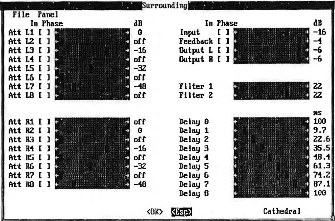
The Surround Sound Editor window
This window displays the various parameters used to construct a surround sound effect.
Using the Surround Sound Editor
The Surround Sound Editor window contains five main parts:
- The left channel line attenuation section, located
at the upper left corner of the screen.
-
The right channel line attenuation section, located at the lower left corner of the screen.
-
The global level and feedback parameter section, located at the upper right corner of the screen.
-
The filter parameter section, located in the middle of the right side of the screen.
-
The global delay line parameter section, located at the lower right corner of the screen.
Channel Line Attenuation Sections
These two sections display the two delay line attenuation parameters related to left and right channels.
In Phase
When this check box is checked off, means that the delay line output signal is in phase with the input signal. When this check box is not checked off, means that the delay line output signal is phase reversed with the input signal.
dB
Displays the attenuation value setting of the delay line, which ranges from -60 decibels to 0 decibels, in steps of 2 dB. A delay line can also be turned off (-oo).
Global Level and Feedback Parameter Section
This section displays the two global attenuation parameters related to global signal input, feedback output, and left and right channel global outputs.
In Phase
When this check box is checked off, means
that the output signal is in phase with the input signal. When this check box is not checked off, means that the output signal is phase reversed with the input signal.
dB
Displays the attenuation value setting of the signal, which ranges from -60 decibels to 0 decibels, in steps of 2 dB. A signal can also be turned off (- ∞).
Filter Parameter Section
This section displays the value setting of the two low pass filters for the feedback loop, which ranges from 0 to 31 units, in steps of 1 unit.
Global Delay Line Parameter Section
ms
Displays the time value setting for each of the 8 delay lines (Delay 1 to Delay 8) and the feedback loop delay line (Delay 0), which range from 0 to 100 milliseconds, in steps of approximately 3.2 milliseconds.
Editing Surround Sound Presets
To modify a parameter, use one of the following methods:
-
Click on the slide bar indicator of the chosen parameter with the mouse and drag it to the desired value.
-
Click on the gray zone of a slide bar to move the indicator and to decrease or increase the value of the chosen parameter several steps at a time.
-
Click on the left or right arrows at the end of a slide bar to decrease or increase the value of the chosen parameter one step at a time.
-
Click on a check box to turn it On or Off.
Using Menu Commands
To activate menu commands, use one of the following methods:
-
Using a mouse: To activate a menu command, click on the menu with the mouse, drag to the command you want and release the mouse button.
-
Using the keyboard shortcuts: To activate a menu command, press the letter highlighted in the menu's name and the Alt key at the same
time. Then, activate the command you want by pressing the letter highlighted in its name.
File Menu
New
Opens a new empty surround sound preset with no name.
Open
Opens an existing surround sound preset from the bank entitled STANDARD .SRD.
Save
Opens a dialog box which allows the current surround sound preset to be saved under a chosen name (maximum of 8 characters) in the bank entitled STANDARD .SRD.
Text
This command will save the current preset in text form, in both C and Assembler formats, in the file PRESET.TXT. If PRESET.TXT exists, the text will be appended
Delete
Deletes an existing surround sound preset from the bank entitled STANDARD . SRD.
Panel Menu
Opens an existing surround sound preset from the Control Panel executable file (CONTROL.EXE).
Saves the current surround sound preset in the Control Panel executable file (CONTROL.EXE).
NOTE: This command does not allow the name of the current surround sound preset to be changed.
Closing the Surround Sound Editor
Closes the Surround Sound Editor window and returns to Juke Box Gold, temporarily keeping the changes you have just made to the current preset for a further work session.
Closes the Surround Sound Editor window and returns to Juke Box Gold, without keeping the changes you have just made to the current preset.
ROL2 Playback Utility
The ROL2 Playback utility is a small program that allows the user to play RL2 music files from the DOS command line or from a batch file.
The format of the command running the ROL2 Playback utility is the following:
playrl2 fileName [/Q]
Where fileName is the name of the ROL2 music file (.RL2) to be played.
The optional "/Q" parameter can be used to start the playback of the RL2 song file and immediately returns control to DOS. The playback of the song will be taken in charge by the ROL2 Playback memory resident driver.
If you enter "playrl2" alone or with the option "/?" ("playrl2 /?"), the program displays help lines giving summarized information on program parameters.
The ROL2 Playback utility uses the following five drivers, which have to be loaded before running it:
-
Control driver (CTRLDRV.EXE)
-
FM driver (FMDRV.EXE)
-
Timer driver (TIMERDRV.EXE)
-
Wave driver WAVEDRV.EXE)
-
ROL2 Playback driver (RL2DRV.EXE)
Digitized Sound Playback Utility
The Digitized Sound Playback utility is a small program that allows to play back digitized sound files (recorded in the .SMP format) from the DOS command line or from a batch file.
The format of the command running the Digitized Sound Playback utility is the following:
playdigi fileName [/p] [/n]
Where fileName is the name of the digitized sound file (.SMP) to be played.
Where "p" in the option "/p", may be "C" (center), "R" (right), or "L" (left), indicating the stereo position you want for the playback of the digitized sound file.
Where "n" in the option "/n", may be a number from 0 to 100, indicating the volume you want for the playback of the digitized sound file.
If you enter "playdigi" alone or with the option "/?" ("playdigi /?"), the program displays help lines giving summarized information on program parameters.
The Digitized Sound Playback utility uses the following two drivers, which have to be loaded before running it:
-
Control driver (CTRLDRV.EXE)
-
Wave driver (WAVEDRV.EXE)
Using the ROL2 Playback TSR
The music files played by Juke Box Gold are called ROL files (.ROL or .RL2). In order to play these music files, the application uses a TSR driver, which we refer to as ROL2 Playback TSR.
The ROL2 Playback TSR is used by various applications to control the playback of Ad Lib music files. It is a powerful utility that uses the services of the other underlying drivers to simplify the task of integrating music and digitized sound to applications. (See below for the options supported with this driver.)
Since TSRs stay in memory while we use other programs, the ROL2 Playback TSR allows you to play the songs previously selected in Juke Box Gold, while using other applications.
The playback commands of the ROL2 Playback TSR can be used at any time by the following key combinations:
Alt P Plays the selected songs.
Alt- A Pauses and resumes the music playback.
Alt - T Stops the music playback.
Alt N Skips to the next song from the selection.
Returns to the previous song from the selection.
In order to avoid conflicts with other programs, you may change the last key in the combination of keys used to activate the above commands by using the Setup program.
! WARNING: Do not use the ROL2 Playback TSR while running other music applications, as this will cause conflicts with the ROL2 Playback driver.
ROL2 Playback TSR Data Files
The ROL2 Playback TSR uses the a number of data files. All the data files must be in the same directory. Unless the path for these files is specified as a command line argument, the directory containing those files must be the current directory when RL2DRV.EXE is loaded. The data files used by the ROL2 Playback TSR are:
-
SAMPLES.BNK and OPL3.BNK: instrument description files (for digitized and FM sounds, respectively).
-
SAMPLBNK.EQU: Digitized sounds name translation table.
-
*.SMP: Digitized sound files used in the songs.
ROL2 Playback TSR Options
The following command-line options can be used with the ROL2 Playback TSR:
r12drv /r
This option removes the ROL2 Playback TSR from the computer's memory when it is installed but you do not wish to use it. Once this command is entered, the program will display a message indicating that the ROL2 Playback TSR has been removed and is no longer loaded.
r12drv
Loads the ROL2 Playback TSR into the computer's memory (RAM).
r12drv /vn
This option disables the specified sampling voice "n", which can be "1" or "2". Use two options consecutively, "/v1 /v2", to disable the two sampling voices.
The playback of sampled voices consumes a lot of computer resources. On slower PCs, or when the ROL2 Playback TSR is used in conjunction with more demanding applications, this option can be used to ensure a proper functioning of all parts involved.
r12drv /spath
This option is used to specify a path for the data files used by ROL2 Playback TSR, if the data files are not in the default directory.
Chapter 5 - DOS Software Drivers
The DOS Control Features, FM (OPL3), Wave, Timer and MIDI drivers, and their complete function references.
This batch file command loads all Ad Lib Gold drivers.
Introduction iii
5.1 Interfacing DOS Drivers with Applications 1
5.2 DOS Control Features Driver 3
Function Directory 4
5.3 DOS FM Synthesis Driver 57
Voice Allocation Structure 57
Function Directory 58
5.4 DOS Wave Driver 71
DOS Wave Driver Functions 71
5.5 DOS Timer Driver 93
Function Directory 95
5.6 DOS MIDI Driver
(To be released)
5.7 DOS SCSI CD-ROM Driver
(To be released)
Ad Lib supplies memory-resident drivers as part of its end-user software packages. Developers should, when possible, use the services provided by those drivers. There are a number of advantages to using memory-resident drivers:
-
A lot of the applications supplied for the Gold Card are TSR applications. Memory-resident drivers provide applications with a common software core for managing shared resources. Digital playback and recording, MIDI input and output and the timers available on the card, for instance, share a same interrupt request line.
-
Memory-resident drivers can easily be maintained and updated, independently of the application code.
The method used by applications to interface with the Ad Lib Gold memory-resident drivers minimizes the overhead in calling the driver services. For most applications, calling the drivers services will not introduce a noticeable overhead.
The following drivers are available as part of the developer toolkit.
DOS Control Features Driver
The DOS Control Features driver supports the mixer features defined in Gold Sound Standard architecture
It also controls the configuration options of the Gold card, such as interrupt line selection, DMA channel allocation and address relocation.
Finally, it acts as a main management layer for all other drivers. It manages interrupt redirection to other drivers and keeps track of the location of the drivers.
For this reason, the Control features driver should always be the first one loaded.
DOS FM Driver
The DOS FM driver gives access to the FM sound generation features of the YMF262 chip.
DOS Wave Driver
The DOS Wave Driver supports the digitized sound playback and recording features of the YMZ263 chip.
DOS Timer Driver
The DOS Timer driver supplies routines to control the hardware timers on both the YMF262 and the YMZ263 chips. The timers can be used for high-precision synchronization of events.
DOS MIDI Driver
The DOS MIDI driver offers services to input and output data through the YMZ263 MIDI FIFO buffers.
Drivers load themselves in memory and hook themselves to the DOS multiplex interrupt 2FH. Once a driver is loaded in memory, it registers itself to the Control features driver. It transmits to the Control features driver the address for an entry point to be used by applications, and an address for an entry point to a routine that will handle interrupts from the Gold card.
There are two ways an application can interface with a driver. By issuing commands through int 2FH, or by directly calling the driver entry-point function, used for command dispatching. The second method is much more efficient.
To directly call the driver entry-point function, an application that wants to use the services of a driver first needs to issue an interrupt 2FH with register AH equal to ADLIB_MULTIPLEX_DRIVER_ID and register AL equal to the GET_ALL_ENTRY command (defined in ctrldrv.h). This will return a table containing the entry points for all Gold drivers present in memory.
The application can then communicate with a specific driver just by issuing a FAR call to a specific driver. This call will take as an argument a far pointer to an argument-passing structure which is specific to each driver.
The Developer Toolkit supplies a set of linkable modules that are used to ease the interfacing to the drivers, using the second method of interfacing. The Link modules hide all the complexity of interfacing to the drivers. The application just needs to call the drivers functions as if they were part of a linkable library.
The modules can use the second method of communicating with the drivers. In order to do this, they have to call an initialization function, InitxxxLink(). These functions will build up a table of function pointer to accelerate the calling of driver routines.
| Driver link module | Description | Link Initialization routine |
| CTRLLNK | Control Features Driver | InitCtrlLink() |
| FMLNK | FM Synthesis Driver | InitFMLink() |
| WAVELNK | Wave Driver | InitWaveLink() |
| TIMERLNK | Timer Driver | InitTimerLink() |
| MIDILNK | MIDI Driver | InitMidiLink() |
Once the InitxxxLink() function is called, applications just need to call the routines described in the following sections.
The source code for the Link modules has been supplied as part of the Developer Toolkit. Developers can use this source to customize Link modules to their version of the C compiler. The source code can also be used as a reference in debugging environments.
Initialization Sequence
Developers using the Gold drivers should use the following initialization steps in order to insure that their applications do not try to access drivers that are not loaded in memory.
Applications should first check for the presence of the Gold card. They should then make sure that the driver is present by calling the appropriate function.
Once the application has made verified that the driver is loaded in memory, it can call the appropriate InitxxxLink() function.
| Driver or service | Detection function | Returns |
| Gold Card Presence | CtGetGoldCardPresence() | 0 if the Gold card is not found.1 If the Gold card is found |
| Control Features Driver | CtGetDriverPresence() | 0 if the driver is not present.1 if the driver is loaded |
| FM Synthesis Driver | GetFMDriverStatus() | 0xFF if the driver is present |
| WAVELNK | GetWaveDriverStatus() | 0xFF if the driver is present |
| TIMERLNK | GetTimerDriverStatus() | 0xFF if the driver is present |
| MIDILNK | GetMIDIDriverStatus() | 0xFF if the driver is present |
SetControlRegister
Syntax
int SetControlRegister(int reg, WORD val) Sets register 'reg' of Ad Lib Control Chip to 'val'.;
Parameters
int reg Which register to write to. WORD val Which value to write in register.
Return value
If no error 0, otherwise 1.
Comments
This low-level routine handles the details related to accessing the Control Chip, like interrupt disabling and reenabling. It also verifies that no access is made while the Control Chip's RB & SB bits are set.
CtStoreConfigInPermMem
Syntax
WORD CtStoreConfigInPermMem();
This causes all control chip registers, in their current state, to be written to permanent memory.
Parameters
None
Return value
1 if ok. 0 if a problem occured.
Comments
None
CtRestoreConfigFromPermMem
Syntax
WORD CtRestoreConfigFromPermMem() Restores the Gold crd configuration from permanent memory.;
CtSetChannel0SampGain
CtSetChannel1SampGain
CtGetChannel0SampGain
CtGetChannel1SampGain
Syntax
WORD CtSetChannel0SampGain(WORD value);
WORD CtSetChannel1SampGain(WORD value);
WORD CtGetChannel0SampGain(WORD value);
WORD CtGetChannel1SampGain(WORD value);
Sets the gain of sampling channels.
Parameters
WORD value
Gain value from 0 to 255.
256 different values possible giving a range from approximately 0.04 to 10 times the input value. The exact gain is given by the equation:
Gain = (registerValue * 10) / 256 Linear gain.
Return value
1 if ok.
Comments
None
CtSetChannelFilter0Mode
CtSetChannel1FilterMode
Syntax
WORD CtSetChannel0FilterMode(WORD value);
WORD CtSetChannel1FilterMode(WORD value);
Sets the antialiasing fiters in the proper mode for the channel.
Parameters
WORD value
0 = playback mode, 1 = sample mode
Return Value
1 if ok.
Comments
This filter MUST be set in sample mode before sampling.
This filter MUST be set in playback mode before playback.
The Ad Lib Gold card uses the same antialiasing filters during sampling and playback. The appropriate filter mode must be set before any sampling or playback operation.
CtGetChannelFilter0Mode
CtGetChannel1FilterMode
Syntax
WORD CtGetChannel0FilterMode(void);
WORD CtGetChannel1FilterMode(void);
Returns the current antialisaing filter mode for the channel.
Parameters
None
Return Value
0: playback mode. 1: Sampling mode
Comments
None
CtStereoMonoAuxSamp
Syntax
WORD CtStereoMonoAuxSamp(WORD value);
Forces auxiliary inputs to work monophonically or sterophonically.
Parameters
WORD value
0 = auxiliary input is stereo, 1 = auxiliary input is mono
Return Value
1 if ok.
Comments
The microphone and telephone inputs are monophonic sources and can only be sampled monophonically on channel 0. However, the auxiliary inputs are normally sampled in stereo on both channel 0 and 1 at the same time. This stereo audio input can be turned monophonic and sampled on channel 0 using this function.
CtGetStereoMonoAuxSamp
Syntax
WORD CtGetStereoMonoAuxSamp(void);
Returns whether the auxiliary inputs are used for monophonic sampling or stereophonic sampling.
Parameters
None
Return Value
0 = auxiliary input is stereo, 1 = auxiliary input is mono
Comments
None
CtEnabDisabMicroOutput
Syntax
WORD CtEnabDisabMicroOutput(WORD value);
Enables/disables microphone output.
Parameters
WORD value
0 = Microphone output enabled, 1 = Microphone output disabled
Return Value
1 if ok.
Comments
When using the microphone input and the normal loudspeaker outputs of the audio card, audio feedback could result. In normal mode, microphone output is enabledd When disabled, the microphone signal is cut from the output of the card but sent to the telephone output, eliminating possible causes of feedback.
CtGetEnabDisabMicroOutput
Syntax
WORD CtGetEnabDisabMicroOutput();
When using the microphone input and the normal loudspeaker outputs of the audio card, audio feedback could result. In normal mode, this bit is set to 0. When set to 1, the microphone signal is cut from the output of the card and only sent to the telephone output, eliminating possible causes of feedback.
Parameters
None
Return Value
0 = Microphone output enabled, 1 = Microphone output disabled Comments
See CtEnabDisabMicroOutput()
CtEnabDisabInternPcSpeak
Syntax
WORD CtEnabDisabInternPcSpeak(WORD value);
Enables/Disables redirection of the PC internal speaker output to to the Gold mixer.output
Parameters
WORD value
0 = Disconnect internal PC speaker,
1 = Connect internal PC speaker
Return Value
1 if ok.
Comments
This can enable the PC internal speaker signal to be mixed with the audio signals of a Gold card (directly, without any mixer volume control).
CtGetEnabDisabInternPcSpeaker
Syntax
WORD CtGetEnabDisabInternPcSpeaker();
Returns the state of redirection of the PC speaker.
Parameters
None
Return Value
0 = Internal PC speaker not redirected.
1 = Internal PC speaker redirected
Comments
None
CtSelectInterruptLineNbr
Syntax
WORD CtSelectInterruptLineNbr(WORD value);
Selects the interrupt request line used by the audio portion of the Gold hardware.
Parameters
WORD value
0 = IRQ3, 1 = IRQ4, 2 = IRQ5, 3 = IRQ7
4 = IRQ10, 5 = IRQ11, 6 = IRQ12, 7 = IRQ15
Return Value
1 if ok.
Comments
The interrupt line is used by OPL3, MMA and telephone hardware. Valid interrupt lines on an XT are IRQ3, IRQ4, IRQ5 and IRQ7. Valid interrupt lines on an AT are IRQ3, IRQ4, IRQ5, IRQ7, IRQ10, IRQ11, IRQ12 and IRQ15.
CtGetInterruptLineNbr
Syntax
WORD CtGetInterruptLineNbr();
Returns a number indicating the interrupt line used by the audio portion of the Gold hardware..
Parameters
None
Return Value
0 = IRQ3, 1 = IRQ4, 2 = IRQ5, 3 = IRQ7
4 = IRQ10, 5 = IRQ11, 6 = IRQ12, 7 = IRQ15
Comments
None
CtSelectDMA0ChannelSampChan
CtSelectDMA1ChannelSampChan
Syntax
WORD CtSelectDMA0ChannelSampChan(WORD value);
WORD CtSelectDMA1ChannelSampChan(WORD value);
Allocates DMA channel for the specified MMA sampling channel.
Parameters
| WORD | value |
| 0=DMA0 | |
| 1=DMA1 | |
| 2=DMA2 | |
| 3=DMA3 |
Return Value 1 if ok.
Comments
Only DMA channels 1,2 and 3 are available on model Gold 1000. All listed DMA channels are available on the Gold 2000 and 2000MC.
CtGetDMA0ChannelSampChan
CtGetDMA1ChannelSampChan
Syntax
WORD CtGetDMA0ChannelSampChan();
WORD CtGetDMA1ChannelSampChan();
Returns a number indicating the DMA channel used by the specified sampling channel.
Parameters
None
Return Value
The sampling channel used.
Comments
None
CtEnabDisabDMA0SampChan
CtEnabDisabDMA1SampChan
Syntax
WORD CtEnabDisabDMA0SampChan(WORD value);
WORD CtEnabDisabDMA1SampChan(WORD value);
Disables or enables use of DMA channel for sampling channel.
Parameters WORD value 0 = disable, 1 = enable
Return Value 1 if ok.
Comments None
CtGetEnabDisabDMA0SampChan
CtGetEnabDisabDMA1SampChan
Syntax
WORD CtGetEnabDisabDMA0SampChan();
WORD CtGetEnabDisabDMA1SampChan();
Tells if the DMA channel is disabled or enabled for the specified sampling channel.
Parameters
None
Return Value
0 = disabled, 1 = enabled
Comments
None
CtSetRelocationAddress
Syntax
WORD CtSetRelocationAddress(value);
Set s the base ports address for MMA, OPL3 and control chip.
Parameters
WORD value
New I/O address, divided by 8.
Return Value 1 if ok.
Comments
None
CtGetRelocationAddress
Syntax
WORD CtGetRelocationAddress();
Returns the base port addresses for MMA, OPL3 and control chip.
Parameters
None
Return Value
New base I/O address, divided by 8.
Range is from 0 to 127
Comments
None
CtSetMixerLevelForFMLeft
CtSetMixerLevelForFMRight CtSetMixerLevelForLeftSamplePb CtSetMixerLevelForRightSamplePb CtSetMixerLevelForAuxLeft CtSetMixerLevelForAuxRight CtSetMixerLevelForMicrophone CtSetMixerLevelForTelephone
Syntax
WORD CtSetMixerLevelForFMLeft(WORD value);
WORD CtSetMixerLevelForFMRight(WORD value);
WORD CtSetMixerLevelForLeftSamplePb(WORD value);
WORD CtSetMixerLevelForRightSamplePb(WORD value);
WORD CtSetMixerLevelForAuxLeft(WORD value);
WORD CtSetMixerLevelForAuxRight(WORD value);
WORD CtSetMixerLevelForMicrophone(WORD value);
WORD CtSetMixerLevelForTelephone(WORD value);
Sets the volume for the specified device
Parameters
WORD value
Volume level from 128 to 255 whereas 128 is the minimum, 255 the maximum.
Return Value
1 if ok.
Comments
Writing a value less than 128 will result in a signal with negative polarity and should be avoided because the resulting signal may cancel out another signal of opposite polarity.
CtGetMixerLevelForFMLeft
CtGetMixerLevelForFMRight
CtGetMixerLevelForLeftSamplePb
CtGetMixerLevelForRightSamplePb
CtGetMixerLevelForAuxLeft
CtGetMixerLevelForAuxRight
CtGetMixerLevelForMicrophone
CtGetMixerLevelForTelephone
Syntax
WORD CtGetMixerLevelForFMLeft();
WORD CtGetMixerLevelForFMRight();
WORD CtGetMixerLevelForLeftSamplePb();
WORD CtGetMixerLevelForRightSamplePb();
WORD CtGetMixerLevelForAuxLeft();
WORD CtGetMixerLevelForAuxRight();
WORD CtGetMixerLevelForMicrophone();
WORD CtGetMixerLevelForTelephone();
Returns the volume of the specified device.
Parameters
None
Return Value
Volume level from 128 to 255 whereis 128 is the minimum, 255 the maximum.
Comments
None
CtSetOutputVolumeLeft
CtSetOutputVolumeRight
Syntax
WORD CtSetOutputVolumeLeft(WORD value);
WORD CtSetOutputVolumeRight(WORD value);
Sets the final output volume
Parameters
WORD value Volume level from 0 to 255
Return Value 1 if ok.
Comments
There are actually 64 final volume levels. The driver divides the specified value by 4.
CtGetOutputVolumeLeft
CtGetOutputVolumeRight
Syntax
WORD CtGetOutputVolumeLeft();
WORD CtGetOutputVolumeRight();
Returns the the final output volume
Parameters
None
Return Value
Final output volumefrom 0 to 255
Comments
There are actually 64 final volume levels. The driver multiplies the specified value by 4 in the return value.the return value may not correspond exactly to the value specified with CTSetOutputVolumeXXX().
CtSetOutputBassLevel
CtSetOutputTrebleLevel
Syntax
WORD CtSetOutputBassLevel(WORD value);
WORD CtSetOutputTrebleLevel(WORD value);
Sets the output bass and treble level.
Parameters
WORD value Range from -128 to 127.
Return Value 1 if ok.
Comments
Negative values decreases trebleor bass, positive numbers, increase treble or bass. 0 does not alter sound.
CtGetOutputBassLevel
CtGetOutputTrebleLevel
Syntax
WORD CtGetOutputBassLevel();
WORD CtGetOutputTrebleLevel();
Returns the bass or treble level setting.
Parameters
None
Return Value
Bass or treble setting, from -127 to 127
Comments
Since only 4 bits are actually used in the control Chip, the result obtained can differ with the value written using the CtSetOutputBassLevel() and CtSetOutputTrebleLevel function, due to rounding errors.
CtEnabDisabOutputMuting
Syntax
WORD CtEnabDisabOutputMuting(value) Disables or enables output muting.;
Parameters WORD value 0 = disable, 1 = enable
Return Value 1 if ok.
Comments None
CtGetEnabDisabOutputMuting
Syntax
WORD CtGetEnabDisabOutputMuting();
Returns a value indicating if output muting is disabled or enabled.
Parameters
None
Return Value
0: disabled, 1: enabled
Comments
None
CtSelectSCS1InterruptNumber
Syntax
WORD CtSelectSCSIInterruptNumber(WORD value);
Selects an interrupt request line for the SCSI hardware on the Goldcard.
Parameters
| WORD | value |
| 0=IRQ3 | |
| 1=IRQ4 | |
| 2=IRQ5 | |
| 3=IRQ7 | |
| 4=IRQ10 | |
| 5=IRQ11 | |
| 6=IRQ12 | |
| 7=IRQ15 |
Return Value
1 if ok.
Comments
Valid interrupt lines on an XT are IRQ3, IRQ4, IRQ5 and, IRQ7. Valid interrupt lines on an AT are IRQ3, IRQ4, IRQ5, IRQ7, IRQ10, IRQ11, IRQ12 and IRQ15.
CtGetSCSIInterruptNumber
Syntax
WORD CtGetSCSIInterruptNumber();
Returns a number indicating the interrupt request line used by the SCSI hardware on the Gold card.
Parameters
None
Return Value
Interrupt request line:
Comments
None
CtEnabDisabSCSIIinterrupt
Syntax
WORD CtEnabDisabSCSIIinterrupt(value) Disables or enables interrupt from SCSII.;
Parameters WORD value 0 = disable, 1 = enable
Return Value 1 if ok.
Comments None
CtEnabDisabSCSIDMA
Syntax
WORD CtEnabDisabSCSIDMA(value) Disables or enables DMA transfers on SCSI hardware.;
Parameters
WORD
0 = disable, 1 = enable
Return Value 1 if ok.
Comments None
CtGetEnabDisabSCSIInterrupt
Syntax
WORD CtGetEnabDisabSCSIInterrupt();
Returns 1 if interrupts are enabled on the SCSI hardware.
Parameters
None
Return Value
0: Interrupts are disabled
1: Interrupts are enabled
Comments
None
CtGetEnabDisabSCSIDMA
Syntax
WORD CtGetEnabDisabSCSIDMA();
Returns 1 if DMA transfers are enabled on the SCSI hardware.
Parameters
None
Return Value
0: DMA is disabled
1: DMA is enabled
Comments
None
CtSelectSCSIDMAChannel
Syntax
WORD CtSelectSCSIDMAChannel(WORD value);
Assigns a DMA channel to the SCSI hardware of the Gold Card.
Parameters
| WORD | value |
| 0=DMA0 | |
| 1=DMA1 | |
| 2=DMA2 | |
| 3=DMA3 |
Return Value
1 if ok.
Comments
Valid DMA channels are 0-3. Other channel numbers are reserved for future extensions.
CtGetSCSIDMAChannel
Syntax
WORD CtGetSCSIDMAChannel();
Returns the number of the DMA channel Assigned to the SCSI hardware of the Gold card.
Parameters
None
Return Value
Comments
None
CtSetSCSIRelocationAddress
Syntax
WORD CtSetSCSIRelocationAddress(value);
Sets the base port address addresses for SCSI controller.
Parameters
WORD value
New base I/O address divided by 8.
Range from 0 to 127.
Return Value
1 if ok.
Comments
None
CtGetSCSIRelocationAddress
Syntax
WORD CtGetSCSIRelocationAddress();
Returns the base port address for SCSI controller.
Parameters
None
Return Value
New base I/O address divided by 8. Range from 0 to 127.
Comments
None
CtSetHangUpPickUpTelephoneLine
Syntax
WORD CtSetHangUpPickUpTelephoneLine(WORD value) Hangs up or picks up telephone.;
Parameters
WORD value
0 = Disconnect telephone line,
1 = Connect telephone line
Return Value
1 if ok.
Comments
None
CtGetHangUpPickUpTelephoneLine
Syntax
WORD CtGetHangUpPickUpTelephoneLine();
Returns a value telling if the telephone line is on-hook or off-hook.
Parameters
None
Return Value
0: telephone line is on-hook (not connected)
1: telephone line is off-hook (connected)
Comments
None
CtSelectOutputSources
Syntax
WORD CtSelectOutputSources(value);
Selects final output mixing redirection.
Parameters
0 = left mixer channel to left output & right mixer channel to right output,
1 = left mixer channel to both left and right outputs,
2 = right mixer channel to both left and right outputs.
Return Value
1 if ok.
Comments
On the Adlib Gold cards, mixing and volume control is performed in two stages. First, all sources are sent to a stereo mixer. Then, the stereo output of the mixer is fed into the final volume control circuitry. The final left and right outputs can be mixed in the fashion described above.
CtGetOutputSources
Syntax
WORD CtGetOutputSources();
Returns the final mixer redirection mode.
Parameters
None
Return Value
0 = left mixer channel to left output & right mixer channel to right output,
1 = left mixer channel to both left and right outputs,
2 = right mixer channel to both left and right outputs.
Comments
None
CtSelectOutputMode
Syntax
WORD CtSelectOutputMode(value);
Controls the effect applied to the final output.
Parameters
WORD value
0 = Forced mono,
1 = linear stereo,
2 = pseudo stereo,
3 = spatial stereo.
Return value
1 if ok.
Comments
Linear stereo is ordinary, with no effects added. The spatial and pseudo-stereo effects will be useful primarily when the original source is monophonic.
CtGetOutputMode
Syntax
WORD
CtGetOutputMode()
Returns the effect applied to the final output .
Parameters
None
Return value
0 = Forced mono,
1 = linear stereo,
2 = pseudo stereo,
3 = spatial stereo.
Comments
None
GetControlRegister
Syntax
WORD GetControlRegister(reg) Returns value stored on register 'reg' of Ad Lib Control Chip.;
Parameters int reg Which register to read from.
Return value Returns the WORD at the register position.
Comments None
CtGetBoardIdentificationCode
Syntax
WORD CtGetBoardIdentificationCode() Returns the board identification code.;
Parameters
None
Return value
Board identification code:
0- Gold 2000,
1- Gold 1000,
2- Gold 2000 MC.
Comments
None
CtGetBoardOptions
Syntax
WORD CtGetBoardOptions();
Returns a bit pattern indicating the options present on boardpresent
Parameters
None
Return value
Bit 0-3 (0 = not present, 1 = installed)
bit 0 - Telephone,
bit 1 - Surround,
bit 2 - SCSI,
bit 3 - Currently unused
Comments
None
CtGetControllerStatus
Syntax
WORD CtGetControllerStatus();
Returns the interrupt controller status.
Parameters
None
Return value
bit 0 - equals 1 when an OPL3 interrupt is pending,
bit 1 - equals 1 when an MMA interrupt is pending,
bit 2 - equals 1 when an telephone interrupt is pending,
bit 3 - equals 1 when a SCSI interrupt is pending,
bit 6 - equals 1 when the Control Chip is currently, occupied writing a value to the Mixer Chip or the Volume Control Chip.
bit 7 Set to 1 when the Control Chip is busy writing its internal registers to the external EEPROM chip. This bit must be polled after activating the "Store configuration" sequence to make sure that the Control Chip is free to proceed with another operation.
Comments
Bit 7 and Bit 6 are polled by all set functions, prior to writing to the registers, to make sure that the Control Chip is free to proceed with another operation.
CtGetRingTelephoneStatus
| Syntax | |
| WORD | CtGetRingTelephoneStatus() |
| Gets telephone status. | |
| Parameters | |
| None | |
| Return value | |
| bit 0: | "Ring signal" (0 = no ring, 1 = ring) |
| Comments | |
| None | |
CtGetInterruptRoutine
Syntax
WORD CtGetInterruptRoutine();
This routine returns the corresponding interrupt number associated with the interrupt request line used by the audio section.
Parameters
None
Return value
Corresponding interrupt number
Comments
Useful utility mostly used when setting interrupt vectors.
CtGetGoldCardPresence
Syntax
WORD CtGetGoldCardPresence();
Checks for Gold card presence.
Parameters
None
Return value
1 if any Gold card is found. 0 if no Gold card is found.
None
CtGetDriverPresence
Syntax
WORD CtGetDriverPresence();
Checks for Ad Lib Gold Control Driver.
Parameters
None
Return value
1 if the Gold Control driver is found. Returns 0 otherwise.
Comments
None
CtProgramSurroundPreset
Syntax
WORD CtProgramSurroundPreset(ptrData);
This routine will store a preset into the surround module. The preset is defined by a 32 bytes array passed as argument.
Parameters
BYTE *ptrData
Pointer to the array of 32 bytes.
Return value
0 if no error, otherwise 1, no surround module.
Comments
The 1 bytes of the Surround Preset are a 1 to 1 image of the 32 registers of the Surround processor.
The Ad Lib Gold FM Synthesis Driver offers services to access features of the OPL3 FM Chip.
Voice Allocation Structure
The OPL3 chip contains 36 operators which can be combined in various ways to create 1-, 2- or 4-operator voices. (You may wish to refer to the "FM Driver Voices" table below for the purposes of this discussion.)
The 4-operator voices offer the richest sound. Up to six 4-operator voices can be used simultaneously. In the FM Driver, the 4-operator voices are numbered 0,2,4,6,8 and 10. By default, all six 4-operator voices are enabled. They may be selectively disabled, thus creating two 2-operator voices.
In the FM Driver, when 4-operator voice x is disabled, the two 2-operator voices are numbered x and x+1. For example, if 4-operator voice #2 was disabled, the resulting 2-operator voices will be numbered 2 and 3.
Use Set4OpMaskOPL3() to determine the grouping of the units in either 2 operator or 4 operator voices.
Six of the chip's operators can only be used as three 2-operator voices. These three voices are numbered 12, 13 and 14.
The configuration of the remaining 6 operators depends on whether the card is in melodic or percussive mode. In melodic mode, these 6 operators are configured as three 2-operator voices: driver voice numbers 15,16 and 18. In percussive mode, the 6 operators are used to create one 2-operator voice (the bass drum) and four 1-operator voices (the remaining drum sounds). The percussive voices are driver voice numbers 15 through 19.
Use SetPercModeOPL3() to configure this section in the melodic or percussive mode.
| 4 operator voice number | 2 operator voice number | Percussive voice number |
| 0 | 0,1 | - |
| 2 | 2,3 | - |
| 4 | 4,5 | - |
| 6 | 6,7 | - |
| 8 | 8,9 | - |
| 10 | 10,11 | - |
| - | 12 | - |
| - | 13 | - |
| - | 14 | - |
| - | 15 | 15(BD) |
| - | 16 | 16(HH) |
| - | - | 17(SD) |
| - | 18 | 18(TOM) |
| - | - | 19(CYMB) |
FM Driver Voices
Function Directory
The following section is an alphabetically arranged definition of all the functions available in the FM Synthesis Driver.
InitOPL3
Syntax
void InitOPL3(address) Initializes the FM Chip.;
Parameters
WORD address
Port address of the FM chip.
Comments
After initialization, percussion voices are available and all 4 op-voices are enabled.
LeftRightOPL3
Syntax
void LeftRightOPL3(voiceNum, leftRight) Modifies the stereo position of the voice.;
Parameters
int voiceNums
VoiceNumber between 0 and 19.
int leftRight
Position of the specified voice:
0: Center.
1: Left.
2: Right.
LevelOPL3
Syntax
void LevelOPL3(voiceNum, level) Specify the individual volume for a voice.;
Parameters
int voiceNum Voice number between 0 and 19
int level Volume for the voice. This in an integer number between 0 and 127. Volume scaling is linear.
Comments
The volume is scaled linearly by the driver software.
NoteOffOPL3
Syntax
void NoteOffOPL3(voiceNum);
Starts the decay of the timbre currently playing on the voice.
Parameters
int
voiceNum
VoiceNumber between 0 and 19.
NoteOnOPL3
Syntax
void NoteOnOPL3(voiceNum, note);
Starts playing a note on the specified voice.
Parameters
int voiceNum
VoiceNumber between 0 and 19.
int note
MIDI value for the note played, in the range 12-107.
Comments
If a note is already playing on the specified voice, the frequency of the voice will be modified. However, the attack for the timbre will not be heard. To reattack the timbre on the specified voice, a NoteOffOPL3 must be issued.
PitchbendOPL3
Syntax
void PitchBendOPL3(voiceNum, pitchBend);
Modifies the pitch bend scaling factor for the melodic voice.
Parameters
int voiceNum
Melodic voiceNumber between 0 and 15.
WORD pitchBend
Pitch bend scaling factor within the range set in SetGlobalOPL3().
The pitch bend scaling factor is a 14 bit unsigned value. 0 is the maximum negative pitch bend, 0x2000 is no bend and 0x3FFF is the maximum positive pitch bend.
Comments
Percussive voices cannot be bent.
PresetOPL3
Syntax
void PresetOPL3(voiceNum, timbrePtr);
Assigns a patch to the specified voice.
Parameters
int voiceNum voiceNumber between 0 and 19
struct TIMBRE *timbrePtr
pointer to a description (28 bytes) of the patch assigned to the voice.
Comments
If a 4 operator description is sent to a 2-op voice, only the first two operators are considered.
Appendix A: FM Patch format further describes the structure pointed to by timbrePtr.
QuitOPL3
Syntax
void QuitOPL3();
Resets the FM chip in the compatible mode.
Parameters
None.
Comments
This should be called by all applications prior to leaving, in order to put the OPL3 chip back in the Ad Lib compatible mode.
Set4OpMaskOPL3
Syntax
void Set4OpMaskOPL3(mask);
Enables or disables 4-op voices.
Parameters
WORD mask
Bit mask of enabled 4-op voices (in bits 0-5).
Bits 0-5 of mask specify whether the corresponding voice is in 4-op mode (bit set to 1) or in 2-op mode (bit cleared to 0).
Bit 0 corresponds to voice 0 (0-1 in 2 op), bit 1 to voice 2 (2-3 in 2 op) etc. (See to table 1 in the Voice Allocation section of this document).
Comments
There is a maximum of 6 4-op voices.
SetGlobalOPL3
Syntax
void SetGlobalOPL3 (noteSelectEnable, amplitudeModEnable, vibDepthEnable, pitchBendRange);
Modifies global operating parameters of the OPL3.
Parameters
BOOL noteSelectEnable For future use. Set to 0 for now.
BOOL. amplitudeModEnable
When non-zero, enables amplitude modulation for all timbres that have an amplitude modulation defined.
BOOL vibDepthEnable
When non-zero, enables vibrato for all timbres that have a vibrato depth defined.
int pitchBendRange
Range of the pitch bend in semitones. Integer between 0-12.
SetPercModeOPL3
Syntax
void SetPercModeOPL3(newState);
Sets the OPL3 in melodic or percussive mode.
Parameters
BOOL newState
True for percussive mode, false for melodic mode.
Comments
If newState is true, disables melodic voices 15-18 and enables percussive voices 15-19 instead.
If newState is false, melodic voices 15-18 are enabled in place of percussive voices 15-19.
The Ad Lib Wave Driver is a high level software interface to the sampling hardware of the Gold Card. Its interface is inspired by the Microsoft Multimedia Wave Driver specifications. But in order to support the target hardware and software more efficiently, some adaptations were necessary. The main differences are:
The support of ADPCM as well as PCM formats.
The support of a stereo sample format.
The control of multiple transfer modes from memory to hardware (polling, interrupt, DMA). (This implies an extension of the WaveFormat structure to include the new parameters.)
The use of a callback function as a message-passing mechanism between the application and the driver during waveform recording and playback.
Some syntactical differences were introduced in the naming of functions and structures, in order to respect the Ad Lib naming conventions already in use. Please note that this specification is a preliminary document and is incomplete. More functions will be added to this preliminary specification.
The Wave Driver will first be available as a linkable library of functions. It will also be made available to developers in the form of a memory-resident driver, interacting with applications via an interrupt-driven protocol.
DOS Wave Driver Functions
The following section is an alphabetically arranged definition of all the functions available in the Wave Driver.
InitWaveDriver
Syntax
void InitWaveDriver();
Initializes the wave driver. It is to be called only once by the application.
Parameters
None
Return value
None
QuitWaveDriver
Syntax
Word QuitWaveDriver ();
This function resets the driver. IMPORTANT: This must be called before returning to the DOS.
Parameters
None
Return value
None
WaveInAddBuffer
Syntax
Word WaveInAddBuffer (hWaveIn, lpWaveInHdr, wSize);
Sends a buffer to a waveform input device. When the buffer is full, the application is notified.
Parameters
HWaveIn hWaveIn Specifies a handle to the waveform device which is to receive the buffer.
LpWaveHdr lpWaveInHdr Specifies a far pointer to a WaveHdr structure that identifies the buffer.
Word wSize Specifies the size of the WaveHdr structure.
Return value
Returns zero if the function was successful. Otherwise, it returns an error code. Possible error codes are:
WERR_INVALIDHANDLE Specified device handle is invalid
WaveInClose
Syntax
Word WaveInClose(hWaveIn);
Closes the specified waveform input device.
Parameters
HWaveIn hWaveIn
Specifies a handle to the waveform input device to be closed. If the function is successful, the handle is no longer valid after this call.
Return value
Returns zero if the function was successful. Otherwise, it returns an error code. Possible error codes are:
WERR_INVALIDHANDLE
Specified device handle is invalid
WERR_STILLPLAYING
There are still buffers in the queue
Comments
If there are input buffers that have been sent with WaveInAddBuffer, and have not been used, the close operation will fail. Call in WaveInReset to mark all pending buffers as done.
WaveInGetNumDevs
Syntax
Word WaveInGetNumDevs();
Retrieves the number of waveform input devices present in the system.
Parameters
None
Returns value
Returns the number of waveform input devices in the system.
WaveInOpen
Syntax
Word WaveInOpen (lphWaveIn, wDeviceID, lpFormat, dwCallBack, dwCallBackData, dwFlags);
Opens the specified waveform input device for recording.
Parameters
HWaveIn far *IpWaveIn
Specifies a pointer to a HWaveIn handle. This location is filled with a handle identifying the opened waveform input device. Use this handle to identify the device when calling other waveform input functions.
This parameter may be NULL if the WAVE_FORMAT_QUERY flag is specified for the dwFlags.
Word wDeviceID
LpWaveFormat lpFormat
Identifies the waveform input device that is to be opened.
Specifies a far pointer to a WaveFormat data structure that identifies the desired format for recording the waveform data.
int (far * dwCallBack) (HWaveIn dev, LpWaveHdr block, DWord dwCallBackData);
Specifies the address of a callback function. The callback function is called by the driver during recording to process messages related to the progress of the recording.
Specify NULL for this parameter if no callback is desired.
DWord dwCallbackData
Specifies 32 bits of user defined data that is passed to the callback function.
DWord
dwFlags
Specifies flags for opening the device.
WAVE_FORMAT_QUERY
If this flag is specified, the device driver will determine if it supports the given format, but will not actually open the device.
Return value
Returns zero if the function was successful. Otherwise, it returns an error code. Possible error codes are:
WERR_ALLOCATED
Specified resource is already allocated.
WERR_BADDEVICEID
Specified device is out of range.
WERR_BADTRANSFERMODE
Specified transfer mode is unsupported or unavailable.
WERR_STEREOBADCHANNEL
Invalid channel for stereo output (stereo output is only possible on channel 0).
WERR_STEREONEED2FREECHNL
Could not allocate two consecutive channels for stereo output.
WERR_UNSUPPORTEDFORMAT
Attempted to open with an unsupported wave format.
(This error code not currently supported).
Comments
Use WaveInGetNumDevs to determine the number of input devices present in the system. The device ID specified by wDeviceID varies from 0 to one less than the specified number of devices present.
The application should make sure that the transfer mode specified in the lpFormat variable is supported by the hardware configuration. The wave driver does NOT validate a DMA or interrupt transfer. This can be done by calling the appropriate functions in the control chip driver.
WaveInReset
Syntax
Word WaveInReset(hWaveIn);
Stops input on a given waveform device and resets the current position to 0. All pending buffers are marked as done.
Parameters
HWaveIn hWaveIn
Specifies a handle to the input device that is to be reset.
Return value
Returns zero if the function is successful. Otherwise, it returns an error code. Possible error codes are:
WERR_INVALIDHANDLE
Specified device handle is invalid.
WaveInStart
Syntax
Word WaveInStart(hWaveIn);
Starts input on a given waveform input device.
Parameters
HWaveIn hWaveIn
Specifies a handle to the input device to be started.
Return value
Returns zero if the function is successful. Otherwise, it returns an error code. Possible error codes are:
WERR_INVALIDHANDLE
Specified device handle is invalid.
Comments
Buffers are returned to the client when full or when WaveInReset is called (the dwBytesRecorded field in the header will contain the actual length of the data). If there are no buffers available, the data is thrown away without notification to the client and input will continue.
Calling this function when input is already started will have no effect and 0 will be returned.
WaveOutBreakLoop
Syntax
Word WaveOutReset(hWaveOut);
Breaks a loop on a given waveform device and allows playback to continue with the next block in the driver list.
Parameters
HWaveOut hWaveOut
Specifies a handle to the waveform output device to receive the command.
Return value
Returns zero if the function was successful. Otherwise, it returns an error code. Possible error codes are:
WERR_INVALIDHANDLE
Specified device handle is invalid
Comments
Waveform looping is controlled by the dwLoops and dwFlags fields in the WaveHdr structures passed to the device with WaveOutWrite. Use the WHDR_BEGINLOOP and WHDR_ENDLOOP flags in the WaveHdr structure to specify the beginning and ending data blocks for looping. To loop on a single block, specify both flags for the same block. Use the dwLoops field in the WaveHdr structure for the first block in the loop to specify the number of loops.
Calling this function when nothing is playing or looping will have no effect and 0 will be returned.
WaveOutClose
Syntax
Word WaveOutClose(hWaveOut);
This function closes the specified waveform output device.
Parameters
HWaveOut hWaveOut
Specifies a handle to the waveform output device to be closed. If the function is successful, the handle is no longer valid after the call.
Return value
Returns zero if the function was successful. Otherwise, it returns an error code. Possible error codes are:
WERR_INVALIDHANDLE
Specified device handle is invalid.
WERR_STILLPLAYING
There are still buffers in the device queue.
Comments
If the device is still playing a waveform, the close operation will fail. Use WaveOutReset to terminate playback before calling WaveOutClose.
WaveOutGetNumDevs
Syntax
Word WaveOutGetNumDevs();
Retrieves the number of waveform output devices present in the system.
Parameters
None
Returns value
Returns the number of waveform output devices in the system.
WaveOutGetVolume
Syntax
Word WaveOutGetVolume(hWaveOut, lpdwVolume);
This function queries the current volume setting of a waveform output device.
Parameters
HWaveOut hWaveOut
Identifies the wave output device.
LPDWord lpdwVolume
Specifies a far pointer to a location that will be filled with the current volume setting.
The high-order word contains the left channel volume and the low-order word contains the right channel volume.
If a device does not support volume control on both left and right channels (if the device is opened in mono), only the right channel value is used.
A value of 0xFFFF specifies full volume and a value of 0x0000 is silence.
Return Value
Returns zero if the function was successful. Otherwise, it returns an error code. Possible error codes are:
WERR_INVALIDHANDLE
Specified device handle is invalid.
Comments
Volume control is supported on the left and right channels only if the device was opened specifying 2 in the nChannel field of the IpWaveFormat structure of WaveInOpen.
WaveOutOpen
Syntax
Word WaveOutOpen (lphWaveOut, wDeviceId, lpFormat, dwCallBack, dwCallBackData, dwFlags);
Opens a specified waveform output device for playback.
Parameters
HWaveOut far *lphWaveOut
Specifies a pointer to an HWAVEOUT handle. This location is filled with a handle identifying the opened waveform output device. Use the handle to identify the device when calling other wave output functions. This parameter may be NULL if WAVE_FORMAT_QUERY is specified in dwFlags.
Word wDeviceID
Identifies the waveform output device that is to be opened.
LpWaveFormat lpFormat
Specifies a pointer to a WaveFormat structure that identifies the format of the waveform that will be sent to the output device. The WaveFormat structure is also used to specify the "mode" by which the data will be sent to the hardware (WAVE_TRANF_POLLING, WAVE_TRANSF_INTERRUPT, WAVE_TRANSF_DMA).
int (far * dwCallBack) (HWaveOut dev, LpWaveHdr block, DWord dwCallBackData);
Specifies the address of a callback function. The callback function is called by the driver during playback to process messages related to the progress of the playback.
Specify NULL for this parameter if no callback is desired.
DWord dwCallbackData
Specifies 32 bits of user defined data that is passed to the callback.
DWORD dwFlags
Specifies flags for opening the device.
WAVE_FORMAT_QUERY
If this flag is specified, the device driver will determine if it supports the given format, but will not actually open the device.
Return value
Returns zero if the function was successful. Otherwise, it returns an error code. Possible error codes are:
WERR_ALLOCATED
Specified resource is already allocated.
WERR_BADDEVICEID
Specified device is out of range.
WERR_BADTRANSFERMODE
Specified transfer mode is unsupported or unavailable.
WERR_STEREOBADCHANNEL
Invalid channel for stereo output (stereo output is only possible on channel 0).
WERR_STEREONEED2FREECHNL
Could not allocate two consecutive channels for stereo output.
WERR_UNSUPPORTEDFORMAT
Attempted to open with an unsupported wave format.
(This error code not currently supported).
Comments
Use WaveOutGetNumDevs to determine the number of output devices present in the system. The device ID specified by wDeviceID varies from 0 to one less than the specified number of devices present.
The application should make sure that the transfer mode specified in the lpFormat structure is supported by the hardware configuration. The wave driver does NOT validate a DMA or interrupt transfer. This can be made by calling the appropriate functions in the control chip driver. The wave driver uses information stored in the control chip to determine which interrupt and which DMA line it will use.
WaveOutPause
Syntax
Word WaveOutPause(hWaveOut);
Pauses playback on a specified waveform output device. The current playback position is saved. Use WaveOutRestart to resume playback from the current playback position.
Parameters
HWaveOut hWaveOut
Specifies a handle to the waveform output device to be paused.
Return value
Returns zero if the function was successful. Otherwise, it returns an error code. Possible error codes are:
WERR_INVALIDHANDLE
Specified device handle is invalid.
Comments
Calling this function when output is already paused will have no effect and 0 will be returned.
WaveOutReset
Syntax
Word WaveOutReset(hWaveOut);
Stops playback on a given waveform output device and resets the current position to 0. All pending playback buffers are marked as done.
Parameters
HWaveOut hWaveOut
Specifies a handle to the waveform output device that is to be reset.
Return value
Returns zero if the function was successful. Otherwise, it returns an error code. Possible error codes are:
WERR_INVALIDHANDLE
Specified device handle is invalid.
WaveOutRestart
Syntax
Word WaveOutRestart(hWaveOut);
This function restarts a paused waveform output device.
Parameters
HWaveOut hWaveOut
Specifies a handle to the waveform output device that is to be restarted.
Return value
Returns zero if the function was successful. Otherwise, it returns an error code. Possible error codes are:
WERR_INVALIDHANDLE
Specified device handle is invalid.
Comments
Calling this function when the output is not paused will have no effect and 0 will be returned.
WaveOutSetLeftRight
Syntax
Word WaveOutSetLeftRight(hWaveOut, leftRight);
Selects which sides the output will be directed to.
Parameters
HWaveOut hWaveOut
Specifies a handle to the waveform output device that is to be restarted.
Word
leftRight
gs specifying the output direction:
WAVE_STEREO_LEFT
WAVE_STEREO_CENTER
WAVE_STEREO_RIGHT
Return value
Returns zero if the function was successful. Otherwise, it returns an error code. Possible error codes are:
WERR_INVALIDHANDLE
Specified device handle is invalid
Comments
This function is useful only when the channel is monophonic. Stereophonic channels are always output left and right.
WaveOutSetVolume
Syntax
Word WaveOutSetVolume(hWaveOut, dwVolume);
Sets the volume of a waveform output device.
Parameters
HWaveOut hWaveOut
Identifies the wave output device.
Dword dwVolume
Specifies the volume setting.
The high-order word contains the left channel volume and the low-order word contains the right channel volume.
If a device does not support volume control on both left and right channels (if the device is opened in mono), only the right channel value is used.
A value of 0xFFFF specifies full volume and a value of 0x0000 is silence.
Return value
Returns zero if the function was successful. Otherwise, it returns an error code. Possible error codes are:
WERR_INVALIDHANDLE
Specified device handle is invalid.
Comments
Volume control is supported on the left and right channels only if the device was opened specifying 2 in the nChannel field of the IpWaveFormat structure specified in WaveOutOpen.
Note that this controls output volume only.
WaveOutWrite
Syntax
Word WaveOutWrite(hWaveOut, lpWaveOutHdr, wSize);
Sends a data block to the specified waveform output device.
Parameters
HWaveOut hWaveOut
Specifies a handle to the waveform device that the data is to be sent to.
LpWaveHdr lpWaveOutHdr
Specifies a far pointer to a WaveHdr structure containing information about the data block.
Word wSize
Specifies the size of the WaveHdr structure.
Return value
Returns 0 if the function was successful. Otherwise, it returns an error code. Possible error codes are:
WERR_INVALIDHANDLE
Specified device handle is invalid.
Comments
Unless playback is paused by WaveoutPause, playback begins when the first data block is sent to the device.
When writing to a device opened using the WAVE_TRANSF_POLLING mode, control will be returned to the application only when the buffer has been completely played. Using this transfer mode, wave output must be paused with WaveOutPause prior to calling WaveOutWrite if the application must write more than one buffer.
The Ad Lib Gold card offers to developers 5 multi-purpose timers. They are physically located on two different chips but their implementation are similar.
All timers have their own base clock (time resolution) and counter size (maximum period). The controls available for all timers are:
-
Stop and start (decrementing the initial stored count until it reach zero and re-writing the original count, again and again).
-
Write access in their register of different count values (divider).
-
Enable/disable interrupts to occur on zero count crossing.
-
Read the interrupt status (access on the zero count crossing).
-
Some differences exist and need to be noticed:
-
The timer 2 from the MMA chip is the only timer whose current count can be read.
-
Yamaha in its own documentation use the terms timer 1 and 2 for the timers physically located in the OPL3 chip and timers located in the MMA chip.
-
A base counter (another timer) is used in the MMA chip as an input clock for the timers 1 and 2. Those last two timers are decremented each time the base counter reaches zero. This means that the software must initialized the base counter with an appropriate value then the timer 1 or 2.
Here is a table that illustrates the specifications of all timers:
| OPL3 chip | MMA chip | |||||
| Tim.1 | Tim.2 | Tim.0 | B.C. | Tim.1 | Tim.2 | |
| time resolution in µsec | 80 | 320 | 1.89 | 1.89 | 1.89 | 1.89 |
| max period length in msec | 20.4 | 81.6 | 123.83 | 7.738 | 116.07 | 507116 |
| counter size in bits | 8 | 8 | 16 | 12 | 4+12 | 16+12 |
Table 1: Hardware specifications of timers
Remember that the MMA timer 1 and 2 are combined with the MMA base counter and that their combined specifications gives for the timer 1 a size of 16 bits and for the timer 2 a size of 28 bits.
The timer's function can be access directly or by the TimerDrvService functions which is a dispatcher.
Each timer function is presented in the following sections.
LoadStartOPL3Timer1
LoadStartOPL3Timer2
LoadStartMMATimer0
LoadStartMMATimer1
LoadStartMMATimer2
Syntax
WORD LoadStartOPL3Timer1(void);
WORD LoadStartOPL3Timer2(void);
WORD LoadStartMMATimer0(void);
WORD LoadStartMMATimer1(void);
WORD LoadStartMMATimer2(void);
This will load the physical counter with the count associated and start the counter.
Parameters
None
Return value
TIMER_NO_ERROR If the function was successful.
TIMER_FUNCTION_ERROR If a problem occured when loading.
Comments None
StopOPL3Timer1
StopOPL3Timer2
StopMMATimer0
StopMMATimer1
StopMMATimer2
Syntax
WORD StopOPL3Timer1(void);
WORD StopOPL3Timer2(void);
WORD StopMMATimer0(void);
WORD StopMMATimer1(void);
WORD StopMMATimer2(void);
Stop the associated timer.
Parameters None Return value
TIMER_NO_ERROR If the function was successful.
TIMER_FUNCTION_ERROR If a problem occured when stoping.
Comments None
SetOPL3Timer1Counter
SetOPL3Timer2Counter
SetMMATimer0Counter
SetMMATimer1Counter
SetMMATimer2Counter
MMABaseCounterCounter
Syntax
WORD SetOPL3Timer1Counter(BYTE count);
WORD SetOPL3Timer2Counter(BYTE count);
WORD SetMMATimer0Counter(WORD count);
WORD SetMMATimer1Counter(BYTE count);
WORD SetMMATimer2Counter(WORD count);
WORD SetMMABaseCounterCounter(WORD count);
Set the OPL3 and MMA timer with the count value. Base clock periods are the following:
OPL3Timer1: 79.9682 us
OPL3Timer2: 319.873 us
MMATimer0: 1.89 us
MMATimer1: 1.89 us
MMATimer2: 1.89 us
MMATimerBaseCounter: 1.89 us
See table xx for more information the capacity of each timer.
Parameters
BYTE count WORD count The parameters count specified the number of cycle the timer is supposed to do. Depending of timer count is BYTE or WORD parameter.
Return value
TIMER_NO_ERROR If the function was successful.
TIMER_FUNCTION_ERROR If a problem occured when setting.
Comments It is important to check the table xx because each timer don't use all of the bits in the count parameters.
SetOPL3Timer1Period
SetOPL3Timer2Period
SetMMATimer0Period
SetMMATimer1Period
SetMMATimer2Period
SetMMABaseCounterPeriod
Syntax
| WORD | SetOPL3Timer1Period(DWORD IPeriod) |
| WORD | SetOPL3Timer2Period(DWORD IPeriod) |
| WORD | SetMMATimer0Period(DWORD IPeriod) |
| WORD | SetMMATimer1Period(DWORD IPeriod) |
| WORD | SetMMATimer2Period(DWORD IPeriod) |
| WORD | SetMMABaseCounterPeriod(DWORD IPeriod) |
This set of functions offer another way to set the count of a timer. The period of a cycle is passed instead of passing the divider. It becomes more easy for the programmer to think in terms of period rather than in terms of a divider to associate with the required period.
Parameters
DWORD IPeriod
Period in usec to be passed to the timer.
Return value
TIMER_NO_ERROR
If the function was sucessful.
TIMER_FUNCTION_ERROR
If a problem occured when setting.
Comments
Check the table xx to be sure to respect the maximum capacity of the timer. The period will be round to the precision of the timer.
EnableOPL3Timer1
EnableOPL3Timer2
EnableMMATimer0
EnableMMATimer1
EnableMMATimer2
Syntax
WORD EnableOPL3Timer1(void);
WORD EnableOPL3Timer2(void);
WORD EnableMMATimer0(void);
WORD EnableMMATimer1(void);
WORD EnableMMATimer2(void);
This will set the mask bit associated with the timer interrupt.
Parameters
None
Return value
TIMER_NO_ERROR If the function was successful.
TIMER_FUNCTION_ERROR If a problem occured when enabling.
Comments None
DisableOPL3Timer1
DisableOPL3Timer2
DisableMMATimer0
DisableMMATimer1
DisableMMATimer2
Syntax
WORD DisableOPL3Timer1(void);
WORD DisableOPL3Timer2(void);
WORD DisableMMATimer0(void);
WORD DisableMMATimer1(void);
WORD DisableMMATimer2(void);
This will reset the mask bit associated with the timer interrupt.
Parameters
None
Return value
TIMER_NO_ERROR If the function was successful.
TIMER_FUNCTION_ERROR If a problem occured when disabling.
Comments None
GetOPL3TimerIntStatus
GetMMATimerIntStatus
Syntax
WORD GetOPL3TimerIntStatus(void);
WORD GetMMATimerIntStatus(void);
These functions will return the state of timer interrupt of the OPL3 and MMA.
Parameters
None
OPL3
Return value
return 0 if no timer has interrupted.
return 2 if timer 1 has interrupted.
return 1 if timer 2 has interrupted.
return 3 if timer 1 and 2 has interrupted.MMA
return 0 if no timer has interrupted.
return 1 if timer 0 has interrupted.
return 2 if timer 1 has interrupted.
return 4 if tmer 2 has interrupted.
or any combination of 1,2 and 4 if multiple timer has interrupted.
Comments
The MMA chip has a special behavior: it will reset the interrupt bit after a status register reading. Note that this routine is automatically called by the main interrupt handler from the Control Chip Driver. Using GetOPL3TimerIntStatus will not reset the OPL3 status register bits.
AssignOPL3Timer1IntService
AssignOPL3Timer2IntService
AssignMMATimer0IntService
AssignMMATimer1IntService
AssignMMATimer2IntService
Syntax
| WORD | AssignOPL3Timer1IntService(void (*function)(void)) |
| WORD | AssignOPL3Timer2IntService(void (*function)(void)) |
| WORD | AssignMMATimer0IntService(void (*function)(void)) |
| WORD | AssignMMATimer1IntService(void (*function)(void)) |
| WORD | AssignMMATimer2IntService(void (*function)(void)) |
Use by applications to assign their callback function on a specific interrupt.
Parameters
void (*function)(void);
The parameter is the callback prototype.
Return value
TIMER_NO_ERROR
If the function was sucessful.
TIMER_FUNCTION_ERROR
If a problem occured with the assign procedure.
Comments
The application user must specifie a callback routine that will automatically be called when the interrupt occurs. This callback function must be very short to execute because this is a timer interrupt that may occurs at a very high rate. At initialisation the default service hooked on each timer interrupt is a local DoNothing function that must be replaced by the application user.
RestoreOPL3Timer1IntService
RestoreOPL3Timer2IntService
RestoreMMATimer0IntService
RestoreMMATimer1IntService
RestoreMMATimer2IntService
Syntax
WORD RestoreOPL3Timer1IntService(void);
WORD RestoreOPL3Timer2IntService(void);
WORD RestoreMMATimer0IntService(void);
WORD RestoreMMATimer1IntService(void);
WORD RestoreMMATimer2IntService(void);
Use by applications to remove their callback function from the interrupt process.
Parameters
None
Return value
TIMER_NO_ERROR If the function was sucessful.
TIMER_FUNCTION_ERROR If a problem occured with the restore procedure.
Comments
None
ExecOPL3Timer1IntService
ExecOPL3Timer2IntService
ExecMMATimer0IntService
ExecMMATimer1IntService
ExecMMATimer2IntService
Syntax
void ExecOPL3Timer1IntService(void);
void ExecOPL3Timer2IntService(void);
void ExecMMATimer0IntService(void);
void ExecMMATimer1IntService(void);
void ExecMMATimer2IntService(void);
Those routines will execute the function associated with each interrupt.
Parameters
None
Return value None
Comments None
ResetOPL3LastTimerInt
Syntax
WORD ResetOPL3LastTimerInt(void);
This will reset the IRQ signal generated by timers 1 and 2.
Parameters
Return value
TIMER_NO_ERROR If the function was sucessful.
TIMER_FUNCTION_ERROR
If a problem occured with the reset procedure.
Comments
This function does not exist for the MMA because the MMA clear the status after each reading of the status register.
AllocateOPL3Timer1
AllocateOPL3Timer2
AllocateMMATimer0
AllocateMMATimer1
AllocateMMATimer2
AllocateMMABaseCounter
Syntax
WORD AllocateOPL3Timer1(void);
WORD AllocateOPL3Timer2(void);
WORD AllocateMMATimer0(void);
WORD AllocateMMATimer1(void);
WORD AllocateMMATimer2(void);
WORD AllocateMMABaseCounter(void);
This procedure will reserve and from then denied any external application access to this timer.
Parameters
None
Return value
1: if available
0: if not available
Comments
Any application who wants to use the service of any timers should ask the Timer Driver for its disponibility using an allocation routine. The application should free the timer after use.
FreeOPL3Timer1
FreeOPL3Timer2 FreeMMATimer0 FreeMMATimer1 FreeMMATimer2 MMABaseCounter
Syntax
| WORD | FreeOPL3Timer1(void) |
| WORD | FreeOPL3Timer2(void) |
| WORD | FreeMMATimer0(void) |
| WORD | FreeMMATimer1(void) |
| WORD | FreeMMATimer2(void) |
| WORD | FreeMMABaseCounter(void) |
Free the the timer.
Parameters
None
Return value
1: if operation succed
0: if operation not succed
Comments
None
GetMMATimer2Content
Syntax
WORD GetMMATimer2Content(void);
This routine returns the content of the MMA timer 2.
Parameters
None
Return value
16 bit content of MMA timer 2
Comments
This is the only timer that can be read. These timers respect the specification of Windows Multi-Media.
GetOPL3Timer1Caps
GetOPL3Timer2Caps
GetMMATimer0Caps
GetMMATimer1Caps
GetMMATimer2Caps
Syntax
WORD GetOPL3Timer1Caps (DWORD far *lPeriodMin, DWORD far *lPeriodMax);
WORD GetOPL3Timer2Caps (DWORD far *lPeriodMin, DWORD far *lPeriodMax);
WORD GetMMATimer0Caps (DWORD far *lPeriodMin, DWORD far *lPeriodMax);
WORD GetMMATimer1Caps (DWORD far *lPeriodMin, DWORD far *lPeriodMax);
WORD GetMMATimer2Caps (DWORD far *lPeriodMin, DWORD far *lPeriodMax);
Used by external modules to query the driver on physical limits of each timer. It returns the minimum and maximum period covered by the timer in micro seconds.
Parameters
DWORD far *IPeriodMin
DWORD far *IPeriodMax
These two address will receive the minimum and the maximum period capacity respectively of the timer.
Return value
TIMER_NO_ERROR If the function was sucessful.
TIMER_FUNCTION_ERROR If a problem occured with the procedure.
Comments
None
InitTimerDriver
Syntax
WORD InitTimerDriver(WORD base);
This procedure initialize the Timer Driver structure with default values. This procedure should be used the first time the driver is called.
Parameters
WORD base
Actual address of the Ad Lib control chip.
Return value
TIMER_NO_ERROR If the function was successful.
TIMER_FUNCTION_ERROR If a problem occured with the procedure.
Comments
None
TimerDrvService
Syntax
WORD far TimerDrvService(WORD segm, WORD offs) Entry point for the AdLib timer dispatcher. The segment and offset of the argument structure are passed as argument.;
Parameters
WORD segm
WORD offs
These two parameters specify the segment and the offset of the following structure which is used to pass parameters to the TimerDrvService routine.
struct TimerArgum {
WORD controlID; which service to be used
WORD timerDv; on which timer
DWORD param; optionnal based on service used
DWORD param2; optionnal based on service used
void (interrupt far *function)(); optionnal based on service used;
}
Return value Service result if any.
Comments See TimerDrv.h for all ID of services.
Chapter 6 - Windows DLLs
Reserved for the Windows DLLs, listed as "to be released" in version 1.01 and never shipped. Continue to Chapter 7 - Low-Level Programming.
Chapter 7 - Low-Level Programming
Direct register-level programming of the MMA controller, the OPL3 (ALMSC) synthesizer, and the mixer.
Mixer and Setup Features 1
Register Access 1
Status Register 2
Register Map 2
Register Reference 4
Control/ID 4
Telephone Control 5
Sampling Gain 5
Final Output Volume 5
Bass 6
Treble 7
Output Mode 7
Mixing Volumes 8
Audio Selection 8
Register 12h 9
Audio IRQ/DMA Select - Channel 0 9
DMA Select - Channel 1 10
Audio Relocalisation 11
SCSI IRQ/DMA Select 12
SCSI Relocalization 13
Surround 13
FM Synthesis 15
Programming the YM3812 17
The Ad Lib Music Synthesizer Card 17
Operators 18
ALMSC Input / Output Map 19
Register Reference 21
Test Register/WSE 21
Timers 21
Status Register 22
CSM/Keyboard Split 23
AM/VIB/EG-TYP/KSR/Multiple 23
KSL/Total Level 25
ADSR 26
BLOCK/F-Number 26
Rhythm/AM Dep/VIB Dep 27
FeedBack/Connection 27
Wave Select 28
Programming the YMF262 29
Register Array 0 29
Register Array 1 33
4-Operator Voices 33
Digital Input and Output (Digital Audio and MIDI) 37
Register Reference 40
Status Register 40
Register 00H: Test Register 40
Registers 02H - 07H: Timer Counters 41
Register 08H: Timer Control 42
Stand-by Mode 42
Timer Interrupt Masks 42
Timer Controls 42
Register 09H: Playback and Recording Control 42
Reset PCM/ADPCM 42
Select Output Channel 42
Select Frequency 43
PCM/ADPCM Selection 43
Select Record/Playback 43
Start/Stop Record/Playback 43
Register 0AH: Output Volume Control 43
Register 0BH: PCM/ADPCM Data 44
Register 0CH: Sampling Format and Control 44
Interleaving 44
Set Data Format 44
Set FIFO Interrupt 45
FIFO Interrupt Mask 45
DMA Mode Specification 46
Register 0DH: MIDI and Interrupt Control 46
Mask Digital Overrun Error 46
Mask MIDI Overrun Error 46
Reset MIDI transmit circuit 46
Mask MIDI transmit FIFO interrupts 46
Reset MIDI Receive Circuit 46
Mask MIDI Receive FIFO Interrupts 46
Register 0EH: MIDI Data 46
MMA Programming Tips 47
Register Access
The control chip registers are implemented as a set of phantom registers to the second bank of FM registers. Access to the the control chip is triggered by writing 0FFh to the address register of the second FM bank (38Ah). Thereafter, all reads/writes will access the control chip. Access to the second FM bank is returned by writing 0FEh to the same address register.
As with the FM and sampling chips, the control chip uses two port addresses. The first address, 38Ah, is the address register and writing a register number to this address selects a given data register. The second address, 38Bh, is the data address. Values written to this address are directed to the register number specified by the previous write to the address register. There are delays that must be respected when writing to certain registers. These delays are explained in detail in the Status Register section.
By default, the control chip is located at 38Ah and 38Bh. However, the chip may be relocated (as explained in the section Audio Relocalization). Regardless of where the chip is located, the data register port address is always one greater than the address register port address.
All data registers on the control chip are read/write. Reading a register will return its current value. The only execption to this are registers 0 and 1. All registers are explained below in detail.
The Gold cards contain permanent memory (EEPROM) in which the boot-up values for all registers are stored.
Status Register
Reading the address port (38Ah by default) when the control chip access has been triggered returns the following information:
| D7 | D6 | D5 | D4 | D3 | D2 | D1 | D0 |
| RB | SB | X | X | SCSI | TEL | SMP | FM |
The 4 least significant bits indicate interrupt status. Reading this register does not reset the interrupt status. A zeroed bit indicates which section of the board has generated an interrupt. FM indicates the FM section has generated an interrupt; SMP, the sampling section; TEL, the telephone section; SCSI, the SCSI section. SB set indicates that the card is busy writing to a register. RB set indicates that the card is busy writing its registers to memory.
A delay of approximately 450 µsec is required after writing to any of registers 4 to 8. A delay of approximately 5 µsec is required after writing to any of registers 9 through 16. As well, the chip must not be accessed while the chip is saving its registers to memory. In order to respect these delays, the SB and RB bits should be polled until they become zero. As a general rule, always poll the SB and RB bits before writing anything to the chip.
As well, the chip must not be accessed while it is restoring its registers from memory. This process takes a bit less than 2.5 milliseconds. As there is no status bit for this action, the timing must be done in software.
IMPORTANT: Before returning access to the FM chip (writing FEh to 38Ah), all delays must have expired. Results will be unpredictable otherwise.
Register Map
The diagram below is a summary of the control chip registers. When writing to registers which contain undesignated bits, these bits must be set to zero. Locations where certain bits must be set are indicated by a "1" in the register map.
Register Map, Control Chip
| REG | D7 | D6 | D5 | D4 | D3 | D2 | D1 | D0 |
| 00 | ST | RT | ||||||
| 01 | RING | TC | ||||||
| 02 | SAMPLING GAIN - LEFT | |||||||
| 03 | SAMPLING GAIN - RIGHT | |||||||
| 04 | 1 | 1 | FINAL OUTPUT VOLUME - LEFT | |||||
| 05 | 1 | 1 | FINAL OUTPUT VOLUME - RIGHT | |||||
| 06 | 1 | 1 | 1 | 1 | BASS | |||
| 07 | 1 | 1 | 1 | 1 | TREBLE | |||
| 08 | 1 | 1 | MU | ST-MONO | SOURCE | |||
| 09 | FM VOLUME - LEFT | |||||||
| 0A | FM VOLUME - RIGHT | |||||||
| 0B | SAMPLING VOLUME - LEFT | |||||||
| 0C | SAMPLING VOLUME - RIGHT | |||||||
| 0D | AUX VOLUME - LEFT | |||||||
| 0E | AUX VOLUME - RIGHT | |||||||
| 0F | MICROPHONE VOLUME | |||||||
| 10 | TELEPHONE VOLUME | |||||||
| 11 | SPKR | MFB | XMO | FLT0 | FLT1 | |||
| 12 | ||||||||
| 13 | DEN0 | DMA SEL 0 | AEN | INT SEL A | ||||
| 14 | DEN1 | DMA SEL 1 | ||||||
| 15 | AUDIO RELOCATE | |||||||
| 16 | DENS | DMA SEL S | SIEN | INT SEL S | ||||
| 17 | SCSI RELOCATE | |||||||
| 18 | SURROUND | |||||||
Register Reference
Control/ID
| D7 | D6 | D5 | D4 | D3 | D2 | D1 | D0 |
| X | X | X | X | X | X | ST | RT |
Register #0: Write
Writing to the Control/ID byte with the ST bit set will cause all control chip registers, in their current state, to be written to memory. If RT is set, then all registers will be restored from memory. When the operation is finished, the control chip sets the appropriate bit back to zero. It is not necessary to manually clear the bit.
| D7 | D6 | D5 | D4 | D3 | D2 | D1 | D0 |
| X | OP2 | OP1 | OP0 | MODEL ID | |||
Register #0: Read
Reading this register gives information on the model of the card and which options are present. The currently defined MODEL ID's are:
| ID | Gold Model |
| 0 | 2000 |
| 1 | 1000 |
| 2 | 2000MC |
The OP0, OP1 and OP2 bits indicate which of the board options are present and are SET when the option is NOT present.
| Bit | Option |
| OP0 | Telephone |
| OP1 | Surround |
| OP2 | SCSI |
Telephone Control
| D7 | D6 | D5 | D4 | D3 | D2 | D1 | D0 |
| X | X | X | X | X | X | X | TC |
Register #1: Write
| D7 | D6 | D5 | D4 | D3 | D2 | D1 | D0 |
| X | X | X | X | X | X | RING | TC |
Register #1: Read
Setting TC engages the telephone line; clearing the bit hangs up. Reading this register returns the state of the telephone ring signal: RING set indicates that the line is NOT ringing and TC returns the status of the telephone line (i.e. the previously written value of TC).
Sampling Gain
Registers 2 and 3 control the gain on sampling channels 0 (left) and 1 (right). 256 different gain values are possible, giving a range from approximately 0.04 to 10 times the input value. The exact gain is given by the equation:
Final Output Volume
These registers control the overall output volume of the card. They replace the potentiometer found on the original Ad Lib card. Adjusting for left and right channels separately allows the balance to be varied.
The volume ranges from +6 dB to -64 dB in steps of 2 dB. An additional step gives -80 dB (off). IMPORTANT: Bits D6 and D7 must be set to 1.
| dB | D5-D0 |
| 6 | 3F |
| 4 | 3E |
| ⋮ | ⋮ |
| -62 | 1D |
| -64 | 1C |
| -80 | 1B |
| ⋮ | ⋮ |
| -80 | 0 |
Registers #4 and #5
Bass
The bass control has a range of +15dB to -12 dB in 3 dB steps. The bass is set using bits D0-D3. IMPORTANT: Bits D4 - D7 must be set to 1.
| dB | D3-D0 |
| 15 | F |
| ⋮ | ⋮ |
| 15 | B |
| 12 | A |
| ⋮ | ⋮ |
| 0 | 6 |
| ⋮ | ⋮ |
| -12 | 2 |
| ⋮ | ⋮ |
| -12 | 0 |
Register #6
Treble
The treble control has a range of +12dB to -12 dB in 3 dB steps. The treble is set using bits D0-D3. IMPORTANT: Bits D4 - D7 must be set to 1.
| dB | D3-D0 |
| 12 | F |
| ⋮ | ⋮ |
| 12 | A |
| ⋮ | ⋮ |
| 0 | 6 |
| ⋮ | ⋮ |
| -12 | 2 |
| ⋮ | ⋮ |
| -12 | 0 |
Register #7
Output Mode
| D7 | D6 | D5 | D4 | D3 | D2 | D1 | D0 |
| 1 | 1 | MU | ST-MONO | SOURCE | |||
Register #8
This register controls the final output. This final output section takes as its input the output from the mixing section. SOURCE indicates which channels from the mixer are selected for final output. If only one input channel is selected, it is directed to both output channels. Stereo input results in stereo output.
| SOURCE | Channels |
| 6 | Left and right |
| 4 | Right only |
| 2 | Left only |
ST-MONO selects the type of effect applied to the final output:
| ST-MONO | Effect |
| 3 | Spatial stereo |
| 2 | Pseudo stereo |
| 1 | Linear stereo |
| 0 | Forced mono |
Linear stereo is ordinary, stereo output with no effects added. The spatial and pseudo stereo effects will be useful primarily when the original sources are monophonic. If the surround option is present, the output signal is modified after mixing and the attributes of this register are then applied.
Setting MU enables muting; clearing it disables muting.
IMPORTANT: Bits D6 and D7 must be set to 1.
Mixing Volumes
Registers 9 through 10h are individual volume control registers and constitute the mixing section of the card. 128 different linear volume levels are possible, ranging from 128 (silent) to 255 (maximum gain). Note that writing values less than 128 will result in a signal with negative polarity and should be avoided because the resulting signal may cancel out another signal of opposite polarity.
Audio Selection
| D7 | D6 | D5 | D4 | D3 | D2 | D1 | D0 |
| X | X | SPKR | X | MFB | XMO | FLT0 | FLT1 |
Register #11h
The Gold card uses antialiasing filters during sampling and playback to ensure maximum audio quality. Because these operations are mutually exclusive on a given channel, the same antialiasing filter is used for sampling and playback. When FLT0 is set, the filter for Channel 0 (left) is set for input (recording); clearing the bit sets the filter for output (playback). FLT1 operates similarly, but is applied to Channel 1 (right).
Normally, the Aux input on the card is sampled in stereo on both channels at the same time. This stereo input can be turned monophonic and sampled on Channel 0 by setting XMO. Clearing XMO returns Aux input to its normal state.
When the telephone option of the Gold card is present, microphone input is directed to both the loudspeaker output as well as the telephone when MFB is cleared. However, this could cause feedback to occur. When MFB is set, the microphone signal is not directed to the loudspeaker output, thus eliminating possible causes of feedback. Although this feature is intended for use with the telephone option, it is operational at all times so that setting MFB always removes the microphone from the final output.
The internal audio speaker from the PC can be mixed directly with the final audio signal of the Gold Card. When SPKR is cleared, the signal is disconnected; when set it is connected.
Register 12h
Register 12h is unused and should be ignored or set to 0 otherwise.
Audio IRQ/DMA Select - Channel 0
| D7 | D6 | D5 | D4 | D3 | D2 | D1 | D0 |
| DEN0 | DMA SEL 0 | AEN | INT SEL A | ||||
Register #13h
Audio interrupts (FM, sampling and telephone) are enabled when AEN is set. The following values for INT SEL A select the corresponding interrupt line:
| INT SEL A | IRQ |
| 0 | 3 |
| 1 | 4 |
| 2 | 5 |
| 3 | 7 |
| 4 | 10 |
| 5 | 11 |
| 6 | 12 |
| 7 | 15 |
Only IRQ 3,4,5, and 7 are available on model Gold 1000. All listed interrupts are available on the Gold 2000 and the Gold 2000MC.
DMA for sampling channel 0 is enabled when DEN0 is set. The following values for DMA SEL 0 select the corresponding DMA line:
| DMA SEL 0 | DMA Line |
| 0 | 0 |
| 1 | 1 |
| 2 | 2 |
| 3 | 3 |
Only DMA 1,2 and 3 are available on model Gold 1000. All listed DMA lines are available on the Gold 2000 and the Gold 2000MC.
DMA Select - Channel 1
| D7 | D6 | D5 | D4 | D3 | D2 | D1 | D0 |
| DEN1 | DMA SEL 1 | X | X | X | X | ||
Register #14
DMA for sampling channel 1 is enabled when DEN1 is set. The following values for DMA SEL 1 select the corresponding DMA line:
| DMA SEL 1 | DMA Line |
| 0 | 0 |
| 1 | 1 |
| 2 | 2 |
| 3 | 3 |
Only DMA 1,2 and 3 are available on the model Gold 1000. All listed DMA lines are available on the Gold 2000 and the Gold 2000MC.
Audio Relocalisation
| D7 | D6 | D5 | D4 | D3 | D2 | D1 | D0 |
| X | AUDIO RELOCATE | ||||||
Register #15h
This register indicates the port address for the audio section (FM, sampling, control chip). Writing here immediately relocates the audio section to the specified address. The AUDIO RELOCATE value is the port address divided by eight. This forces the address to be on an 8-byte boundary.
The audio section uses 8 port addresses. It is the first of these 8 addresses which is used in this register. Note that the control chip address is considered to be part of the audio section, so that the address of the control chip changes as soon as this register is modified.
The following is the default configuration for the audio section:
| Address | Section |
| 388h,389h | FM Bank0 |
| 38Ah,38Bh | FM Bank1,Control Chip |
| 38Ch,38Dh | Sampling Channel0 |
| 38Eh,38Fh | Sampling Channel1 |
SCSI IRQ/DMA Select
| D7 | D6 | D5 | D4 | D3 | D2 | D1 | D0 |
| DENS | DMA SEL S | SIEN | INT SEL S | ||||
Register #16h
SCSI interrupts are enabled when SIEN is set. The following values for INT SEL S select the corresponding interrupt line:
| INT SEL S | IRQ |
| 0 | 3 |
| 1 | 4 |
| 2 | 5 |
| 3 | 7 |
| 4 | 10 |
| 5 | 11 |
| 6 | 12 |
| 7 | 15 |
Only IRQ 3,4,5, and 7 are available on the model Gold 1000. All listed interrupts are available on the Gold 2000 and the Gold 2000MC.
SCSI DMA is enabled when DENS is set. The following values for DMA SEL S select the corresponding DMA line:
| DMA SEL S | DMA Line |
| 0 | 0 |
| 1 | 1 |
| 2 | 2 |
| 3 | 3 |
Only DMA 1,2 and 3 are available on model GOLD 1000. All listed DMA lines are available on the Gold 2000 and the Gold 2000MC.
SCSI Relocalization
| D7 | D6 | D5 | D4 | D3 | D2 | D1 | D0 |
| X | SCSI RELOCATE | ||||||
Register #17h
This register indicates the port address for the SCSI section. Writing here immediately relocates the SCSI section to the specified address. The SCSI RELOCATE value is the port address divided by eight. This forces the address to be on an 8-byte boundary. The SCSI section uses 8 port addresses. It is the first of these 8 addresses which is used in this register. The default configuration has the SCSI section at addresses 390h to 397h.
Surround
| D7 | D6 | D5 | D4 | D3 | D2 | D1 | D0 |
| SURROUND | |||||||
Register #18h
The surround sound option of the card is accessed via this register. It will be documented at a later date.
This chapter explains the features of the new FM synthesis chip, the YMF262, on the Ad Lib Gold cards. This chip is similar to the YM3812, the chip on the original Ad Lib card, and contains a compatibility mode to emulate the YM3812. Because of this similarity, the first part of this section discusses the features of the YM3812. Those of you who are already familiar with this chip may wish to skip this section and proceed to Programming the YMF262, which discusses the differences between the two chips.
(NOTE: This section is reproduced from the original Ad Lib Synthesizer Card Programmer's Manual. It is necessary for understanding the functioning of the new FM chip, the YMF262. If you are already familiar with this material, you may wish to proceed to the following section which discusses the YMF262.)
This section provides information about the Ad Lib Music Synthesizer Card for advanced programmers who wish to program it directly. There is information on the components of the card, a technical description of the operators, the input / output map and a register reference section.
The Ad Lib Music Synthesizer Card
The card is equipped with a vibrato oscillator, an amplitude oscillator (tremolo), a noise generator which allows for the combination of a number of frequencies, two programmable timers, composite sine wave synthesis and 18 operators.
A white noise generator is used to create rhythm sounds. This white noise generator uses voices 7 and 8 (melodic voices), frequency information (Block, F-Number, Multi), and the proper phase output. Various rhythm sounds are produced by combining this output signal with white noise. The resulting signal is then sent to the operators. Experience has shown that the best ratio for the two frequencies is 3:1 (melodic voice 7 frequency = 3 times melodic voice 8 frequency). Finally, envelope information is multiplied with the wave table output. As the envelope is set for one operator which corresponds to a single rhythm instrument, the values which express that instrument's characteristics are set in the parameter registers in the same manner as for melody instruments.
Operators
The ALMSC uses pure sine waves that interact together to produce the full harmonic spectrum for any voice. Each digital sine wave oscillator is combined with its own envelope generator to form an "operator".
An operator has 2 inputs and 1 output. One input is the pitch oscillator frequency and the other is for the modulation data. The frequency and modulation data (phases) are added together and converted to a sine wave signal. The phase generator (PG) converts the frequency (w) into a phase by multiplying it by time (t). An envelope generator (EG) produces a time variant amplitude signal (ADSR). The EG's output is then multiplied by the sine wave and output to the outside world.
The operator output can be expressed as a mathematical expression:
E(t) is the output from the EG, w is the frequency, t is time and Ω is the phase modulation.
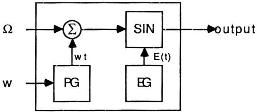
The operators can be connected in three different ways: additive, frequency modulation and composite sine wave.
FM synthesis
FM synthesis uses two operators in series. The first operator, the modulator, modulates the second operator via its modulation input. The name given to the second operator is the carrier. The modulator can feed back its output into its modulation data input;
Modulator and feedback
Carrier and Modulator
Additive synthesis
Additive synthesis connects two operators in parallel, adding both outputs together. This method of synthesis is not as interesting as FM synthesis, but it can generate good organ type sounds.
The simplified formula for the additive synthesis is:
Composite sine wave synthesis
Composite sine wave synthesis (CSW) may be used to generate speech or other related sounds by playing all voices simultaneously. When using this mode the card cannot generate any other sounds. This mode is not used because other methods have proved to provide better quality speech.
ALMSC Input / Output Map
The ALMSC is located at address 388H in the i/o space. The card decodes two addresses: 388H and 389H. The first address is used for selecting the register address and the second is used for writing data to the selected register. There also exists the possibility of using three other addresses: 218H, 288H and 318H. The port address is currently hardwired, but address jumpers may be added in the future so you may want to take into account the possibility of using different addresses when programming. Here is a register map of the ALMSC:
| REG | D7 D6 D5 D4 D3 D2 D1 D0 | |||||||
| 01 | WSE | TEST | ||||||
| 02 | TIMER-1 | |||||||
| 03 | TIMER-2 | |||||||
| 04 | RST | maskT1T2 | start/stopT2T1 | |||||
| 08 | CSM | SEL | ||||||
| 20-35 | AM | VIB | EG | KSR | MULTI | |||
| 40-55 | KSL | TL | ||||||
| 60-75 | AR | DR | ||||||
| 80-95 | SL | RR | ||||||
| A0-A8 | F-NUMBER(L) | |||||||
| B0-B8 | KON | BLOCK | F-NUM(H) | |||||
| BD | DEPAM | DEPVIB | R | BD | SD | TOM | TC | HH |
| C0-C8 | FB | C | ||||||
| E0-F5 | WS | |||||||
Because of the nature of the card, you must wait 3.3 µsec after a register select write and 23 µsec for a data write. Only the status register located at address 388H can be read.
For many parameters, there is one register per operator. However, there are holes in the address map so that the operator number cannot be used as an offset into the map. The operator offsets are as follows:
| Operator Address Offset | |||||||||
| Opr. | 1 | 2 | 3 | 4 | 5 | 6 | 7 | 8 | 9 |
| Off.(hex) | 00 | 01 | 02 | 03 | 04 | 05 | 08 | 09 | 0A |
| Opr. | 10 | 11 | 12 | 13 | 14 | 15 | 16 | 17 | 18 |
| Off.(hex) | 0B | 0C | 0D | 10 | 11 | 12 | 13 | 14 | 15 |
For example, the KSL/TL registers are at 40H-55H. If we wish to access the register for operator 8, we must write to register 49H (NOT 48H).
Register Reference
Test Register/WSE
This register must be initialized to zero before taking any action. The wave select enable/disable bit (WSE) is D5. If set to 1, the value in the WS register will be used to select the wave form used to generate sound. If the WSE is set to 0, the value in the WS register will be ignored and the chip will use a sine wave. (The available waveforms are detailed later in this section).
Timers
The timers are not wired on the card. However, the following information is included since the timers can be used to detect the presence of our card in the computer.
Timer-1 is an upward 8 bit counter with a resolution of 80 µsec. If an overflow occurs, the status register flag FT1 is set, and the preset value (address = 02) is loaded into Timer-1. Timer-2 (address = 03) is an upward 8 bit counter just like Timer-1 except that the resolution is 320 µsec.
N is the preset value and K is the timer constant equal to 0.08 for Timer-1 and 0.32 for Timer-2. Register address 04 controls the operation of both timers. ST1 and ST2 (start/stop T1 or T2) bits start or stop the timers. When the corresponding bit is 1 the counter is loaded and counting starts, but when 0 the counter is held.
The Mask bits are used to gate the status register timer flags. If a mask bit is 1 then the corresponding timer flag bit is kept low (0) and is active when the mask bit is cleared (0). The most significant bit (MSb) is called IRQ-RESET. It resets timer flags and IRQ flag in the status register to zero. All other bits in the control register are ignored when the IRQ- RESET bit is 1.
Status Register
Reading at address 388H yields the following byte of information:
D0 - D4 are unused.
D5 Timer 2 flag: Set to 1 when the preset time in Timer 2 has elapsed. The flag remains until reset.
D6 Same as D5, except for Timer 1.
D7 IRQ flag: set if D5 or D6 are 1.
As mentioned earlier, the timer interrupts are not connected, but the timers can be used to detect the presence of the board as follows:
-
Reset T1 and T2: write 60H to register 4.
-
Reset the IRQ: write 80H to register 4 (this step must NOT be combined with Step #1).
-
Read status register: read at 388H. Save the result.
-
Set timer-1 to FFH: write FFH to register 2.
-
Unmask and start timer-1: write 21H to register 4.
-
Wait (in a delay loop) for at least 80 µsec.
-
Read the status register and save the result.
-
Reset T1, T2 and IRQ as in steps #1 and #2.
-
Test the results of the two reads: the first should be 0, the second should be C0H. If either is incorrect, then an ALMSC board is not present. (NOTE: You should AND the result bytes with E0H as the unused bits are undefined.)
CSM/Keyboard Split
This register (address = 08) will determine if the card is to function in music mode (CSM=0) or speech synthesis mode (CSM=1) as well as the keyboard split point.
When using composite sine wave speech synthesis mode all voices should be in the KEY-OFF state. The bit NOTE-SEL (D6) is used to control the split point of the keyboard. When 0, the keyboard split is the second bit from the MSb (bit 8) of the F-Number. The MSb of the F-number is used when
NOTE-SEL = 1. This is illustrated in the following table:
NOTE-SEL = 0
| BLOCK/OCT | 0 | 1 | 2 | 3 | 4 | 5 | 6 | 7 | ||||||||
| FNUM(MSb) | X | X | X | X | X | X | X | X | ||||||||
| FNUM(8) | 0 | 1 | 0 | 1 | 0 | 1 | 0 | 1 | 0 | 1 | 0 | 1 | 0 | 1 | 0 | 1 |
| Split Num. | 0 | 1 | 2 | 3 | 4 | 5 | 6 | 7 | 8 | 9 | 10 | 11 | 12 | 13 | 14 | 15 |
NOTE-SEL = 1
| BLOCK/OCT | 0 | 1 | 2 | 3 | 4 | 5 | 6 | 7 | ||||||||
| FNUM(MSb) | 0 | 1 | 0 | 1 | 0 | 1 | 0 | 1 | 0 | 1 | 0 | 1 | 0 | 1 | 0 | 1 |
| FNUM(8) | X | X | X | X | X | X | X | X | X | X | X | X | X | X | X | X |
| Split Num. | 0 | 1 | 2 | 3 | 4 | 5 | 6 | 7 | 8 | 9 | 10 | 11 | 12 | 13 | 14 | 15 |
X = Ignored
AM/VIB/EG-TYP/KSR/Multiple
This group of registers (addresses 20H to 35H), one per operator, controls the frequency conversion factor and modulating wave frequencies corresponding to the frequency components of music.
The MULTI 4-bit field determines the multiplication factor applied to the input pitch frequency in the PG section. That is, an operator's frequency will automatically be multiplied according to the value in this field. The multiplication factors are given in the following table:
| MULTI | Factor |
| 0 | 1/2 |
| 1 | 1 |
| 2 | 2 |
| 3 | 3 |
| 4 | 4 |
| 5 | 5 |
| 6 | 6 |
| 7 | 7 |
| MULTI | Factor |
| 8 | 8 |
| 9 | 9 |
| 10 | 10 |
| 11 | 10 |
| 12 | 12 |
| 13 | 12 |
| 14 | 15 |
| 15 | 15 |
The operator output can then be expressed, with " ∂ " as the multiplication factor, as follows:
The KSR bit (position = D4) changes the rates for the envelope generator (EG). This parameter makes it possible to gradually shorten envelope length (increase EG rates) as higher notes on the keyboard are played. This is particularly useful for simulating the sound of stringed instruments such as piano and guitar, in which the envelope of the higher notes is noticeably shorter than the lower notes. The actual rate is then equal to the ADSR value plus an offset:
The KSR offset is specified in the following table:
| Rate | KSR=0 | KSR=1 |
| 0 | 0 | 0 |
| 1 | 0 | 1 |
| 2 | 0 | 2 |
| 3 | 0 | 3 |
| 4 | 1 | 4 |
| 5 | 1 | 5 |
| 6 | 1 | 6 |
| 7 | 1 | 7 |
| Rate | KSR=0 | KSR=1 |
| 8 | 2 | 8 |
| 9 | 2 | 9 |
| 10 | 2 | 10 |
| 11 | 2 | 11 |
| 12 | 3 | 12 |
| 13 | 3 | 13 |
| 14 | 3 | 14 |
| 15 | 3 | 15 |
The EG-Type activates the sustaining part of the envelope when the EG-Type is set (1). Once set, an operator's frequency will be held at its sustain level until a KEY-OFF is done.
The VIB parameter toggles the frequency vibrato (1 = on, 0 = off). The frequency of the vibrato is 6.4 Hz and the depth is determined by the DEP VIB bit in register 0BDH.
The AM parameter is similar to the VIB parameter except that it is an amplitude vibrato (tremolo) of frequency 3.7Hz. The amplitude vibrato depth is determined by the DEP AM bit in register 0BDH.
KSL/Total Level
These registers (addresses 40H to 55H, 1 per operator) control the attenuation of the operator's output signal. The KSL parameter produces a gradual decrease in note output level towards higher pitch notes. Many acoustic instruments exhibit this gradual decrease in output level. The KSL is expressed on 2 bits (value 0 through 3). The corresponding attenuation is given below:
| D7 | D6 | Attenuation |
| 0 | 0 | 0 |
| 1 | 0 | 1.5dB/oct |
| 0 | 1 | 3.0dB/oct |
| 1 | 1 | 6.0dB/oct |
The Total Level (TL) attenuates the operator's output. In FM synthesis mode, varying the output level of an operator functioning as a carrier results in a change in the volume of that operator's voice. Attenuating the output from a modulator will change the frequency spectrum produced by the carrier. In additive synthesis, varying the output level of any operator varies the volume of its corresponding voice. The TL value has a range of 0 through 63 (6 bits). To convert this value into an output level, apply the following formula:
ADSR
These values change the shape of the envelope for the specified operator by changing the rates or the levels. The attack (AR) and the decay (DR) rates are at addresses 60H to 75H (1 per operator). The Sustain Level (SL) and Release Rate (RR) are located at addresses 80H to 95H. All of these values are 4 bits in length (range 0 to 15). Refer to the register map for more information.
The attack rate (AR) determines the rising time for the sound. The higher the value in this register, the faster the attack.
The decay rate (DR) determines the diminishing time for the sound. The higher the value in the DR register, the shorter the decay.
The sustain level (SL) is the point at which the sound ceases to decay and changes to a sound having a constant level. The sustain level is expressed as a fraction of the maximum level. When all bits are set, the maximum level is reached. Note that the EG-Type bit must be set for this to have an effect.
The release rate (RR) determines the rate at which the sound disappears after a Key-Off. The higher the value in the RR register, the shorter the release time.
BLOCK/F-Number
These parameters determine the pitch of the note played. The Block parameter determines the octave while the F-Number (10 bits) further specifies the frequency. The following formula is used to determine the value of F-Number and Block:
In this formula, is the desired frequency (Hz) and "b" is the block value (0 to 7). Refer to Appendix C for a table of note frequencies.
The D5 bit in the register that contains the BLOCK information is called KEY-ON (KON) and determines if the specified voice (0 to 8) is enable (1) or disable (0). The lower bits of F-Number are at location A0H through A8H (1 per voice) and the 2 MSb are at positions D0 and D1 of addresses B0H to B8H.
| REG | D7 | D6 | D5 | D4 | D3 | D2 | D1 | D0 |
| A0H-A8H | F-Number2^{7}2^{6}2^{5}2^{4}2^{3}2^{2}2^{1}2^{0} | |||||||
| B0H-B8H | KEYON | Block2^{2}2^{1}2^{0} | F-Number2^{9}2^{8} | |||||
Rhythm/AM Dep/VIB Dep
This register allows for control over AM and VIB depth, selection of rhythm mode and ON/OFF control for various rhythm instruments. Bit D5 (R) is used to change the mode from melodic (0) to percussive (1). When in percussive mode, bits D0 through D4 are the KEY-ON/KEY-OFF controls for the rhythm instruments listed below. The KEY-ON bit in registers B6H, B7H and B8H must always be 0 when in percussive mode.
D0 Hi-Hat
D1 Cymbal
D2 Tom-Tom
D3 Snare Drum
D4 Bass Drum
The AM Depth is 4.8dB when D7 is 1 and 1dB when 0. The VIB Depth is 14 cents when D6 is 1, and 7 cents when zero. (A "cent" is 1/100th of a semi-tone.)
FeedBack/Connection
These two parameters influence the way the operators are connected together and the B factor in the feedback loop of the modulator. These parameters are assigned 1 per voice at locations C0H through C8H. The Connection bit (C) determines if the voice will be functioning in Additive synthesis mode (C = 1) of in Frequency modulation mode (C = 0). The other parameter, Feedback (FB), gives the modulation factor, B, for the feedback loop:
| 0 | 1 | 2 | 3 | 4 | 5 | 6 | 7 | |
| β | 0 | π/16 | π/8 | π/4 | π/2 | π | 2π | 4π |
Wave Select
The WS parameter enables the card to generate other kinds of wave shapes. This is done by changing the sine function of the specified operator. (Note that the WSE bit must be set in order to use this feature.) The addresses of this feature are E0H to F5H. The following figure gives the corresponding wave forms:
| D1 | D0 | Wave Form |
| 0 | 0 | Sine |
| 0 | 1 | Half-sine |
| 1 | 0 | Abs-sine |
| 1 | 1 | Pulse-sine |
This section explains the differences between the Ad Lib Gold Sound Adapter and the original Ad Lib Music Synthesizer Card as regards FM synthesis. A previous knowledge of the original Ad Lib card is assumed. If you are unfamiliar with the original card, you should first read the following section: "Programming the Synthesizer", which is reproduced from the original Programmer's Manual.
You can see from the register map below that the new FM section is quite similar to the original FM chip but with extra features added. Register Array 0 is accessed by writing to addresses x and x+1 (388H and 389H by default). Register Array 1 is accessed by writing to addresses x+2 and x+3 (38AH and 38BH by default). This scheme allows for complete compatibility with older software which recognizes only the original Ad Lib card.
All registers are cleared at reset. The TEST registers at 01 should be cleared or not accessed at all. Bits in the register map which are not designated should be left in their cleared state.
Register Array 0
Register Array 0 emulates the original chip and will be used as such by software written for the original card. However, there are several changes to be noted.
The Wave Select Enable bit (WSE, D5 at 01) no longer exists. Wave Select is now "on" permanently. Writing 1 to D5 at 01 has no effect so that compatiblity is thereby maintained.
The CSM bit (D7 at 08) found on the original chip is no longer present. Although this bit was documented on the original chip, it was nonfunctional. Compatibility is, therefore, not an issue.
The timers are now functional. How to program them is explained in the Timers section of Programming the Synthesizer.
Register Map, FM Array 0
| REG | D7 | D6 | D5 | D4 | D3 | D2 | D1 | D0 |
| 01 | TEST | |||||||
| 02 | TIMER-1 | |||||||
| 03 | TIMER-2 | |||||||
| 04 | RST | mask T1 T2 | start/stop T2 T1 | |||||
| 05 | ||||||||
| 08 | SEL | |||||||
| 20-35 | AM | VIB | EG | KSR | MULTI | |||
| 40-55 | KSL | TL | ||||||
| 60-75 | AR | DR | ||||||
| 80-95 | SL | RR | ||||||
| A0-A8 | F-NUMBER(L) | |||||||
| B0-B8 | KON | BLOCK | F-NUM(H) | |||||
| BD | DEP AM | DEP VIB | R | BD | SD | TOM | TC | HH |
| C0-C8 | SRL | STR | FB | C | ||||
| E0-F5 | WS | |||||||
Register Map, FM Array 1
| REG | D7 | D6 | D5 | D4 | D3 | D2 | D1 | D0 | |
| 01 | TEST | ||||||||
| 02 | |||||||||
| 03 | |||||||||
| 04 | CONNECTION SELECT | ||||||||
| 05 | NEW | ||||||||
| 08 | |||||||||
| 20-35 | AM | VIB | EG | KSR | MULTI | ||||
| 40-55 | KSL | TL | |||||||
| 60-75 | AR | DR | |||||||
| 80-95 | SL | RR | |||||||
| A0-A8 | F-NUMBER(L) | ||||||||
| B0-B8 | KON | BLOCK | F-NUM(H) | ||||||
| BD | |||||||||
| C0-C8 | SRL | STR | FB | C | |||||
| E0-F5 | WS | ||||||||
Each voice now has two bits which control stereo output: STL and STR (D5/D4 at C0-C8). Setting STL enables output to the left channel. Setting STR enables output to the right channel. Clearing both bits will result in no output for a given voice. However, for these bits to have effect, the NEW bit (explained in the next section) must be set. If NEW is not set (its default state), then the STL and STR bits are ignored and sound is output to both channels. This maintains compatibility with older software which ignores the existence of the stereo bits.
The stereo bits affect pairs of operators, which creates a particularity in percussive mode. The stereo bits in C7 simultaneously affect the Hi-Hat and Snare Drum; C8 affects the Tom-Tom and Cymbal similarly. The Bass Drum (C6) uses two operators and functions the same as a melodic voice.
The Wave Select has been expanded to 3 bits, thus allowing for a total of 8 different waveforms. The waveforms are shown below.
| D2-D0 | Waveform |
| 0 | Sine |
| 1 | Half-sine |
| 2 | Abs-sine |
| 3 | Pulse-sine |
| 4 | |
| 5 | |
| 6 | Square |
| 7 |
Register Array 1 is similar to Register Array 0 with some omissions and additions. The timer registers are unused or are used for other purposes. Register Array 1 does not offer percussive voices, so the bits relating to percussive mode are not present.
The SEL, DEP AM and DEP VIB bits are globally affective and so are found only in the first register array. Setting any one of these three bits will affect both register arrays.
The NEW bit (D0 at 05) enables the new features of the new chip. If this bit is zero, then writes to any other register in Register Array 1 will be blocked. When NEW is zero, Register Array 0 functions as if it were the original chip: the stereo bits will be ignored and the high bit of the wave select will be ignored.
IMPORTANT: All software should enable the NEW bit during its initialization sequence. However, it should clear the NEW bit when exiting. This is so that if an older piece of software is subsequently run, the card will be in the mode which emulates the original card.
The CONNECTION SELECT bits control the 4-operator voice, as explained in detail in the next section.
4-Operator Voices
A significant new feature of the FM section of the Ad Lib Gold card is the presence of 4-operator voices, which are capable of creating a large variety of rich timbres. To enable a 4-operator voice, you must set the appropriate bit in the CONNECTION SELECT register. The following table shows which bit corresponds to which 4-operator voice and the pair of 2-operator voices which correspond to the 4-operator voice.
Connection Select (05H, Register Array 1):
| D5 | D4 | D3 | D2 | D1 | D0 | |
| 4-op voice | 6 | 5 | 4 | 3 | 2 | 1 |
| 2-op voices | 3,6 | 2,5 | 1,4 | 3,6 | 2,5 | 1,4 |
| Array 1 | Array 0 | |||||
With 2-operator voices, the connection bit at C0-C8 specifies one of two possible methods for connecting the operators. With 4-operator voices, there are 4 methods of connecting the operators. This is done by using both connection bits of the pair of 2-operator voices involved. The following table shows the relationship between the 4-operator voice and its connection bits. The diagram below illustrates the connection methods.
Connection bit (C) addresses for 4-operator voices:
| 4-op voice | 1 | 2 | 3 | 4 | 5 | 6 |
| C addresses | C0,C3 | C1,C4 | C2,C5 | C0,C3 | C1,C4 | C2,C5 |
| Array 0 | Array 1 | |||||
Note that even if all six 4-operator voices are used, there are still three 2-operator voices available on Register Array 1 and three 2-operator or five percussive voices available on Register Array 0. The CONNECTION SELECT register allows you to selectively use 4-operator voices so that you can mix 2 and 4-operator voices as you wish.
The following table is a combination of the preceding two tables. You may find it useful for reference purposes.
| Connect Sel | D5 | D4 | D3 | D2 | D1 | D0 |
| 4-op voice | 6 | 5 | 4 | 3 | 2 | 1 |
| 2-op voices | 3,6 | 2,5 | 1,4 | 3,6 | 2,5 | 1,4 |
| C addresses | C2,C5 | C1,C4 | C0,C3 | C2,C5 | C1,C4 | C0,C3 |
| Array 1 | Array 0 | |||||
Feedback in a 4-operator voice is applied to the first operator only, as indicated by the loop around Operator 1 in the diagram below. The feedback value is determined by the value written in the register for the first register pair (Cx). The value in the second register pair (Cx+3) is ignored.
Similarly, the F-NUMBER, KON, and BLOCK parameters for a 4-operator voice are determined by the values written in the registers for the first register pairs (Ax and Bx). The values in the second register pairs (Ax+3 and Bx+3) are ignored.
Note that the state of the STL and STR bits for a 4-operator voice must be the same for both register pairs (Cx and Cx+3) or else the output of all four operators will be disabled. For example, if STL at C0 is 1 and STL at C3 is 0, then this 4-operator voice will not be output to the left channel.
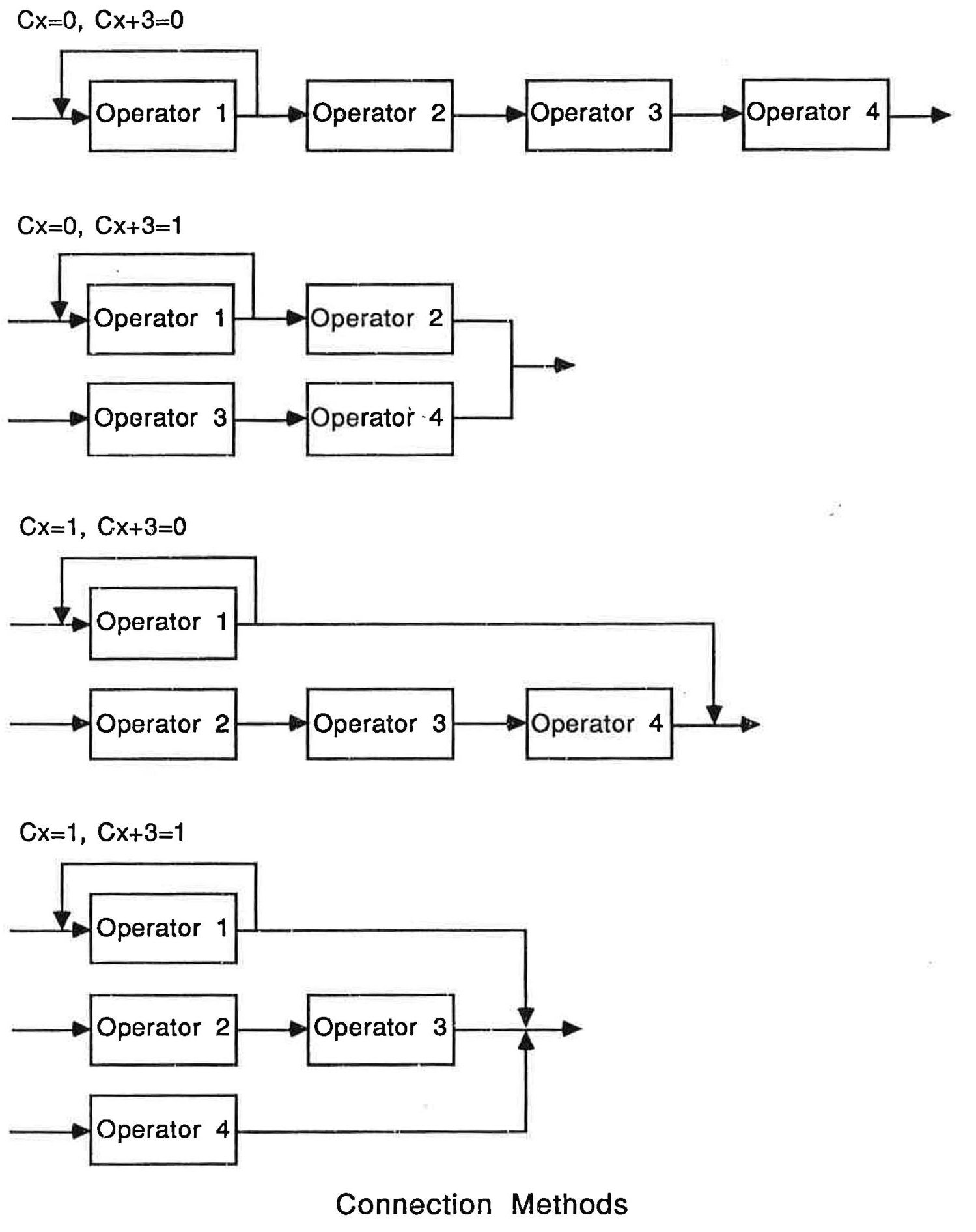
The digital I/O functions are handled by the YMZ263 chip, also known as the MMA. The MMA handles the following functions:
-
2 channels of digital audio input and ouput
-
MIDI input and output
-
Three high-speed timers
The digital I/O functions are accessed via three addresses. The first address is located four bytes past the address of FM Array 0 (38CH by default).
Accessing a MMA register is done in two steps:
-
write the index of the register to be accesed to the "register select" port, located at 38CH
-
write or read the desired value for the selected register, either in the channel 0 port, located at 38DH or in the Channel 1 port located at 38FH
A 470 nanosecond delay is necessary between read/write at any address of the MMA
| REG | D7 | D6 | D5 | D4 | D3 | D2 | D1 | D0 | ||
| 01 | - | TEST | ||||||||
| 02 | W | TIMER-0(L) | ||||||||
| 03 | W | TIMER-0(H) | ||||||||
| 04 | W | BASE COUNTER(L) | ||||||||
| 05 | W | TIMER1 | BASE COUNTER(H) | |||||||
| 06 | RW | TIMER2(L) | ||||||||
| 07 | RW | TIMER2(H) | ||||||||
| 08 | W | SBY | T2M | T1M | T0M | STB | ST2 | ST1 | ST0 | |
| 09 | W | RST | R | L | FREQ | PCM | P/R | GO | ||
| 0A | W | VOLUME CONTROL | ||||||||
| 0B | RW | PCM DATA | ||||||||
| 0C | W | ILV | DATA FMT | FIFO INT | MSK | ENB | ||||
| 0D | W | MSKPOV | MSKMOV | MDI TRS RST | MSKTRQ | MDI RCV RST | MSKRRQ | |||
| 0E | RW | MIDI DATA | ||||||||
Register Map, Channel 0
| REG | D7 | D6 | D5 | D4 | D3 | D2 | D1 | D0 | ||
| 01 | - | |||||||||
| 02 | W | |||||||||
| 03 | W | |||||||||
| 04 | W | |||||||||
| 05 | W | |||||||||
| 06 | RW | |||||||||
| 07 | RW | |||||||||
| 08 | W | |||||||||
| 09 | W | RST | R | L | FREQ | PCM | P/R | GO | ||
| 0A | W | VOLUME CONTROL | ||||||||
| 0B | RW | PCM DATA | ||||||||
| 0C | W | DATA FMT | FIFO INT | MSK | ENB | |||||
| 0D | W | |||||||||
| 0E | RW | |||||||||
Register Map, Channel 1
Register Reference
Status Register
Reading the port at address 38CH returns the following information:
| D7 | D6 | D5 | D4 | D3 | D2 | D1 | D0 |
| OV | T2 | T1 | T0 | TRQ | RRQ | FIF1 | FIF0 |
Status Byte
OV becomes 1 when a MIDI receive overrun error or a PCM/ADPCM record or playback overrun error occurs.
TO, T1 and T2 become 1 when the specified time elapses in the corresponding timer.
TRQ becomes 1 when the MIDI transmit FIFO buffer is empty.
RRQ becomes 1 when the MIDI receive FIFO buffer has data in it.
FIFO and FIF1 become 1 when the PCM/ADPCM FIFO reaches the status that was specified in FIFO INT. FIFO corresponds to channel 0; FIF1 to channel 1.
Register 00H: Test Register
Register #1, Channel 0 is used for testing the LSI. It should not be accessed.
Registers 02H - 07H: Timer Counters
Timer 0 (Registers #1 and 2, Channel 0) is a 16-bit programmable down counter with 1.88964 usec resolution. This constant will be referred to as clockFreq. the the following examples. The interrupt is triggered when the counter value reaches 0. The time t0, in usec, until IRQ is generated may be calculated as follows:
The BASE COUNTER (Register #4 and 5, Channel 0) is a 12-bit counter that supplies the period for each tick of TIMER1 and TIMER2. The base counter has a resolution of 1.89 usec. The period bc, in usec, may be calculated as follows:
baseFreq
Timer 1 (Register #5, Channel 0) is a 4-bit programmable down counter that is controlled by the base counter clock. The 4-bit value is placed in the high nibble of the register. The interrupt is triggered when the counter value reaches 0. The time t1, in usec, until IRQ is generated may be calculated as follows:
Timer 2 (Register #6 and 7, Channel 0) is a 16-bit programmable down counter that is controlled by the base counter clock. The interrupt is triggered when the counter value reaches 0. The time t2, in usec, until IRQ is generated may be calculated as follows:1
Transcribed as printed: the second term reads TIMER0(L), but it should read TIMER2(L). Provenance of the correction: (1) Timer 2 is a single 16-bit counter, so its value is reconstructed from its own high and low bytes — compare the t0 formula above, which pairs TIMER0(H) with TIMER0(L); (2) the paragraph immediately below states "TIMER2(L) must be read first as it is this read which triggers the latching mechanism," confirming TIMER2(L) is the intended low byte. The TIMER0(L) misprint appears identically across two independent OCR passes of the original scan, establishing that it originates in the 1992 printed source rather than in transcription. — Ed.
TIMER2 may be read to determine the count value. When TIMER2(L) is read the 16-bit count value is latched and the latched value of TIMER2(L) is output. Subsequently, when TIMER2(H) is read, the latched value of TIMER2(H) is output. (Latching a value means taking a "snapshot" of that value at a given moment.) TIMER2(L) must be read first as it is this read which triggers the latching mechanism.
Register 08H: Timer Control
| D7 | D6 | D5 | D4 | D3 | D2 | D1 | D0 |
| SBY | T2M | T1M | T0M | STB | ST2 | ST1 | ST0 |
Register #8: Channel 0
Stand-by Mode
Setting SBY to 1 reduces the internal clock frequency in order to minimize power consumption. This must be set to 0 when doing any I/O operations.
Timer Interrupt Masks
Timer Interrupt Masks Setting T0M, T1M or T2M disables the interrupt generated by the corresponding timer. Hence, the bit must be cleared if you wish to use the interrupt timer.
Timer Controls
ST0, ST1, ST2 and STB (base counter) contol the start and stop of each timer. Setting a bit loads the reload value and starts counting down. Clearing the bit stops the timer.
Register 09H: Playback and Recording Control
| D7 | D6 | D5 | D4 | D3 | D2 | D1 | D0 |
| RST | R | L | FREQ | PCM | P/R | GO | |
Register #9: Channels 0 & 1
Reset PCM/ADPCM
RST bit is used to reset PCM and ADPCM playback for the channel. Resetting a channel clears the FIFO buffers and resets the FIFO flags. In order for reset to operate properly, all other bits should be 0. The sequence for a channel reset should then be: 1) write 80H to register 9 2) write the desired values to register 9.
Select Output Channel
Output Channel Setting L or R enables output from the left or right channel respectively. Clearing the bit disables output.
Select Frequency
FREQ selects the PCM/ADPCM frequency as indicated below:
| FREQ | Sampling Frequency(KHz) | |
| PCM Mode | ADPCM Mode | |
| 0 | 44.1 | 22.05 |
| 1 | 22.05 | 11.025 |
| 2 | 11.025 | 7.35 |
| 3 | 7.35 | 5.5125 |
PCM/ADPCM Selection
Setting PCM selects PCM mode (data is not compressed). Clearing PCM selects ADPCM mode (data is compressed to 4-bits).
Select Record/Playback
Clear P/R to record; set it to playback.
Start/Stop Record/Playback
In playback, the FIFO buffers should never be empty when the GO bit is set. To start playback, the proper procedure is: 1) write data into the FIFO buffer for the channel. The FIFO should be filled to a level exceeding the FIFO interrupt level (see register 0CH description) 2) Set the GO bit to start playback.
Register 0AH: Output Volume Control
VOLUME CONTROL (Register #0Ah, both channels) sets the output attenuation value. A value of 0 is the minimum output volume, a value of FF is the maximum ouput volume.
Register 0BH: PCM/ADPCM Data
Register #0Bh (both channels) is used for writing data into the FIFO buffer and reading data from the FIFO buffer. Each channel has its own buffer. Data written into this register is transferred into the FIFO buffer, and data transferred from the FIFO buffer is written into this register. In PCM mode, 12-bit data is accessed in one or two passes. The data format for this access follows the specification of the FORMAT register. In ADPCM mode, each access inputs or outputs two 4-bit data. The high 4 bits and the low 4 bits are each ADPCM data. The high data is followed immediately by the low data.
Register 0CH: Sampling Format and Control
| D7 | D6 | D5 | D4 | D3 | D2 | D1 | D0 |
| ILV | DATA FORMAT | FIFO INT | MSK | ENB | |||
Register #0Ch: Channels 0 & 1
Interleaving
Setting ILV (Channel 0 only) to 1 will cause the chip to do interleaving. Data will be alternately input/output from each channel. Channel 0 initiates the transfer. ENB must be 1 for both channels, otherwise the data transfer is not performed. Both channels operate in the same mode so that the P/R,FREQ and GO bits will be controlled by the values set for channel 0.
Set Data Format
There are 3 possible data formats for sampling input and output. The format is selected by writing 0,1 or 2 to the DATA FORMAT register. "3" is an invalid format... This is ignored in ADPCM mode.
Format 0 is an 1-byte format which contains the 8 most significant bits of the sample.
Format 1 is a 2-byte format. The first byte contains the 8 least significant bits. The lower nibble of the second byte contains the 4 most significant bits of the sample. The MSB of the sample is repeated in all bits of the upper nibble.
Format 2 is a 2-byte format as well. The upper nibble of the first byte contains the 4 LSBs of the sample. The lower nibble is zero. The second byte contains the 8 MSB's.
| FORMAT | PCM Data Byte 1 | PCM Data Byte 2 |
| 0 | MSB b10 b9 b8 b7 b6 b5 b4 | There is no 2nd byte |
| 1 | b7 b6 b5 b4 b3 b2 b1 b0 | MSB MSB MSB MSB MSB b10 b9 b8 |
| 2 | b3 b2 b1 b0 0000 | MSB b10 b9 b8 b7 b6 b5 b4 |
PCM Data Formats
Set FIFO Interrupt
The FIFO INT register is used to specify when an interrupt will be generated while the 128-byte FIFO buffer is being filled or emptied. The following table documents the possible interrupt points.
| FIFO INT | Interrupt Generation Point(bytes) |
| 0 | 112 |
| 1 | 96 |
| 2 | 80 |
| 3 | 64 |
| 4 | 48 |
| 5 | 32 |
| 6 | 16 |
| 7 | Prohibited |
FIFO Interrupt Mask
Setting MSK disables the FIFO interrupt.
DMA Mode Specification
Set ENB to enable the DMA mode. Clear ENB when not using DMA to transfer data.
Register 0DH: MIDI and Interrupt Control
| D7 | D6 | D5 | D4 | D3 | D2 | D1 | D0 |
| MSKPOV | MSKMOV | MDITRSRST | MSKTRQ | MDIRCVRST | MSKRRQ |
Register #0Dh: Channel 0
Mask Digital Overrun Error Set POV to disable interrupt signals generated by overrun errors during PCM/ADPCM recording and playback.
Mask MIDI Overrun Error Set MOV to disable interrupt signals generated by overrun errors during MIDI reception or transmission.
Reset MIDI transmit circuit Set MDI TRS RST to 1 to reset the MIDI transmit circuit and clear the MIDI transmit FIFO buffer. Zero MDI TRS RST to terminate the reset status.
Mask MIDI transmit FIFO interrupts
Mask MIDI transmit FIFO interrupts Set MSK TRQ to disable interrupt signales generated by the MIDI transmit FIFO. When interrupts are enabled, an interrupt is generated when the MIDI transmit FIFO buffer is emptied.
Reset MIDI Receive Circuit Set MDI RCV RST to 1 to reset the MIDI receive circuit and clear the MIDI receive FIFO buffer. Zero MDI RCV RST to terminate the reset status.
Mask MIDI Receive FIFO Interrupts Set MSK RRQ to disable interrupt signals generated by the MIDI receive FIFO buffer. When interrupts are enabled, an interrupt is generated on reception of a MIDI byte.
Register 0EH: MIDI Data
This register is used for writing data into the MIDI FIFO buffer an reaing data from the MIDI FIFO buffer. Data written in this register is ransferred to the transmit FIFO buffer and data transferred from the receive FIFO buffer can be read from this register.
MMA Programming Tips
-
Reset a MMA channel after each sample (using the RST bit in register 9), after stopping the sample playback. This makes sure that the FIFO buffer for the channel is emptied.
-
In playback mode, when processing a FIFO interrupt, a situation occurs where your application is filling in the FIFO while the playback mechanism is emptying the FIFO at the same time. In some cases this can cause "false triggers" of the FIFO interrupt. In order to avoid this, a simple trick is to temporarily lower the FIFO level, while your application fills in the FIFO, and restore the original level before leaving the interrupt procedure.
-
A similar situation can occur in recording mode.
-
To avoid the same situation during playback and recording using DMA transfers, you can double-check if the interrupt is valid by reading the DMA controller's counters or status register. they should indicate that data transfer is over.
-
The MMA FIFO buffers should never be left to empty themselves during playback (tht is wen GO bit is set) This implies that the FIFO buffers should be filled to a level exceeding the FIFO interrupt level before the GO bit is set.
Special care should be taken during high-speed transfers (44.1K, 12 bit stereo samples, for example) on slower computers.
-
All masks (mask T2, T1, T0, FIFO, POV, MOV, TRQ and RRQ) have no effect whatsoever on the status register. They are only used to disable the hardware interrupt.
-
Respect the 470ns delay between writes to the MMA registers.
Appendix: YAMAHA Gold Sound Standard (GSS)
The Gold Sound Standard specification: MMA, OPL3 and mixer/set-up implementation.
YAMAHA Gold Sound Standard
March 17,1992
Contents
Introduction ...1
Overview ...2
GSS Implementation...3
MMA: Digital Audio, MIDI, and Game Port ...4
OPL3: FM Synthesis ...6
Mixer and Set-up Section ...9
Software Issues ...11
Mixer and Set-up Function
Implementation...12
Access Method ...12
Status Register ...13
Index Register Map ...14
Register Reference ...15
Conclusion ...28
Introduction
The rapid evolution of multimedia has necessitated an audio standard to be defined. Although Windows alleviates some of the need for compatibility, it is important that an audio standard is established for DOS, game, and "edutainment" applications. The implementation of an audio multimedia standard lessens the concerns of both hardware and software developers.
This document describes recommended procedures and practices for implementing multimedia audio hardware using the "Magic" chip set from YAMAHA. By conforming to the Gold Sound Standard, hardware manufacturers can be assured that software written for Gold Sound Standard compatible cards will run on their product.
The Gold Sound Standard is a hardware implementation specification, as well as the requirements of hardware compatibility at the register level for the mixer and set up functions. This ensures that software, which writes directly to the hardware, will run on any Gold Sound Standard implementation. This also means that any Gold Sound Standard driver kit for DOS or Windows will be capable of driving any Gold Sound Standard hardware. The Gold Sound Standard provides a safe development path for both software and hardware designers.
Overview
The Gold Sound Standard (GSS) is composed of the YAMAHA "Magic" chip set and a form of mixer and set up circuitry. In the case of the YAMAHA "Magic" chip set, this document will summarize its functions. A more detailed reference for the individual registers of the "Magic" chip set may be found in the YAMAHA reference manual for the particular chip.
Only the minimum requirements are defined in this document. The individual hardware designer may implement additional features. The GSS provides the necessary functionality to be Level 1 MPC compatible.
The "Magic" chip set is designed as a highly integrated solution to developing a Level-1 MPC compatible audio subsystem. The following sections illustrate design concerns when using the "Magic" chip set. They also provide the I/O register map requirements to be Gold Sound Standard compatible.
GSS Implementation
The basic features of GSS compatible hardware are a MIDI port, microphone input, stereo input/output, joystick input, and a mixer to produce the stereo audio output. Optionally, a SCSI interface may be implemented for use with CD-ROM drives. A hardware design conforming to the GSS will allow software that directly accesses the hardware to run on all GSS compatible cards. The design concerns are minimized by implementing the "Magic" chip set, which includes the YMZ263 (MMA) Multimedia Audio LSI, the YMF262 (OPL3) Advanced Algorithm Synthesizer LSI, and the YAC512-M Stereo Serial DAC. The following figure illustrates the hardware components of a typical Level 1 multimedia PC using the "Magic" chip set.
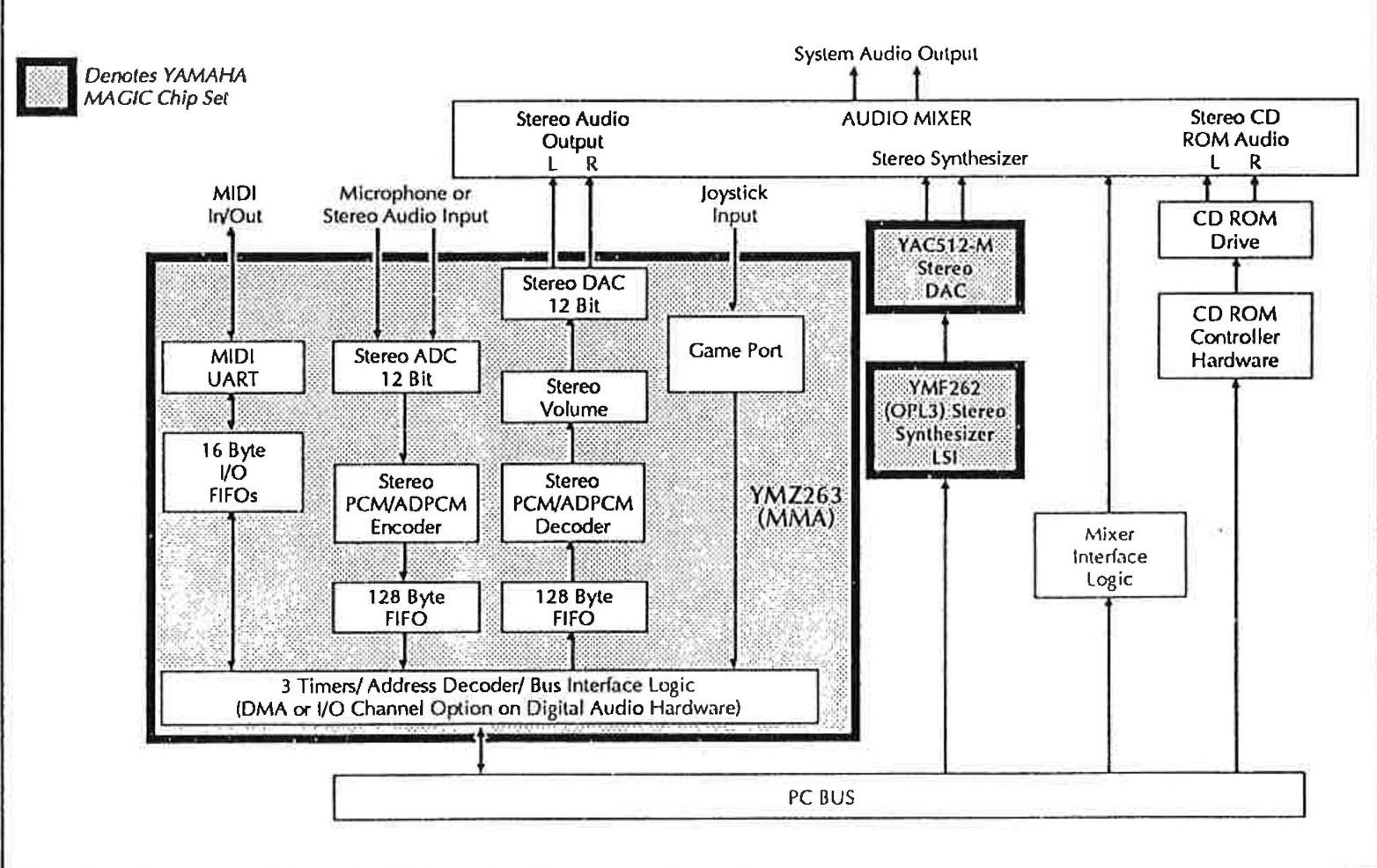
MMA: Digital Audio, MIDI, and Game Port
The MMA integrates a stereo digital audio, game port, and MIDI interface into one LSI. The MMA also contains internal bus decode logic, two DMA channels, and two FIFOs. The internal block diagram illustrates the various portions of control circuitry.
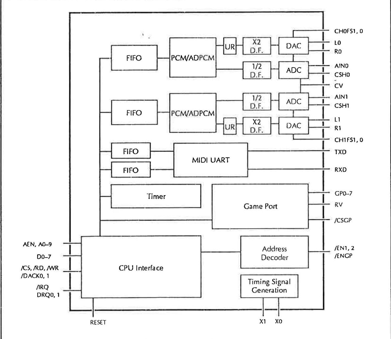
The CPU interface is directly connectable to the address, data, and I/O control lines of the PC bus. The interrupt line is connected to the PC bus and may either be asserted when there is data in the input FIFOs, when the output FIFOs are able to receive more data, or if a timer interrupt is generated.
The DMA channels may be programmed to provide two methods of operation, allowing simultaneous record and playback. The first method uses a separate DMA channel for each channel. The second method is to interleave channel information using one DMA.
A PAL device may be used to decode jumper block settings, allowing DMA channel and IRQ level selection.
The direct ISA bus interface of the MMA contains an address decoder for built in fixed addresses. The I/O address the MMA will respond to is determined by the state of the /EN1, /EN2, and /ENGP signals. The recommended default I/O address for the MMA is from 38CH to 38FH (Channel 0: 38CH-38DH, Channel 1: 38EH-38FH). The MMA uses two port addressing for each channel. The first address of a channel is the address register, which is used to access the desired internal register. The second register is the data register. The data written to this register will be sent to the register specified by the index written to the address register.
The two inputs to the wave audio section of the MMA are a low impedance stereo microphone or a high impedance stereo audio. These inputs are A/D converted at twice the selected sampling frequency and decimated before being fed into the PCM/ADPCM encoder. External capacitors are attached to pins CSH1 and CSH2, which stabilize the analog signals during sample hold operations. A reference center voltage for the A/D converter is supplied through the CV pin of the MMA.
The buffered PCM/ADPCM decoder output is amplified and over sampled at twice the selected frequency (except for 44.1 kHz PCM mode) before passing through the DAC. The DAC output signals are fed through a series of operational amplifiers ending with a low pass reconstruction filter before final output.
The MMA contains a MIDI subsystem with three timers, an asynchronous UART, and two 16 byte FIFOs for sending and receiving MIDI data. The MIDI output channel (TXD) is inverted and sent through an external 5 mA current loop to the external MIDI output connector. The external MIDI input connector's RXD signal is optically isolated to avoid ground loops. An optional MIDI thru port may be added by transferring the MIDI input signal through two inverters out an additional MIDI output port.
The game port interface of the MMA uses internal voltage comparison circuitry to isolate changes in the signals from the game port connector.
OPL3: FM Synthesis
The FM synthesis is produced by the OPL3 and uses the YAC512-M stereo DAC for output. The OPL3 is backward compatible with the YM3812 (OPL2) used in most popular PC audio cards, yet offers much higher quality synthesized sound. The OPL3 was designed to be directly controlled by software. The following diagram illustrates the internal functions of the OPL3.
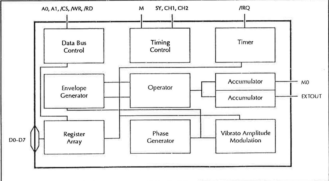
The OPL3 requires a 14.3127 MHz oscillator, which is taken directly from the PC bus. The address, data, and I/O control lines are also taken directly from the PC bus.
The recommended default base address of the OPL3 is 388H. The OPL3 also uses two port addressing for each channel and the internal register access is identical to the procedure used with the MMA. Channel 0 will be accessed at 388H and Channel 1 at 38AH.
The internal block diagram of the YAC512-M is shown below.
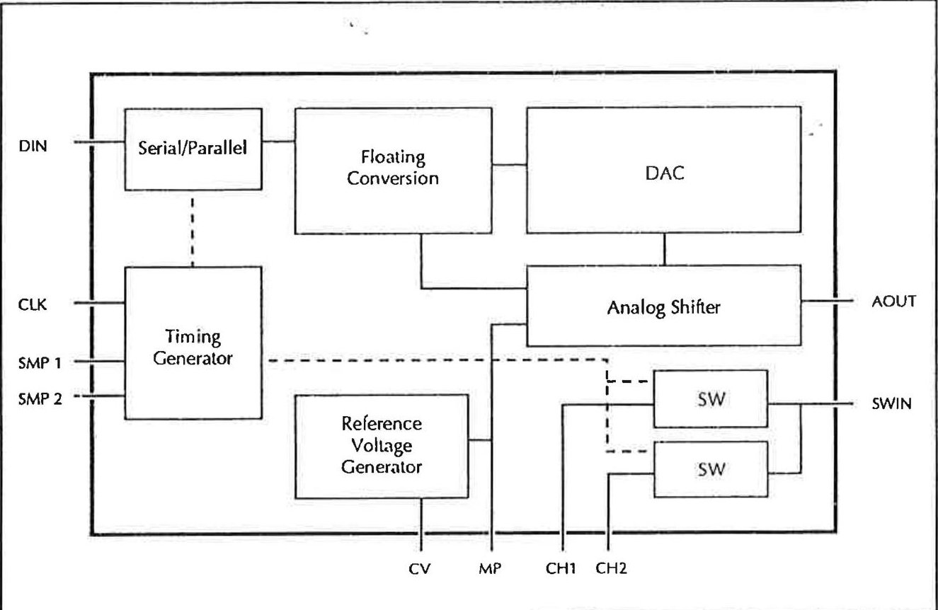
The serial data output and sample/hold channel signals are directly connected to the YAC512-M. The serial data between the OPL3 and the YAC512-M is synchronized using the OPL3's SY clock signal. This data is then latched when the channel sampling lines of the OPL3 fall.
The data is converted to floating point with the mantissa being processed by the DAC and the exponent by the analog shifter. This process produces effectively 16 bit resolution. The data is then converted into a D/A voltage which is sent out the AOUT terminal. This signal passes through a buffer operational amplifier for sample holding and is used for channel 1/2 common input.
The YAC512-M converts the digital serial stream into an analog signal. The YAC512-M requires external capacitors for stabilizing the analog output. The stereo output of the YAC512-M is ready for mixing with the MMA's stereo audio output. The block diagram below illustrates the simple connections between the OPL3 and the YAC512-M.
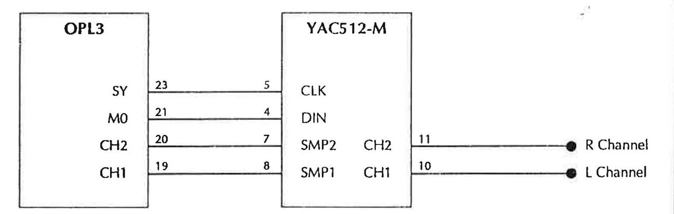
Mixer and Set-up Section
The mixer section is where the hardware designer may differentiate their audio implementation. The Gold Sound Standard implementation allows software to control the individual volumes of the mixer inputs.
The GSS allows for relocation of the MMA and OPL3. Software should not assume an absolute address. This document will use the default base address of the OPL3 (388H) and the MMA (38CH). The mixer section may be accessed by outputting an invalid index address to the second channel address register of the OPL3.
This access method uses the second channel of the OPL3 for the mixer registers. When the mixer registers are enabled, an index into the internal mixer registers is written to 38AH, or OPL3 base address +2, with the desired register data written to 38BH, or OPL3 base address +3.
In order to avoid the problem of hardware reentrance when accessing the mixer registers the software must push the flags and disable interrupts. Then by writing a value of FFH to port 38AH, or OPL3 base address +2, the hidden mixer registers will appear on top of the second channel of the OPL3.
The next output to port 38AH or OPL3 base address +2 will be an index into the internal registers. The specified internal register is ready for read/write operations. Multiple reads or writes may be made without continually resetting the address register. Once all accesses are complete, the internal register access is disabled by writing a FEH to port 38AH, or OPL3 base address +2. This access method is illustrated by the listing below.
| PUSHF | ; Push the CPU status flags. | |
| CLI | ; Disable Interrupts | |
| OUT | OPL3_base+2,FFH | ; Switch to mixer register access |
| OUT | OPL3_base+2,02H | ; Select register 2,Left Smpl Gain |
| OUT | OPL3_base+3,34H | ; Set gain level to 34H |
| ... | ||
| OUT | OPL3_base+2,FEH | ; Close access to internal mixer ; registers. |
| POPF | ; Restore interrupt status. |
This approach minimizes the address space occupied by the GSS implementation and reduces the risk of hardware conflicts with other resources.
The implementation allows access to the address and data I/O registers of the first channel of the OPL3, while accessing the internal mixing registers. The address decoding being handled by the mixer section should have no influence on the operation of the second channel of the OPL3.
As is the case with all other aspects of the GSS hardware, special care must be taken for the possibility of reentrance when separate applications access the mixer section and the OPL3 chip simultaneously. This is discussed in the section entitled "Software Issues" below.
Software Issues
In the GSS architecture, hardware reentrance may be possible. Applications may be using the MMA to record and play back samples while the timer or MIDI functions are being used by other applications. Multiple operations are required to access the OPL3 and the MMA. There is a possibility of an interrupt occurring during these accesses, which would cause problems.
In a single-task system (such as DOS), this reentrance may be handled by disabling interrupts during accesses to the GSS hardware.
This reentrance may be handled through the use of an asynchronous queue manager, which would handle mixer register requests when appropriate.
The GSS hardware implementation will allow any standard PCM wave data files to be played, provided it is sampled at the supported frequencies of the MMA.
A method of verifying GSS audio hardware is to write a signature value to the PCM data registers of Channel 1 and 2 of the MMA. If the value read back matches the value written, the audio hardware is GSS compatible.
Mixer and Set-up Function Implementation
The internal mixing register will have read/write capability with the exception of the supported features register. The supported features register will be read only.
Access Method
The mixer and set-up registers, when enabled, use two port addressing like the MMA and OPL3. The first address being an index into the register map with the next address for data.
A delay of 450 microseconds is recommended after writing to the output volume registers (04H-08H).
A delay of 5 microseconds is recommended after writing to the mixing volume registers and channel/IRQ registers (09H-15H).
In order to ensure these delays, the mixer access status register should be polled.
While writing the mixer registers to memory the mixer must not be accessed. This is achieved by polling the mixer register write status bit, checking for a "0".
Status Register
The index address register of the mixer is used as a status register. Reading the status register returns information as defined in the following figure.
| Status Register | ||||||||
| D7 | D6 | D5 | D4 | D3 | D2 | D1 | D0 | Function |
| X | Indicates FM Interrupt | |||||||
| X | Indicates Sampler Interrupt | |||||||
| X | X | X | X | Reserved | ||||
| X | Mixer Register Access Status | |||||||
| X | Mixer Register Write Status | |||||||
D0. This bit provides interrupt information for the FM portion. When bit D0 is set to 0, it indicates the FM portion of the hardware has generated an interrupt.
D1. This bit provides interrupt information for the sampling portion. When bit D1 is set to 0, it indicates that the sampling portion of the hardware has generated the interrupt.
D2-D4 These bits are reserved.
D6. This bit indicates the mixer register write status. If bit D6 is set the card is currently writing to a mixer register.
D7. This bit indicates the card is currently writing its registers to memory. This is useful for notebook and portable devices utilizing power saving features.
Index Register Map
The following figure defines the mixer index and data register map. The index value is written to the address register of the mixer to access the desired register. The data is then written to the data register of the mixer.
| Mixer and Set-up Index Register Map | ||
| Index | Read/Write | Description |
| 00 | R | ID/Feature Register |
| 02 | R/W | Left Channel Sampling Gain |
| 03 | R/W | Right Channel Sampling Gain |
| 04 | R/W | Left Channel Output Volume |
| 05 | R/W | Right Channel Output Volume |
| 06 | R/W | Bass Output |
| 07 | R/W | Treble Output |
| 08 | R/W | Output Mode |
| 09 | R/W | Left Channel FM Volume |
| 0A | R/W | Right Channel FM Volume |
| 0B | R/W | Left Sampling Volume |
| 0C | R/W | Right Sampling Volume |
| 0D | R/W | Left Auxiliary Volume |
| 0E | R/W | Right Auxiliary Volume |
| 0F | R/W | Microphone Volume |
| 11 | R/W | Audio Selection |
| 13 | R/W | Audio IRQ/DMA Select-Channel 0 |
| 14 | R/W | DMA Select Channel 1 |
| 15 | R/W | Audio Relocation |
The register map is a complete set of registers required to be compatible with the GSS. These are the minimum features required for mixer implementation on a GSS compatible audio card.
Register Reference
0H: ID/Feature Register
This read-only register provides information on supported features of the board. The bit functions are identified in the following figure.
| 0H: ID/Feature Register | ||||||||
| D7 | D6 | D5 | D4 | D3 | D2 | D1 | D0 | Function |
| X | X | X | X | X | Reserved | |||
| X | Surround Sound Option | |||||||
| X | SCSI Option | |||||||
| X | Reserved=1 | |||||||
02H: Left Channel Sampling Gain
The left channel sampling gain is controlled by values written to this register. There are 256 possible values. The amount of gain and step is dependent on the mixer implementation. The recommended gain implementation is computed by the following equation:
Gain = (Register Value * 10)/256
The bit functions of this register are identified in the following figure.
| 02H: Left Channel Sampling Gain | ||||||||
| D7 | D6 | D5 | D4 | D3 | D2 | D1 | D0 | Function |
| X | X | X | X | X | X | X | X | Left Channel Output Gain |
03H: Right Channel Sampling Gain
The right channel sampling gain is controlled by values written to this register. There are 256 possible values. The amount of gain and step is dependent on the mixer implementation. The recommended gain implementation is computed by the following equation:
Gain = (Register Value * 10)/256
The bit functions of this register are identified in the following figure.
| 03H: Right Channel Sampling Gain | ||||||||
| D7 | D6 | D5 | D4 | D3 | D2 | D1 | D0 | Function |
| X | X | X | X | X | X | X | X | Right Channel Output Gain |
04H: Left Channel Output Volume
This read/write register controls the overall left channel output volume. The bit functions of this register are identified in the following figure.
| 04H: Left Channel Output Volume | ||||||||
| D7 | D6 | D5 | D4 | D3 | D2 | D1 | D0 | Function |
| X | X | X | X | X | X | Left Channel Output Volume | ||
| X | X | Reserved=1 | ||||||
The left channel volume may range from 0 to 64 dB. The recommended volume range is from +6 dB to -64 dB, in two dB steps. The decibel values are listed in the following figure.
| Decibels | D5-D0 |
| 6 | 3F |
| -62 | 1D |
| -80 | 0 |
05H: Right Channel Output Volume
This read/write register controls the overall right channel output volume. The bit functions of this register are identified in the following figure.
| 05H: Right Channel Output Volume | ||||||||
| D7 | D6 | D5 | D4 | D3 | D2 | D1 | D0 | Function |
| X | X | X | X | X | X | Right Channel Output Volume | ||
| X | X | Reserved=1 | ||||||
The right channel volume may range from 0 to 64 dB. The recommended volume range is from +6 dB to -64 dB, in two dB steps. The decibel values are listed in the following figure.
| Decibels | D5-D0 |
| 6 | 3F |
| -62 | 1D |
| -80 | 0 |
06H: Bass Output
This read/write register controls the bass output with a range of values from 0 to 16. The bit functions of this register are identified in the following figure.
| 06H:Bass Output | ||||||||
| D7 | D6 | D5 | D4 | D3 | D2 | D1 | D0 | Function |
| X | X | X | X | Bass Output | ||||
| X | X | X | X | Reserved=1 | ||||
The recommended decibel range is from +15 dB to -12 dB in 3 dB steps. The decibel values are listed in the following figure.
| Decibels | D3-D0 |
| 15 | F |
| 15 | B |
| 0 | 6 |
| -12 | 2 |
| -12 | 0 |
07H: Treble Output
This read/write register controls the treble output with a range of values from 0 to 16. The bit functions of this register are identified in the following figure.
| 07H: Treble Output | ||||||||
| D7 | D6 | D5 | D4 | D3 | D2 | D1 | D0 | Function |
| X | X | X | X | Treble Output | ||||
| X | X | X | X | Reserved=1 | ||||
The recommended range is from +12 dB to -12 dB, in 3 dB steps. The decibel values are listed in the following figure.
| Decibels | D3-D0 |
| 12 | F |
| 12 | A |
| 0 | 6 |
| -12 | 2 |
| -12 | 0 |
08H: Output Mode
This read/write register controls the final output. The final output uses the input and output of the mixer. The bit functions of this register are identified in the following figure and defined below.
| 08H:Output Mode | ||||||||
| D7 | D6 | D5 | D4 | D3 | D2 | D1 | D0 | Function |
| X | X | X | Source of Final Output | |||||
| X | X | Type of Effect | ||||||
| X | Mute | |||||||
| X | X | Reserved=1 | ||||||
D2-D0. These bits determine the channels to be selected for the final output. If only one output channel is selected, it will be directed out to both channels. The following figure defines the signal configurations.
| D2 | D1 | D0 | Channels |
| 1 | 1 | 0 | Left and Right |
| 1 | 0 | 0 | Right Only |
| 0 | 1 | 0 | Left Only |
D4-D3. These bits determine the output effect. The following figure defines the signal configurations.
| D4 | D3 | Type of Effect |
| 1 | 1 | Spatial Stereo |
| 1 | 0 | Pseudo Stereo |
| 0 | 1 | Linear Stereo |
| 0 | 0 | Forced Stereo |
D5. This bit enables or disables mute.
D7-D6. These bits are reserved and set to 1.
09H-0FH
Registers 09H through 0FH are the individual mixing controls, and comprise the mixer section of the audio card. The following figure provides descriptions for these registers.
| 09H-0FH | |
| Register | Description |
| 09H | Left Channel FM Volume |
| 0AH | Right Channel FM Volume |
| 0BH | Left Sampling Volume |
| 0CH | Right Sampling Volume |
| 0DH | Left Auxiliary Volume |
| 0EH | Right Auxiliary Volume |
| 0FH | Microphone Volume |
There are 128 possible linear volume levels, ranging from silent (80H) up to a maximum gain (0FFH). If values less than 80H are written to this register, a negative voltage signal (negative polarity) would result. This may cancel out another signal and should be avoided. The following figure specifies the volume range.
| Value | Volume Range |
| FFH | Maximum Volume |
| 80H | Minimum Volume |
| 00H | Negative Maximum Volume |
11H: Audio Selection
This read/write register controls the antialiasing filters (input/output) and the auxiliary input. The same antialiasing filter is used for sampling and playback. The bit functions of this register are identified in the following figure and defined below.
| 11H: Audio Selection | ||||||||
| D7 | D6 | D5 | D4 | D3 | D2 | D1 | D0 | Function |
| X | Right Channel Filter | |||||||
| X | Left Channel Filter | |||||||
| X | Auxiliary Input Control | |||||||
| X | Internal Speaker Mixer | |||||||
| X | X | X | X | Reserved | ||||
D0. This bit is used to set the filter for Right Channel. When this bit is set to 1, the filter is set for recording. When set to 0, the filter is set for playback.
D1. This bit is used to set the filter for Left Channel. When this bit is set to 1, the filter is set for recording. When set to 0, the filter is set for playback.
D2. This bit controls the auxiliary input. When this bit is set to 1 forces the stereo input to monophonic to be sampled on Left Channel. When set to 0, the auxiliary input to stereo is restored.
D3-D4. These bits are reserved.
D5. This bit enables or disables the internal speaker of the PC to be mixed with the final audio output.
D7-D6. These bits are available.
13H: Audio IRQ/DMA Select--Left Channel
This read/write register controls the interrupt and DMA functionality of the FM and sampling features. The bit functions of this register are identified in the following figure and defined below.
| D7 | D6 | D5 | D4 | D3 | D2 | D1 | D0 | Function |
| X | X | X | Select Interrupt | |||||
| X | Enables Audio Interrupt | |||||||
| X | X | X | Selects DMA | |||||
| X | Enables Left Channel DMA |
D2-D0. These bits control the IRQ selection, as defined in the following figure.
| Interrupt Select | IRQ |
| 0 | 3 |
| 1 | 4 |
| 2 | 5 |
| 3 | 7 |
| 4 | 10 |
| 5 | 11 |
| 6 | 12 |
| 7 | 15 |
D3. When this bit is set to 1, audio interrupts are enabled.
D6-D4. These bits select the DMA line for Left Channel, as defined in the following figure.
| DMA Select | DMA Line |
| 0 | 0 |
| 1 | 1 |
| 2 | 2 |
| 3 | 3 |
D7. When this bit is set to 1, the DMA for Left Channel is enabled.
14H: DMA Select Right Channel
The DMA select Right Channel register controls the DMA for Right Channel and is identical to the Left Channel register except for the IRQ information. The bit functions of this register are identified in the following figure and defined below.
| 14H: DMA Select Channel 1 | ||||||||
| D7 | D6 | D5 | D4 | D3 | D2 | D1 | D0 | Function |
| X | X | X | X | X | Reserved | |||
| X | X | Selects DMA | ||||||
| X | Enables Right Channel DMA | |||||||
D4-D0. These bits are reserved.
D6-D5. These bits select the DMA line for Right Channel, as shown in the following figure.
| DMA Select | DMA Line |
| 0 | 0 |
| 1 | 1 |
| 2 | 2 |
| 3 | 3 |
D7. When this bit is set to 1, the DMA for Right Channel is enabled.
15H: Audio Relocation
The audio relocation register provides the flexibility of relocating the I/O map of the FM banks and the sampling channels. The value written to this register is the port address divided by eight, which will force the location to be on an even byte boundary. The OPL3 and MMA use eight I/O ports, the desired base address divided by eight is the value written to this register. The value written will immediately relocate the audio functions. The bit functions of this register are identified below.
| 15H: Audio Relocation | ||||||||
| D7 | D6 | D5 | D4 | D3 | D2 | D1 | D0 | Function |
| X | X | X | X | X | X | X | Audio Relocation Address | |
| X | Reserved | |||||||
The following figure provides the recommended default addresses.
| Address | Section |
| 388H,389H | FM Bank0 |
| 38AH,38BH | FM Bank1 |
| 38CH,38DH | Sampling Left Channel |
| 38EH,38FH | Sampling Right Channel |
Conclusion
The Gold Sound Standard completely defines the requirements of hardware compatibility on the register level. This low level of compatibility provides the software developer, who writes directly to the hardware, with a large variety of implementations based on a common audio platform. The Gold Sound Standard is a minimum implementation standard, offering a safe migration path for today's hardware and software designs.
For more information on the "Magic" chip set and implementing the Gold Sound Standard, call your local YAMAHA representative or contact YAMAHA at:
981 Ridder Park Drive
San Jose, CA 95131
(408) 437-3133
FAX (408) 437-8791
Appendix: YM7128 Surround Processor (SP2)
Yamaha YM7128 (SP2) surround-processor datasheet and the bit-serial protocol used to program it.
Introduction
This section briefly describes how to program the Yamaha YM7128 Surround Processor (SP2) on the Gold Card.
A first section describes the method used to access the SP2 chip through the Control Chip on the Ad Lib Gold card.
The second part is a hardware description of the SP2 chip.
Sample source code is also available in the Developer Toolkit disk, in the <SURROUND> directory. This sample source code demonstates the procedure used to download a surround preset to the SP2.
Communicating with the SP2
Register 18H of the Control Chip is used to interface with the SP2 Surround Processor.
Communication with the SP2 is done using a bit-serial protocol.
Modifying a register value to the SP2 involves sending a "register address - register value" pair to the SP2 using a special bit-serial protocol through register 18H.
SP2 bit-serial protocol
Bit 0 of register 18H is the Data Bit (DATA).
Bit 1 of register 18H is the Clock Bit (CLK).
Bit 2 of register 18H is the Address Latch Bit (ADR).
Each bit of a message is sent to the SP2 by first sending a byte with the CLK bit low.
The message bit is sent in a byte with CLK low and the DATA bit containing the desired bit value.
By sending a third byte with CLK high, and DATA set to the correct value, the bit is "latched" into the SP2.
The ADR bit is used to differentiate the register-address-register value parts of the message.
When the bytes related to the register address part of the message are sent, ADR should be low. When all 8 bits of the address have been sent, a bit should be sent with ADR high, to latch the register address to the SP2.
ADR should then be high while the bytes related to the register value part of the message is sent.
Finally a last byte with ADR low should be sent, to latch the register value part of the message.
Sample code on how this procedure is accomplished is supplied on the Developer Toolkit diskette (in directory SURROUND).
While communicating with the SP2, we reccomend that interrupts be disabled, in order to avoid access conflicts with background applications that could access the OPL3 chip or the Control Chip.
YM7128
Surround Processor (SP2)
OUTLINE
This is an LSI which has quality digital surround sound capabilities realized by Yamaha's digital audio technology. The LSI has built-in A/D and D/A converters which enable digital surround sound processing for analog input/output. Its eight digital delay lines may provide delay time of up to 100 msec. for each, and digital adding up of delay line signals for two-channel output assures a wide range of application.
FEATURES
-
The built-in RAM realizes digital delay time of 100 msec. * at the maximum.
-
Feedback loop can be constructed for reverberation.
-
Various surround effect can be obtained by controlling this LSI with serial data from microprocessor.
-
Digital attenuator is built in for surround sound volume control.
-
Sampling frequency is 23.6 kHz * , and 14 bit floating A/D converter is built in.
-
Two-times oversampling digital filter and 14 bit floating D/A converter are built in.
-
16 pin DIP package, silicone gate CMOS 5V power supply.
PIN CONFIGURATIONS
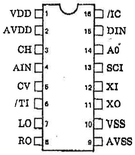
TOP VIEW
PIN DESCRIPTIONS
| Pin No. | Name | I/O | Function |
| 1 | VDD | - | Digital+5V power supply |
| 2 | AVDD | - | Analog+5V power supply |
| 3 | CH | O | Sample/hold capacitor terminal |
| 4 | AIN | I | Analog signal input |
| 5 | CV | O | Center voltage of A/D |
| 6 | /TI | I+ | Test terminal(without connection) |
| 7 | LO | O | L channel, analog out |
| 8 | RO | O | R channel, analog out |
| 9 | AVSS | - | Analog ground |
| 10 | VSS | - | Digital ground |
| 11 | XO | O | X'tal oscillator terminal(7.16 MHz typ.) |
| 12 | XI | I | |
| 13 | SCI | I | Bit clock for microprocessor interface |
| 14 | A0 | I | Word clock for microprocessor interface |
| 15 | DIN | I | Serial data for microprocessor interface |
| 16 | /IC | I+ | Initial clear terminal |
+; pulled up
BLOCK DIAGRAM
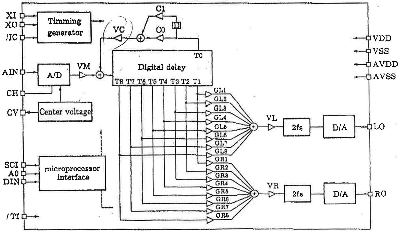
FUNCTION DESCRIPTION
As shown in the block diagram, analog signal input at AIN terminal are converted to 14 bit digital signal with the sampling frequency of 28.6 kHz using 14 bit floating type A/D converter, and then attenuated by the digital attenuator VM. Tap T0 output of digital delay passes through first order FIR type low pass filter and attenuated by VC. These signals are added before they are input to digital delay. Digital delay has nine output taps and tap positions can be switched by the registers T0 to T8. Outputs of eight taps from T1 to T8 are attenuated and added for each channel with the digital attenuator from GL1 to GL8 and GR1 to GR8 respectively, and attenuated by digital attenuator VL or VR to be input to two-times oversampling digital filter. Since this filter attenuates aliasing noise, it reduces the burden on external analog low pass-filter. Digital input to D/A converter shall be with doubled value, which is 47.1 kHz sampling rate.
MICROPROCESSOR INTERFACE
Digital attenuation value, delay time and FIR type low pass filter coefficients are all set by writing data into registers.
With A0 = 'L", 8 bit address data are sent synchronizing with SCI. At the rising edge of A0, register address is taken in. With A0 = 'H", 8 bit data are sent synchronizing with SCI, then register data are changed at the falling edge of A0.
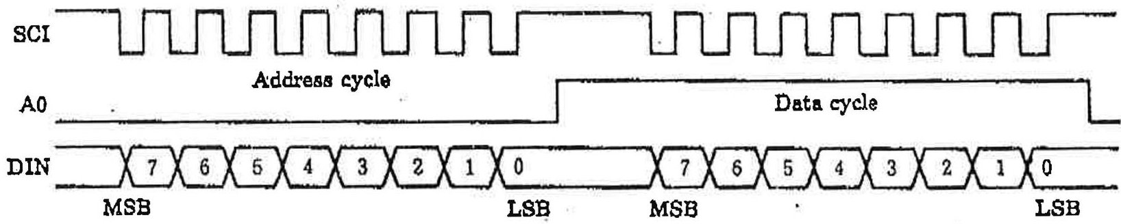
- At the time of initial clear, VM, VC, VL and VR registers are reset to 0. Other register values are not fixed.
REGISTER MAP
| Address(HEX) | Data | Function | Address(HEX) | Data | Function | ||
| 76543210 | 76543210 | ||||||
| 00 | xx | GL1 | Lch Tap attenuation value(bit 5; sign) | 10 | xx | VM | Attenuation value(bit 5; sign) |
| 01 | xx | GL2 | 11 | xx | VC | ||
| 02 | xx | GL3 | 12 | xx | VL | ||
| 03 | xx | GL4 | 18 | xx | VR | ||
| 04 | xx | GL5 | 14 | xx | C0 | FIR coefficient | |
| 05 | xx | GL6 | 15 | xx | C1 | ||
| 06 | xx | GL7 | 16 | xxx | T0 | Tap position | |
| 07 | xx | GL8 | 17 | xxx | T1 | ||
| 08 | xx | GR1 | Rch Tap attenuation value(bit 5; sign) | 18 | xxx | T2 | |
| 09 | xx | GR2 | 19 | xxx | T3 | ||
| 0A | xx | GR3 | 1A | xxx | T4 | ||
| 0B | xx | GR4 | 1B | xxx | T5 | ||
| 0C | xx | GR5 | 1C | xxx | T6 | ||
| 0D | xx | GR6 | 1D | xxx | T7 | ||
| 0E | xx | GR7 | 1E | xxx | T8 | ||
| 0F | xx | GR8 | |||||
Note 1) x; Don't Care
Note 2) Don't write to the other address
REGISTER DATA DESCRIPTION
(1) Attenuation value setting (GL1 to GL8, GR1 to GR8, VM, VC, VL, VR)
- Output polarity (bit 5)
When bit 5 - "1": Output signal is in phase with input signal.
When bit 5 = "0": Output signal is reversed phase with input signal.
- Attenuation value (bit 4-0)
| Level(dB) | Data | (HEX) | ||||
| 4 | 3 | 2 | 1 | 0 | ||
| 0 | 1 | 1 | 1 | 1 | 1F | |
| -2 | 1 | 1 | 1 | 1 | 1E | |
| -4 | 1 | 1 | 1 | 0 | 1D | |
| -6 | 1 | 1 | 1 | 0 | 1C | |
| -8 | 1 | 1 | 0 | 1 | 1B | |
| -10 | 1 | 1 | 0 | 1 | 1A | |
| -12 | 1 | 1 | 0 | 1 | 19 | |
| -14 | 1 | 1 | 0 | 0 | 18 | |
| -16 | 1 | 0 | 1 | 1 | 17 | |
| -18 | 1 | 0 | 1 | 1 | 16 | |
| -20 | 1 | 0 | 1 | 0 | 15 | |
| -22 | 1 | 0 | 1 | 0 | 14 | |
| -24 | 1 | 0 | 0 | 1 | 18 | |
| -26 | 1 | 0 | 0 | 1 | 12 | |
| -28 | 1 | 0 | 0 | 1 | 11 | |
| -30 | 1 | 0 | 0 | 0 | 10 | |
| Level(dB) | Data | |||
| 48210 | (HEX) | |||
| -82 | 01111 | 0F | ||
| -84 | 01110 | 0E | ||
| -38 | 01101 | 0D | ||
| -38 | 01100 | 0C | ||
| -40 | 01011 | 0B | ||
| -42 | 01010 | 0A | ||
| -44 | 01001 | 09 | ||
| -46 | 01000 | 08 | ||
| -48 | 00111 | 07 | ||
| -50 | 00110 | 06 | ||
| -52 | 00101 | 05 | ||
| -54 | 00100 | 04 | ||
| -56 | 00011 | 08 | ||
| -58 | 00010 | 02 | ||
| -60 | 00001 | 01 | ||
| -∞ | 00000 | 00 | ||
(2) Delay time setting (T0 to T8) (XI=7.16 MHz)
| Delay time(ms) | Data | ||||
| 4 | 3 | 2 | 10 | (HEX) | |
| 0.0 | 0 | 0 | 0 | 0 | 00 |
| 8.2 | 0 | 0 | 0 | 1 | 01 |
| 6.5 | 0 | 0 | 1 | 0 | 02 |
| 9.7 | 0 | 0 | 1 | 1 | 03 |
| 12.9 | 0 | 0 | 1 | 0 | 04 |
| 16.1 | 0 | 0 | 1 | 0 | 05 |
| 19.3 | 0 | 0 | 1 | 1 | 06 |
| 22.6 | 0 | 0 | 1 | 1 | 07 |
| 25.8 | 0 | 1 | 0 | 0 | 08 |
| 29.0 | 0 | 1 | 0 | 0 | 09 |
| 82.3 | 0 | 1 | 0 | 1 | 0A |
| 35.5 | 0 | 1 | 0 | 1 | 0B |
| 38.7 | 0 | 1 | 1 | 0 | 0C |
| 41.9 | 0 | 1 | 1 | 0 | 0D |
| 45.2 | 0 | 1 | 1 | 1 | 0E |
| 48.4 | 0 | 1 | 1 | 1 | 0F |
| Delay time(ms) | Data | ||||
| 4 | 3 | 2 | 10 | (HEX) | |
| 51.6 | 1 | 0 | 0 | 0 | 10 |
| 54.9 | 1 | 0 | 0 | 0 | 11 |
| 58.1 | 1 | 0 | 0 | 1 | 12 |
| 61.9 | 1 | 0 | 0 | 1 | 13 |
| 64.5 | 1 | 0 | 1 | 0 | 14 |
| 67.8 | 1 | 0 | 1 | 0 | 15 |
| 71.0 | 1 | 0 | 1 | 1 | 16 |
| 74.2 | 1 | 0 | 1 | 1 | 17 |
| 77.4 | 1 | 1 | 0 | 0 | 18 |
| 80.7 | 1 | 1 | 0 | 0 | 19 |
| 83.9 | 1 | 1 | 0 | 1 | 1A |
| 87.1 | 1 | 1 | 0 | 1 | 1B |
| 90.4 | 1 | 1 | 1 | 0 | 1C |
| 93.6 | 1 | 1 | 1 | 0 | 1D |
| 96.8 | 1 | 1 | 1 | 1 | 1E |
| 100.0 | 1 | 1 | 1 | 1 | 1F |
(3) FIR Low Pass Filter coefficient setting (C0, C1).
The lower 6 bits of coefficient register are used as the upper 6 bits of 12 bit 2's compliment data actually processed inside.
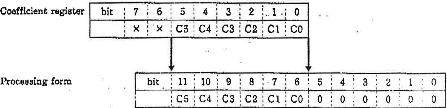
Decimal point
SYSTEM BLOCK DIAGRAM
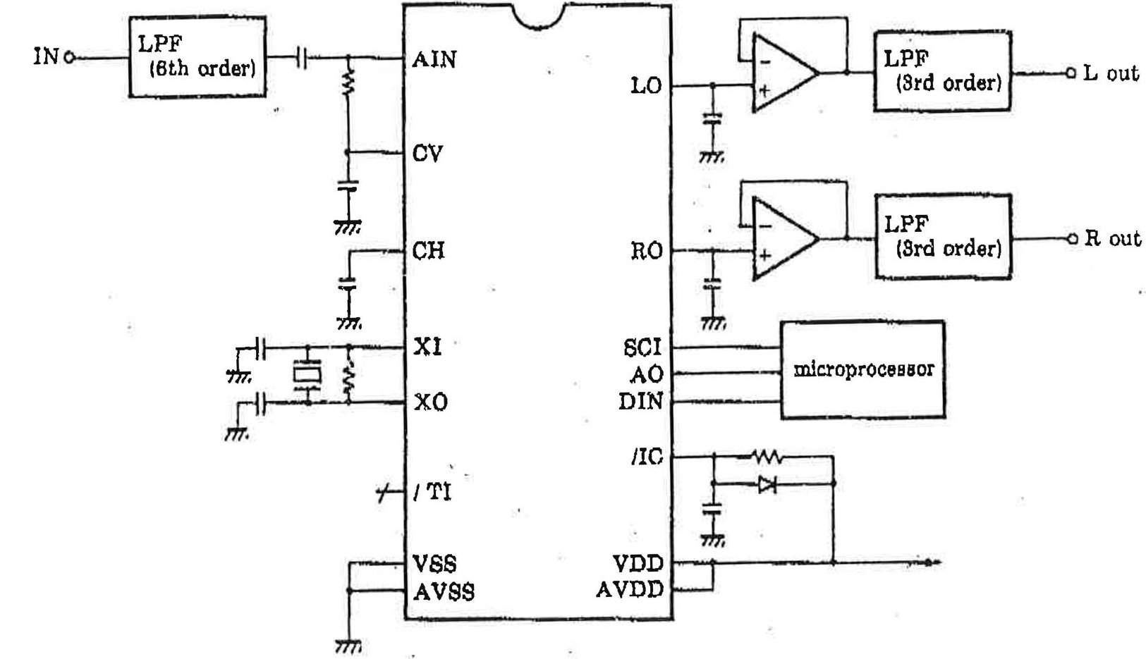
EXTERNAL DIMENSIONS
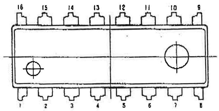
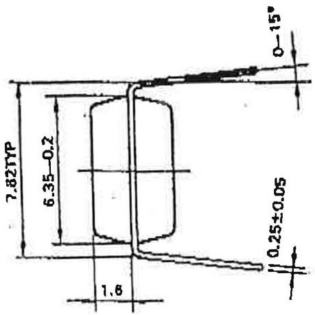
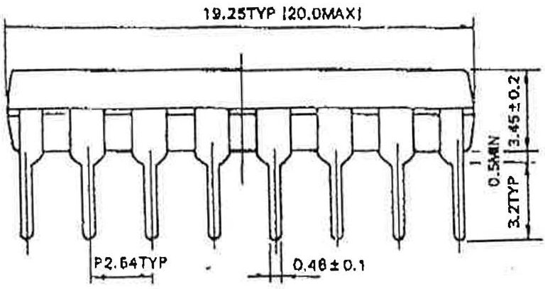
ELECTRICAL CHARACTERISTICS
- Absolute maximum ratings
| Parameter | Symbol | Rating | Unit |
| Supply voltage | VDD | -0.3~+7.0 | V |
| Operating temperature | Top | -20~+85 | °C |
| Storage temperature | Tatg | -50~+125 | °C |
- Recommended operating conditions
| Parameter | Symbol | Min. | Typ. | Max. | Unit |
| Supply voltage | VDD | 4.75 | 5.0 | 5.25 | V |
| Operating temperature | Top | 0 | 25 | 70 | °C |
- DC characteristics (Conditions: )
| Parameter | Symbol | Condition | Min. | Typ. | Max. | Unit | |
| Supply current | IDD | 50 | mA | ||||
| High-level input voltage(1) | VIH1 | 2.0 | V | *1 | |||
| Low-level input voltage(1) | VIL1 | 0.8 | V | *1 | |||
| High-level input voltage(2) | VIH2 | 4.0 | V | *2 | |||
| Low-level input voltage(2) | VIL2 | 0.8 | V | *2 | |||
| High-level output voltage | VOH | IOH=-0.4mA | 4.0 | V | |||
| Low-level output voltage | VOL | IOL=0.2mA | 0.4 | V | |||
| Input leakage current | IIL | VI=0~5V | -10 | 10 | µA | ||
| Input capacitance | C1 | 5.0 | 12.0 | pF | |||
| Output capacitance | CO | 10.0 | pF | ||||
Note 1: Applicable to the input terminals except XI Note 2: Applicable to XI terminal
- AC characteristics (Conditions:
| Parameter | Symbol | Min. | Typ. | Max. | Unit | |
| XI | Input frequency | fc | 8.6 | 7.16 | 8.6 | MHz |
| Duty | 40 | 50 | 60 | % | ||
| Rise time | TCR | 50 | ns | |||
| Fall time | TCF | 50 | ns | |||
| SCI | Input frequency | fs | fc/8 | MHz | ||
| On-off time | TS | 600 | ns | |||
| Rise time | TSR | 200 | ns | |||
| Fall time | TSF | 200 | ns | |||
- ANALOG characteristics (Conditions:
| Parameter | Symbol | Condition | Min. | Typ. | Max. | Unit |
| Analog input voltage | VIA | AIN terminal | 4.5 | Vp-p | ||
| Analog output voltage | VOA | LO, RO terminal | 4.5 | Vp-p | ||
| DC offset voltage | CV | 2.5 | V | |||
| Total harmonic distortion | THD | output voltage 0dB | 0.3 | 0.4 | % | |
| -10dB | 0.4 | 0.5 | % | |||
| -20dB | 0.4 | 0.5 | % | |||
| -30dB | 0.6 | 0.8 | % | |||
| S/N | S/N | S=0dB | 75 | 80 | dB |
Note) 0dB=1.5Vrms
REFERENCE CHARACTERISTICS 2 times oversampling filter
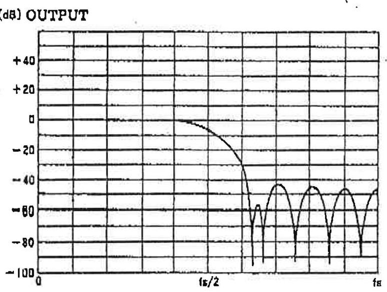
FREQUENCY
Output vs THD+NOISE
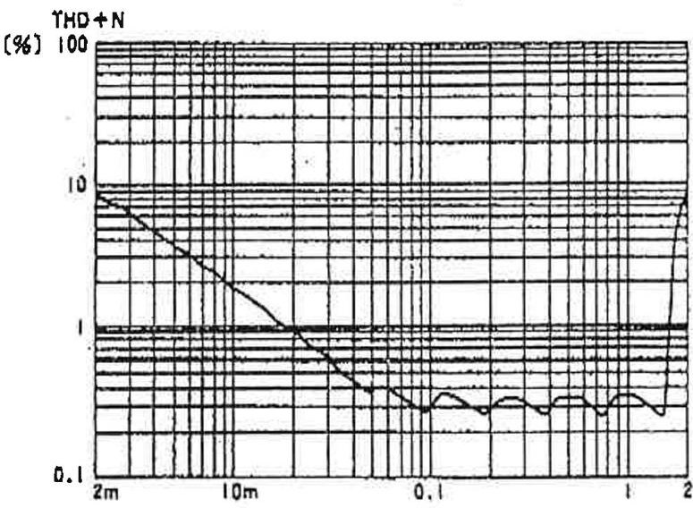
OUTPUT [Vrms]
The specifications of this product are subject to improvement changes without prior notice.
YAMAHA CORPORATION
Address inquiries to: Semi-conductor Sales Department
Head Office 203. Matsunokijima, Toyooka-mura, Iwata-gun, Shizuoka-ken, 438-01 Electronic Equipment business section Tel. 0639-62-4918 Fax. 0639-62-5054
Tokyo Office 8-4, Surugadal Kanda, Chlyoda-ku,
Tokyo, 101
Ryumeikan Bldg. 4F
Tel. 03-265-4481 Fax. 03-255-4488
Osaka Office 3-12-9, Minami Senba, Chuo-ku.
Osaka City, Osaka, 642
Shinsaibashi Plaza Bldg. 4F
Tel. 08-252-7980 Fax. 08-252-5615
U.S.A. YAMAHA Systems Technology. 652 Ridder Park Drive San Jose, CA95131 Tel. 408-437-3133 Fax. 408-437-8791
The following source code demonstrates how to program a Surround preset.
Function Write_Srnd_Reg writes the specified value to the YM7128 through the control chip register 18H. The sample code assumes that the control chip is located at address 38AH.
Function Write_Surround sends the 32 bytes of a suuround preset to the YM7128 using the bit-serial protocol. For each byte of the Surround preset, the register number (variable addr) is sent first , followed by the register value (variable data).
/*

    SURR.C

    Write a preset to the surround chip.

    Copyright 1992, Ad Lib Inc.

*/

unsigned control_io = 0x38a;        /* address of control chip section */

/* Write 'val' to the surround register in the control chip. */

static void _fastcall Write_Srnd_Reg (unsigned val)

{

    _asm {

        mov     dx, control_io

l10:

            in     al, dx

            test    al, 0c0h          ;status bits indicating chip is busy

            jnz     l10

            mov     ax, 18h          ;surround register number

            out     dx, al

            mov     ax, val

            inc     dx

            out     dx, al

    }

}
/* NOTE: When writing a byte to the control chip, it is very important that the transfer not be interrupted. Therefore, interrupts are disabled while the preset is being sent. */
void Write_Surround (unsigned char *preset);
{
unsigned addr, data, cmd;

int i, k;

_asm {

    pushf                        ;preserve the current interrupt state

    push     dx

    cli                        ;disable interrupts

    mov       dx, control_io

    mov       al, 0ffh            ;disable OPL3, enable control bank

    out       dx, al

}

/* Send the 31 array elements: */

for (i = 0; i < 31; i++) {

    cmd = 0;                        /* clock LOW, A0 LOW */

    addr = i;

    for (k = 7; k >= 0; k--) {

        cmd &= ~2;                    /* clock LOW */

        Write_Srnd_Reg (cmd);

        cmd = (cmd & ~1) | ((addr >> k) & 1);

        Write_Srnd_Reg (cmd);

        cmd |= 2;                    /* clock HIGH */

        Write_Srnd_Reg (cmd);

    }

    cmd |= 4;                        /* Set A0 to 1 */

    Write_Srnd_Reg (cmd);

    data = preset [i];

    for (k = 7; k >= 0; k--) {

        cmd &= ~2;                    /* clock LOW */

        Write_Srnd_Reg (cmd);

        cmd = (cmd & ~1) | ((data >> k) & 1);

        Write_Srnd_Reg (cmd);

        cmd |= 2;                    /* clock HIGH */

        Write_Srnd_Reg (cmd);

    }

    cmd &= ~4;                        /* Set A0 to 0 */

    Write_Srnd_Reg (cmd);

}

_asm {

    mov       dx, control_io
120:
    in       al, dx

    test     al, 0c0h            ;status bits indicating chip is busy

    jnz      l20

    mov       al, 0feh            ;enable OPL3, disable control bank

    out      dx, al

    pop      dx

    popf        ;restore previous interrupt state

}
}
Ad Lib Gold © Ad Lib Inc.1992 Confidential Mon, Mar 23,1992
PIN OUT FOR JOYSTICK-MIDI CONNECTOR OF THE Ad Lib GOLD CARD
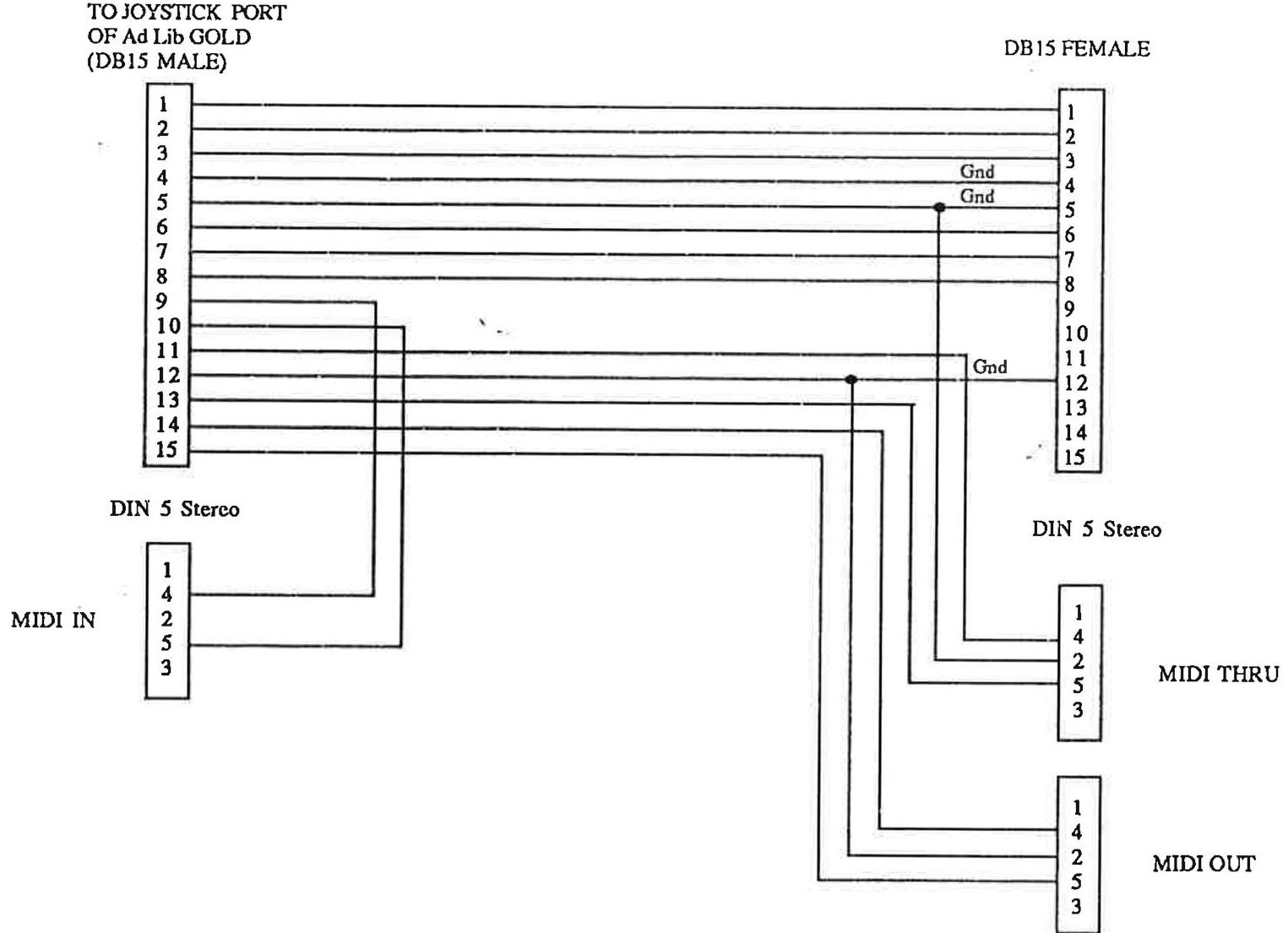
Appendix D: List of Installed Files
Every file installed by the toolkit: drivers, TSRs, applications, batch files and resources.
Appendix D: List of Installed Files
The Ad Lib Gold Developer Toolkit software included in the diskettes contains, when decompressed and installed, several files related to the utilization of the Gold card: drivers, application programs, music, sounds, and other various files. These files are:
README.TXT
This file is not compressed on the diskette. It contains information on the latest program updates, if there are any, and any other pertinent information.
CTRLDRV.EXE
This file is not compressed on the diskette. It contains the Ad Lib Gold Control chip driver. This low level driver is used by other programs, such as the Setup program, to implement: DMA channel & interrupt number select; sampling source select; sampling gain and input filter; microphone input gain; sampling output filtering and volume & tone control; mixing control; card localization setup and ID code reading; saving registers in non volatile memory.
SETUP.EXE
This file is not compressed on the diskette. It contains the Installation and Configuration program. This program enables you to install the drivers and all associated programs, and to configure your Ad Lib Gold card.
Drivers and TSRs
Are located in the "DRIVERS" subdirectory.
FMDRV.EXE
This file contains the FM driver. This low level driver implements: preset change; note on; note off; pitch bend; volume and stereo positioning.
WAVEDRV.EXE
This file contains the Sampling driver. This low level driver implements: recording and playback of samples by DMA and interrupt.
TIMERDRV.EXE
MIDIDRV.EXE
This file contains the Timer driver. This low level driver implements: the five timers of the Yamaha Magic Chip Set.
This file contains the MIDI driver. This low level driver implements: MIDI In and Out serial port control.
RL2DRV.EXE
This file contains the ROL2 driver. This low level TSR driver implements: playback of the .RL2 music files and user control commands.
AppendIx D
List of Installed Files
MIXER.EXE
This file contains the Mixer Panel TSR. This memory resident application allows for the control of the programmable volume and tone control, mixer settings, surround features, and setting of activation and volume keys.
Application Programs (Executables)
TESTGOLD.EXE
This file contains the Ad Lib Gold Test Program. This program enables you to verify that the Gold card is functioning properly in all of its different components.
JUKEG.EXE
This file contains the executable code of Juke Box Gold Music Playback Program.
ED.EXE
This file contains the executable code of Instrument Maker Gold.
SAMPL.EXE
This file contains the executable code of Sample Maker Program.
SURR.EXE
This file contains the executable code of Juke Box Gold with the Surround Sound Editor.
PLAYRL2.EXE
This file contains the executable code of ROL2 Playback utility.
PLAYDIGI.EXE
This file contains the executable code of Digitized Sound Playback utility.
Batch Files
TEST.BAT
This file contains the DOS command sequence which loads the necessary drivers and calls the Ad Lib Gold Test Program.
JUKEGOLD.BAT
This file contains the DOS command sequence which loads the necessary drivers and calls the Juke Box Gold Music Playback Program.
INSGOLD.BAT
This file contains the DOS command sequence which loads Instrument Maker Gold.
SURROUND.BAT
This file contains the DOS command sequence which loads the necessary drivers and calls the Juke Box Gold Music Playback Program with the Surround Sound Editor.
DRIVERS.BAT
This file contains the DOS command sequence which loads all Ad Lib Gold drivers.
Other Files
* *.RL2
The ".RL2" files contain the pieces of music that will be played with the Juke Box Gold.
* *.SMP
The ".SMP" files contain the PCM digitized sounds. TESTGLD1.SMP is the sound file that will be used by the Test Program.
SAMPLBNK.EQU
This file contains a translation table of digitized instrument sound names, which is used by the ROL2 Playback driver.
OPL3.BNK
This file contains the FM synthesized instrument sounds compatible with the OPL3 FM synthesis chip.
ED.RSR
This file contains the resources required by Instrument Maker Gold.
SAMPL.RSR
This file contains the resources required by Sample Maker Program.
Files Created by Programs
JUKEGOLD.DAT
This file is created the first time you make a selection of songs in the Juke Box Gold program, permitting not to lose your selection even after rebooting the computer.
TESTGLD1.SMP
This file is created by the Test Program when you test Sampling and Playback.
SAMPLES.BNK
This bank file is created by the Sample Maker Program the first time you save a digitized sound in the ADPCM format.
Appendix E — Program Disks (as shipped)
The Ad Lib Gold Program Disks, version 1.00 (1992) are the end-user software that shipped with the card. This appendix preserves them exactly as distributed: the authentic 720 KB floppy images, every file byte-for-byte in its original DOS (CP437 / CRLF) form, and a UTF-8 rendering of each text file.
The expanded result of running the installer is documented separately in
Appendix F — Software (as installed); the
compression format of the GOLD*.CMP archive is reverse-engineered in
Appendix H — the "Ad Lib Comp." format.
Release timeline
The Ad Lib Gold software was released across 1992–93 — all preserved in this archive. The dates below are the newest confirmed file timestamp in each release's own files (FAT directory entries, or archive metadata for the Windows drivers) — the most reliable evidence of when each master was cut. Because the lineages are versioned independently (the SDK Developer Toolkit, the retail Program Disks, and the Windows driver package), the version numbers do not track the dates:
| Date | Release | Version | Where |
|---|---|---|---|
| Apr 1992 | Beta software | v0.91b | Appendix G |
| Apr 1992 | Developer Toolkit | v1.01 | Appendix G (this manual) |
| Oct 1992 | Program Disks | v1.00 | this appendix |
| Oct 1992 | Windows Mixer & Drivers | v0.9 | below |
| Dec 1992 | Windows Mixer & Drivers | v0.9b | below |
| Jul 1993 | Windows Mixer & Drivers | v1.2 (latest) | below |
Dating basis — the newest genuine file in each set, excluding two
1994-03-30 archival re-master stamps and disk-ripper tags. Evidence: Beta
SETUP.EXE 2 Apr, payload GOLD.CMP 9 Apr 1992 (its README is dated 31 Mar
1992); Developer Toolkit files 30 Mar – 2 Apr 1992 — the SDTK.DOC
"Thu, Jul 8 1993" page footer is a Microsoft Word auto-date field, not the
authoring date; Program Disks core install GOLD1/2/3.CMP 30 Sep – 1 Oct
1992, but this archived master is a later composite re-cut that also bundles the
1993 GSS Windows drivers (GSS.DRV 10 Mar 1993, byte-identical to v1.2) and a
14 Nov 1993 G2S.EXE; Windows v0.9 to 27 Oct 1992, v0.9b to 4 Dec 1992, v1.2
binaries Mar 1993 / README 13 Jul 1993. The "Ad Lib Comp." container stores only
a name and compressed size per file — no timestamps — so the compressed payloads
add no further dates.
Provenance & integrity
The three images are the authentic v1.00 release preserved by the Internet
Archive (adlib-gold-bundle),
cross-checked against the VGMPF copy. Each is a genuine 720 KB double-density
floppy. Before inclusion every image was:
- boot-sector verified — a benign, stock loader; the OEM signature is
ALF 3.0("Copyright 1987 ALF Products Inc."), the disk-duplication hardware Ad Lib used to master retail floppies. No boot-sector virus code is present (the legitimate "Non-System disk" loader occupies the standard offset, and no known signature — Stoned/Form/Michelangelo/… — appears). - malware-scanned — Microsoft Defender reported no threats.
Disk images (mountable in DOSBox / any emulator):
Disk 1 — installer & control driver
| Size | File | Notes |
|---|---|---|
| 470 | SETUP.BAT (md) | runs CTRLDRV then SETUPGLD |
| 291 776 | SETUPGLD.EXE | the installer (expands GOLD*.CMP) |
| 12 048 | CTRLDRV.EXE | control-chip TSR / card detection |
| 417 508 | GOLD1.CMP | first part of the spanned install archive |
| 1 113 | README.TXT (md) | v1.00 install notes |
Disk 2 — archive part 2, Sound Blaster emulator, Windows MIDI
| Size | File | Notes |
|---|---|---|
| 603 174 | GOLD2.CMP | second part of the spanned archive |
| 19 120 | G2S/G2S.EXE | Sound Blaster emulator — a V86-mode TSR (≈352 bytes resident) that traps SB I/O and remaps it to the Gold hardware (~50% of SB apps; also emulates a DAC on LPT1) |
| 3 064 | G2S/G2S.DOC | its documentation |
| 37 742 | WIN_MIDI/MIDIMAP.CFG | Windows MIDI mapper config |
| 112 | WIN_MIDI/README.TXT |
Disk 3 — archive part 3, Windows 3.1 drivers
| Size | File | Notes |
|---|---|---|
| 545 106 | GOLD3.CMP | third part of the spanned archive |
| 77 312 | WINDRV/MIXERGLD.EXE | Windows mixer applet |
| 25 600 | WINDRV/OPL3.CPL | OPL3 control-panel applet |
| 20 704 | WINDRV/GSSOPL3.DRV | Windows OPL3 driver |
| 17 984 | WINDRV/GSS.DRV | Windows Gold Sound Standard driver |
| 13 946 | WINDRV/OPL3.HLP | help file |
| 5 854 | WINDRV/VGSS.386 | Windows 386 virtual device |
| 238 | WINDRV/OEMSETUP.INF | Windows driver install info |
| 8 587 | WINDRV/README.TXT | Windows driver notes |
GOLD1.CMP+GOLD2.CMP+GOLD3.CMPtogether form one spanned "Ad Lib Comp." archive — a proprietary LZ+Huffman container expanded bySETUPGLD. Its format and the recovery of its 133-file payload are documented in Appendix H; the payload itself is browsable in Appendix F.
Windows 3.1 Mixer & Drivers
The Windows drivers shipped separately from the DOS software (via the Ad Lib
BBS) and went through three revisions — the newest of which, v1.2 (July
1993), is the last dated Ad Lib Gold artifact of any kind. The early releases
used a single combined driver (SFGOLD.DRV + VGOLD.386); by v1.2 this had been
split and renamed into two GSS drivers. The Windows mixer applet MIXERGLD.EXE
is unchanged across all three. All are preserved here and malware-scanned clean.
v1.2 (July 1993) — the latest
Two Windows drivers (the Yamaha GSS MIDI Synth and the GSS Wave/MIDI/Aux
driver), the mixer applet, and a MIDI-mapper configuration. These driver binaries
are byte-identical to the WINDRV set on Program Disk 3, so v1.2 is essentially a
re-release with updated documentation.
| Size | File | Notes |
|---|---|---|
| 8 480 | README.TXT (rendered) | v1.2 install guide (July 1993) |
| 17 984 | GSS.DRV | Gold Sound Standard Wave/MIDI/Aux driver |
| 20 704 | GSSOPL3.DRV | GSS MIDI Synth (OPL3) driver |
| 77 312 | MIXERGLD.EXE | Windows Gold mixer applet |
| 25 600 | OPL3.CPL | Control-Panel applet |
| 13 946 | OPL3.HLP | help file |
| 5 854 | VGSS.386 | 386 virtual device |
| 238 | OEMSETUP.INF | Windows driver install info |
| 37 742 | MIDIMAP.CFG | MIDI-mapper configuration |
| 19 120 | G2S.EXE (.DOC) | the Sound Blaster emulator (bundled) |
Earlier releases (pre-GSS architecture)
Two pre-release Windows driver disks survive, using the older combined
SFGOLD.DRV + VGOLD.386 design:
| Version | Date | Contents | Notes |
|---|---|---|---|
| v0.9 | Oct 1992 | SFGOLD.DRV, VGOLD.386, MIXERGLD.EXE, MIDIMAP.CFG, OEMSETUP.INF (README) | first Windows driver |
| v0.9b | Dec 1992 | same set, updated (README) | adds [sfgold.drv] system.ini tuning options |
Browse the raw files: v0.9 · v0.9b · v1.2.
Appendix F — Software (as installed)
Running SETUPGLD on the Program Disks expands
the spanned GOLD*.CMP archive into a \GOLD directory of 133 files: the
DOS drivers, the end-user applications, a large sample library and a set of demo
songs. This appendix presents that complete installed tree.
The files here were not obtained by running the 1992 installer (it aborts
with "Gold Card not found" on any machine without the hardware, and its
decompressor is entangled with the C++ runtime). Instead the "Ad Lib Comp."
container format and its LZ+Huffman codec were reverse-engineered from
SETUPGLD.EXE and re-implemented — see
Appendix H. Correctness is proven: the recovered
CTRLDRV.EXE is byte-for-byte identical (matching MD5) to the copy that ships
uncompressed on Program Disk 1, and every recovered executable is a valid
MZ image. The tree was malware-scanned clean.
Browse the decoded files under
disks/program-disks-v1.00/installed/.
\GOLD\DRIVERS — DOS device drivers
The loadable driver set documented in Chapter 5.
| Size | Driver | Role |
|---|---|---|
| 12 048 | CTRLDRV.EXE | Control chip — mixer, card setup, IRQ/DMA (Ch. 7.1) |
| 11 648 | FMDRV.EXE | FM synthesis (OPL3 / YMF262) |
| 22 416 | WAVEDRV.EXE | Digital audio (MMA / YMZ263) |
| 6 508 | MIDIDRV.EXE | MIDI I/O |
| 10 050 | TIMERDRV.EXE | Timer services |
| 32 835 | SYNCDRV.EXE | Synchronisation |
| 51 553 | RL2DRV.EXE | .RL2 music playback |
| 40 605 | ALARMDRV.EXE | Alarm / scheduling |
\GOLD — applications
| Size | Program | Role |
|---|---|---|
| 278 861 | TESTGOLD.EXE | card test / diagnostics (Ch. 4) |
| 286 385 | VPAD.EXE | VoicePad |
| 285 704 | SNDTRACK.EXE | SoundTracker |
| 179 518 | JUKEG.EXE | Jukebox |
| 73 532 | ANIMGLD.EXE | animation player |
| 44 022 | PLAYDIGI.EXE | digital-audio player |
| 23 770 | MIXER.EXE | mixer panel |
| 15 212 | PLAYRL2.EXE | .RL2 player |
Plus batch launchers (SETUP.BAT, TEST.BAT, JUKEGOLD.BAT,
STRACKED.BAT, VOICEPAD.BAT, PLAYANIM.BAT, DRIVERS.BAT, STRKDRV.BAT),
instrument banks OPL3.BNK / SAMPLES.BNK, a sync demo SYNCDEMO.SNC, and the
installed README.TXT
(md).
\GOLD — demo songs (.RL2)
Fourteen .RL2 sequences ship as demos: BUILDING, CAVE, FLIGHT,
HIGHWAY2, INDUSTRY, KRAKEN, LORDS, LUTECONC, MACHINE, MIRRORS,
NEWERA, TOCCATA2, ULTIMATE, WALKPARK.
\GOLD\SMP — sample library
90 .SMP sample files — the percussion and instrument library used by the
tools (bass/snare drums, cymbals, hi-hats, congas, cowbells, claves, bells,
brushes, handclaps, and the $TEXT* speech samples). See the
full listing.
Version history (v0.91b beta → v1.00)
Because the codec is now decodable, the beta software (v0.91b, 31 March 1992) — preserved as floppy images in Appendix G — can be expanded too and diffed against the v1.00 release (23 April 1992, three weeks later). The changes:
- Sample library reorganised. In the beta the ~85
.SMPfiles sat loose in\GOLD; v1.00 moves them into the new\GOLD\SMPsub-directory. This accounts for most of the apparent file churn — the samples themselves are unchanged. - Demo songs renamed — the beta's
*GLD/*GDsuffixes were dropped:BUILDGLD→BUILDING,CAVEGLD→CAVE,ERAGLD→NEWERA,INDUSGLD→INDUSTRY,KRAKENGD→KRAKEN,MACHIGLD→MACHINE,MIRRORGD→MIRRORS,ULTIMGLD→ULTIMATE,WALKGLD→WALKPARK,LUTECON→LUTECONC. The beta'sFUGUE2/PRELUDE2were dropped;TOCCATA2,HIGHWAY2,FLIGHTandLORDSwere added. SAMPLBNK.EQUremoved — confirmed verbatim by the v1.00README: "Due to changes in the .RL2 file format, file SAMPLBNK.EQU is no longer necessary and has been removed."- Animation player restructured — the beta's single
PLAYANIM.EXEbecame aPLAYANIM.BATlauncher driving a newANIMGLD.EXE. - Every driver and application was recompiled (all compressed sizes differ);
most notably
ALARMDRV.EXEandPLAYRL2.EXEroughly halved in size. - Batch reshuffle —
SYNCDRV.BATdropped,STRKDRV.BATadded, andSETUP.BATfolded into the payload (it now auto-callsCTRLDRV.EXE, per the v1.00README).
The beta README also records user-facing changes settling in just before
release: the MIXER/RL2DRV hotkeys became redefinable from SETUP, and the
mixer's F4 key was repurposed to save the configuration permanently to
EEPROM. Developer-facing addenda continued into v1.01 — the
Release Notes add the RL2DRV driver-ordering requirement,
the SAMPL.EXE library-conflict warning, and the interrupt-disable discipline
for hardware access.
Appendix G — Developer SDK
Beyond the end-user Program Disks, Ad Lib shipped a Developer Toolkit — the C/assembly source of the DOS drivers documented in Chapter 5 and Chapter 7, with buildable examples. This appendix preserves it.
Editions
Three distinct developer/pre-release lineages exist; all are preserved here as authentic floppy images:
| Edition | Disks | Contents |
|---|---|---|
| Developer Toolkit v1.01 | 3 × 720 KB | installer floppies that expand to the SDK source below |
| Beta Software v0.91b | 3 × 720 KB | pre-release drivers/software |
| (Program Disks v1.00) | — | the end-user release, in Appendix E |
Toolkit v1.01 images:
Disk 1 ·
Disk 2 ·
Disk 3.
Beta v0.91b images are under
disks/beta-v0.91b/images/.
Beta v0.91b disk contents
The beta (31 March 1992) is an installer set, structured like the release: a
SETUP.EXE plus a spanned GOLD.CMP archive that expands to a 130-file \GOLD
tree (three weeks before v1.00 — the differences are catalogued in the
v0.91b → v1.00 changelog).
That payload has been decoded and is browsable at
disks/beta-v0.91b/installed/ — note the samples
sit loose in \GOLD (they were only moved into \GOLD\SMP for the v1.00 release)
and SAMPLBNK.EQU is still present (dropped in v1.00). The as-shipped files:
| Size | File | Notes |
|---|---|---|
| 292 536 | SETUP.EXE | beta installer |
| 11 962 | CTRLDRV.EXE | control-chip TSR |
| 1 165 | README.TXT (rendered) | beta notes / hotkey changes |
| 412 698 / 714 950 / 464 053 | GOLD.CMP (disk 1 / 2 / 3) | spanned "Ad Lib Comp." payload (format) |
SDK source (installed toolkit)
The toolkit expands to the driver source in
disks/developer-toolkit-v1.01/installed/.
Each source file is preserved in its original DOS encoding, with a UTF-8
rendering alongside.
| Module | Source | Header | Documents |
|---|---|---|---|
| Control chip | CONTROL.C | CONTROL.H | Ch. 7.1 mixer/setup |
| FM synthesis | FM.ASM | FM.H | Ch. 7.2 YMF262 |
| Digital audio | WAVE.C | WAVE.H | Ch. 7.3 MMA |
| MIDI | MIDI.C | MIDI.H | Ch. 5 |
| Timers | TIMER.C | TIMER.H | Ch. 7 timers |
| Interrupts | INTERR.C | INTERR.H | |
| Get/Set | SET_GET.C | SET_GET.H |
Shared: GLOBAL.H,
DMA.H,
MYMACRO.INC,
MODEL2.MAC,
MAKEFILE.
Pre-built library: DRIVERS.LIB. Editor: ED.EXE. Sampler: SAMPL.EXE.
The toolkit manual itself, SDTK.DOC, is a Microsoft Word-for-DOS binary. The
DOS-era .DOC format was never officially published, so it is preserved
byte-for-byte and rendered
to faithful UTF-8 Markdown — the format decoded directly (CP437 body, 0x07 table
cells, 0x13/14/15 Word fields), with all 51 tables reconstructed and every text
byte preserved:
SDTK manual (rendered).
Example programs (SAMPLE/)
Buildable examples exercising each subsystem:
FMS.C (FM),
MIDIS.C (MIDI),
PLAYBACK.C /
RECORD.C (digital audio),
TIMERS.C (timers),
each with its MAKEFILE and .LNK.
Appendix H — The "Ad Lib Comp." format
The Ad Lib Gold software ships compressed in a proprietary container,
GOLD*.CMP, expanded at install time by SETUPGLD.EXE. Because the installer
gates on the physical card ("Gold Card not found") and its decompressor is
bound up with the C++ runtime, recovering the installed
files meant reverse-engineering the format from the
16-bit executable. This appendix documents both the container and its codec.
The container
Every stream begins with the ASCII magic Ad Lib Comp. followed by 1A 00.
After the 14-byte header comes a marker stream:
| Marker | Meaning |
|---|---|
0xFB + name\0 | push directory (leading \ = absolute, else a sub-directory) |
0xFD | pop directory |
0xFF + name\0 + u32 size + data | file (little-endian compressed size, then that many bytes) |
0xFC + disk# | disk boundary — the archive spans GOLD1/2/3.CMP |
0xFE | end of archive |
Concatenating the three spanned parts and walking this stream recovers the full
directory tree — 133 files across \GOLD, \GOLD\DRIVERS and \GOLD\SMP.
Note the per-file header stores only the compressed size; the decoder runs
until its input is exhausted.
The codec
Each file's payload is a bespoke LZ77 + static-Huffman stream (conceptually DEFLATE-like, but Ad Lib's own bit-format), decoded LSB-first:
-
3-byte prologue:
mode,offset-bits(4–6), and a bit-buffer seed. -
Literal/length alphabet: a 16-entry Huffman tree selects a category; a base value plus a few extra bits give the symbol. Values
< 0x100are literal bytes;≥ 0x100are match lengths (length = value − 0xFE, minimum 2). The category bases and extra-bit widths are:category 0–7 8 9 10 11 12 13 14 15 base 0…7 8 10 14 22 38 70 134 262 extra bits 0 1 2 3 4 5 6 7 8 -
Offsets: a 64-entry Huffman position tree, with a length-dependent number of direct bits appended (2 bits when the match length is 2, otherwise the header's
offset-bits). -
Window: an 8 KB sliding window, flushed 4 KB at a time; an end symbol (
0x306) terminates. In mode 0 — used by all 133 files — the Huffman tables are the fixed set above rather than being transmitted.
How it was recovered
Static analysis with capstone located the decode routines in SETUPGLD.EXE
(the main LZ loop, decode_char, decode_position, the getbits bit-reader and
make_table) and mapped the decoder's state structure. The tables make_table
reads are addressed cs:-relative — and pinning that code-segment base was
the whole puzzle: the constants only make sense at the correct segment.
The winning trick was a Kraft-equality test. A valid canonical-Huffman
code-length table satisfies Σ 2^(16−len) = 65536 exactly. Scanning every
plausible segment for a region where both the 16- and 64-entry length tables
pass Kraft yielded exactly one candidate (segment 0x35DD) — with textbook
length tables ([3,2,3,3,4,4,4,5,5,5,5,6,6,6,7,7], …). With the real tables in
hand, the genuine decode routines were driven over them (via a unicorn CPU
emulation, sidestepping the C++ init) and validated against the oracle:
CTRLDRV.EXE, which ships uncompressed on Disk 1, decoded byte-for-byte
identically. All 133 files then decoded in seconds.
This is a preservation/interoperability reverse-engineering of a 1992 format whose author released the surrounding toolkit as freeware; it exists only to recover the archived software documented in Appendix F.
program-disks-v1.00/disk1/README.TXT
UTF-8 rendering of a DOS-encoded (CP437 / CRLF) file. Byte-for-byte original:
README.TXT.
Ad Lib Gold Software Version 1.00                            April 23, 1992
***************************************************************************

To install the software, ensure that the installation diskette is in
the current drive, then type:

        setup

***************************************************************************

The following procedures have been modified and are different from their
description in the User Guide.

        - Due to changes int the .RL2 file format, file SAMPLBNK.EQU
          is no longer necessary and has been removed.

	- SETUP.BAT automatically call CTRLDRV.EXE and so does not have to
          be called separately, as described in the User Guide on page 12.

***************************************************************************

The Windows drivers for the Gold 1000 are on the Program Disk No. 3 into the
WINDRV directory.  You will find the MIDI configuration file on the Program
Disk No. 2 into the WIN_MIDI directory. The Gold to SoundBlaster simulator is
also on the Program Disk No. 2 but on the G2S directory.
program-disks-v1.00/disk1/SETUP.BAT
UTF-8 rendering of a DOS-encoded (CP437 / CRLF) file. Byte-for-byte original:
SETUP.BAT.
echo off
if exist setupgld.exe goto ok
goto err
:ok
if "%1" == "/R" goto reset
if "%1" == "/r" goto reset
@ctrldrv
@setupgld /install
goto end
:reset
@setupgld /R
goto end
:err
echo Ad Lib Gold Installation Program.
echo *********************************
echo .
echo The drive containing Program Disk 1 should be the current drive.
echo For example, to install the program from drive "A:" type:
echo    A:
echo    SETUP
goto end
:end
echo on
program-disks-v1.00/disk2/G2S/G2S.DOC
UTF-8 rendering of a DOS-encoded (CP437 / CRLF) file. Byte-for-byte original:
G2S.DOC.
SOUND BLASTER COMPATIBILITY

In this package we include a new driver.  This driver will let you emulate the
Sound Blaster product from your Ad Lib Gold 1000.  This give you the power of
all the Ad Lib, Sound Blaster and all the compagnies compatible with those.

You will find this driver on the diskette name "Program Disk No. 2" in the
G2S directory.  The name of this driver is G2S.EXE.

Instalation:  To install this driver you just have to copy it to your Ad Lib
Gold directory.  Type; copy a: (or b:) G2S.* c:\ (or the drive where is the Gold
directory) Gold (or the name you did give to the Ad Lib Gold directory) ENTER.
Then follow the instruction bellow (or in the G2S.DOC file, this file).  A list
of the compatible games and updates of the driver will be on the Ad Lib
Multimedia BBS at (418)656-0351.

Ad Lib Multimedia.


┌──────────────────┬─────────────────────────────────────────────────────────
│ WHAT IS IT FOR ? │
└──────────────────┘    G2S tries to simulate the Sound Blaster card on
                        the Ad Lib Gold 1000. It's still in a development
                        stage, but it should work with around 50% of the
                        Sound Blaster applications. G2S simulates a DAC on
                        LPT1 as well (this may work even if the SB simulation
                        does not).

                        When run, G2S installs itself into XMS, leaving
                        just 352 bytes in DOS memory. G2S switches CPU
                        into V86 mode, traps any I/O at SB addresses and
                        converts them into corresponding I/O to GOLD
                        (easier said than done :-) ). Run it before
                        an SB application, G2S will do the rest. Just
                        don't try to run any Ad Lib Gold application
                        with G2S installed (reset your PC first) !

                        G2S requires the following:

                           - i386 compatible CPU.
                           - Ad Lib Gold configured for DMA 1 and IRQ 5.
                           - HIMEM.SYS or compatible XMS manager installed.
                           - _NO_ V86 mode software (EMM386, ...).

┌─────────────────┬──────────────────────────────────────────────────────────
│ ALPHA TESTING ! │
└─────────────────┘     I have decided to release this version to test
                        the demand for such a software. Please let me know
                        if you find the simulator useful.

                        I have tested several SB applications with G2S.
                        Several of them worked (DUNE, DUNE II, GODS,
                        GOBLIIINS, GOBLIIINS 2, MODPLAY, DMP, TETRAMED,
                        several demos etc.), while the others did not
                        (DRAGON'S LAIR, several more demos etc.). You may
                        find out that the DAC-on-LPT1 works better than
                        the simulated SB.
program-disks-v1.00/disk2/WIN_MIDI/README.TXT
UTF-8 rendering of a DOS-encoded (CP437 / CRLF) file. Byte-for-byte original:
README.TXT.
If you wich to have General MIDI setting for your Gold Card, copy this file
in the \windows\system directory.
program-disks-v1.00/disk3/WINDRV/OEMSETUP.INF
UTF-8 rendering of a DOS-encoded (CP437 / CRLF) file. Byte-for-byte original:
OEMSETUP.INF.
[disks]
1=.\,"Yamaha GSS Wave/Midi/Aux"

[Installable.Drivers]
gss = 1:gss.drv,"Wave,Midi,Aux", "Yamaha GSS Wave/Midi/Aux",1:vgss.386,,
gssopl3 = 1:gssopl3.drv,"Midi", "Yamaha GSS Midi Synth",,,

[gssopl3]
1:opl3.cpl
1:opl3.hlp
program-disks-v1.00/disk3/WINDRV/README.TXT
UTF-8 rendering of a DOS-encoded (CP437 / CRLF) file. Byte-for-byte original:
README.TXT.
* Ad Lib Gold Mixer and Windows Drivers, Version 1.2           (July 1993)
*****************************************************

    This document will instruct you on how to install the Ad Lib Gold
    Mixer and drivers for Windows 3.1 (found on the diskette entitled
    "Program Disk No. 3" in the WINDRV directory).


* Contents of the diskette
***************************

    There are 2 separate  Ad Lib Gold Windows Drivers. Each of the
    driver covers separate aspects of the Ad Lib Gold multimedia
    capabilities.

    The first driver, called the Yamaha GSS Midi Synth, is used by
    Windows to play back MIDI data using the internal synthesizer of
    the Ad Lib Gold Card (which uses an FM synthesizer). Once loaded,
    this driver will install a special configuration applet in the
    Control Panel.

    The second driver, called the Yamaha GSS Wave/Midi/Aux driver,
    covers all other multimedia capabilities of the Gold Card.  The
    Wave section enables digitized sound playback under Windows for all
    applications that use wave files (such as the Sound Recorder,
    StudioSonic 8 or the System Sounds).  The MIDI section is used to
    play back and record MIDI data through the Ad Lib Gold MIDI Port.
    Finally, the AUX section of the driver provides the applications
    with a mechanism to dynamically control the various mixer controls
    (volume, bass, treble) of the Gold Card.


* Ad Lib Gold Mixer for Windows
*******************************

    You can use this application to control the Ad Lib Gold card's
    programmable mixer.


* Configuration file for Windows MIDI Mapper
********************************************
    (found on the diskette entitled "Program Disk No. 2" in
     the WIN_MIDI directory).

    This configuration file can be used to replace your current MIDI
    mapper configuration with setups that make optimal use of the Gold
    Card's capabilities.


* Installing the Software
*************************

* Configuring the Gold Card

    In order for the drivers to function properly, an interrupt and at
    least one DMA channel must have been allocated to the Gold card.
    To allocate an interrupt and DMA channel, use the Gold Setup
    program, supplied on the Gold program disks, under DOS.

    You should take note of the interrupt line (IRQ) and DMA channel
    that you've selected.  This information will be needed when
    installing the Yamaha GSS Wave/Midi/Aux driver.

* Installing the drivers

    To install the drivers, you will need to activate the "Drivers"
    applet found in the "Control Panel" (you'll find this last one in
    the "Main" program group).

    This is where you will add the new Ad Lib Gold Windows Drivers:

    Click on the "Add..." button.  You will be shown a list of the
    available drivers that can be added to Windows.  From this list,
    click on "Unlisted or Updated Driver".  A new dialog box will
    appear asking  you to specify the location of the new driver.  Once
    you have answered this question you will be given a choice of the
    two drivers to install: the Yamaha GSS Midi Synth and the Yamaha
    GSS Wave/Midi/Aux. You should install both of these drivers in
    sequence, first installing the Yamaha GSS Midi Synth, and then the
    Yamaha GSS Wave/Midi/Aux.

    When you will select the Yamaha GSS Midi Synth driver,  this driver
    will be installed in Windows.  This driver doesn't require any more
    installation than that.  Windows will prompt you  with "Don't
    Restart Now" or "Restart Now."  If you haven't yet installed the
    Yamaha GSS Wave/Midi/Aux driver you should choose to postpone the
    restarting of Windows until  you've installed both drivers.
    Otherwise select "Restart Now."

* Configuring the Yamaha GSS Wave/Midi/Aux driver according to your
  current Gold Card configuration

    The specified address should be "38C."  Even if the Gold card's
    address is "388" the correct address setting for the driver under
    Windows is "38C" (address should always be Gold card base address +
    4 in hexadecimal).

    The DMA Buffer size (Memory allocated to the driver) should be set
    to the maximum available value.

    The interrupt line and DMA channel should correspond to those
    you've allocated to the Gold Card using the Gold Setup program.

    Windows will prompt you  with "Don't Restart Now" or "Restart Now."
    If you haven't yet installed the Yamaha GSS Midi Synth driver you
    may as well choose to postpone the restarting of Windows until
    you've installed both drivers.  Otherwise select "Restart Now."

* Restarting Windows

    In order for the changes to take effect, Windows must be restarted.

* Reconfigure the MIDI Mapper

    The MIDI Mapper applet from the control panel contains standard
    configurations that maximize the use of your existing hardware.

    A complete set of configurations for the Ad Lib Gold Card has been
    supplied in the MIDIMAP.CFG file.  This file can be used to replace
    your existing MIDIMAP.CFG file in the "..\WINDOWS\SYSTEM"
    directory.  If you wish to use this configuration, just copy the
    supplied MIDIMAP.CFG file in this directory.

    When copied, you will have two options to choose from (when in the
    MIDI Mapper) to set your Gold card up for MIDI: GOLD MIDI and GOLD
    SYNTH.  GOLD MIDI uses the Yamaha GSS Midi Out (part of the Yamaha
    GSS Wave/Midi/Aux) driver on all 16 of the MIDI channels whereas
    GOLD SYNTH makes use of the Yamaha GSS Midi Synth driver.  This means
    that you would select GOLD MIDI whenever you have a MIDI device hooked
    up to your Gold card and would like to play your MIDI information
    through it.  Any other time you would select GOLD SYNTH.  By default
    the GOLD SYNTH is selected.

* Installing the Ad Lib Gold Mixer for Windows

    Copy the Mixer program (MIXERGLD.EXE) to the "...\WINDOWS"
    directory.

    Now, in Windows, create a new program item in the Program Manager's
    "Accessories" program group:

    Open the "Accessories" program group.  Now select the "New..."
    option in the "File" menu heading.  "Program Item" should be
    highlighted so that you simply have  to click on "OK."

    You will be prompted to fill in 4 fields: Description:, Command
    Line:, Working Directory:, and Short Cut Key:.  The suggested
    "Description:" is "Gold Mixer."  For the "Command Line:" you should
    type in "MIXERGLD.EXE" (specifying its path is optional).  The last
    two fields don't require any entry so you can simply click on "OK"
    and a new icon will appear in your "Accessories" program group.

    This completes the installation of the Ad Lib Gold Windows drivers
    and mixer.

------------------------------------------------------------------

* Notes:
********

*   The Gold Card must use at least 1 DMA channel.

*   In order for the drivers to function correctly, at least one DMA
    channel must have been allocated to the Gold Card, and that DMA
    channel must have been specified in the drivers configuration.

    To access the driver configuration, use the "Setup..." button in
    the Control Panel "Drivers" applet.

    To allocate a DMA channel to the Gold Card, use the Setup program,
    supplied in the program disks, under DOS.

*   The Drivers Configuration must reflect the Hardware Configuration

    If the digitized sound playback does not occur or "loops", it may
    indicate that the driver configuration do not reflect the actual
    hardware configuration, in terms of DMA channel allocation or
    interrupt line (IRQ) selection.  It could also indicate that your
    choice of interrupt conflicts with some other peripheral in the
    system.

    To access the driver configuration, use the "Setup..." button in
    the Control Panel "Drivers" applet.

    To allocate a DMA channel to the Gold Card or alter interrupt line
    selection, use the Setup program, supplied in the program disks,
    under DOS.

*   Running DOS applications under Windows

    If a DOS application uses the the ressources of the Ad Lib card,
    the Windows drivers are allocated exclusively to that DOS
    application for the duration of the DOS application. Therefore, you
    will not be able to share those ressources between simultaneously
    opened Windows and DOS applications.
program-disks-v1.00/installed/DRIVERS.BAT
UTF-8 rendering of a DOS-encoded (CP437 / CRLF) file. Byte-for-byte original:
DRIVERS.BAT.
@ctrldrv
@fmdrv
@wavedrv
@timerdrv
@rl2drv
program-disks-v1.00/installed/JUKEGOLD.BAT
UTF-8 rendering of a DOS-encoded (CP437 / CRLF) file. Byte-for-byte original:
JUKEGOLD.BAT.
@ctrldrv
@wavedrv
@fmdrv
@timerdrv
@mixer
@rl2drv
@jukeg
program-disks-v1.00/installed/PLAYANIM.BAT
UTF-8 rendering of a DOS-encoded (CP437 / CRLF) file. Byte-for-byte original:
PLAYANIM.BAT.
@animgld %1
program-disks-v1.00/installed/README.TXT
UTF-8 rendering of a DOS-encoded (CP437 / CRLF) file. Byte-for-byte original:
README.TXT.
Ad Lib Gold Software Version 1.00                            April 23, 1992
***************************************************************************

To install the software, ensure that the installation diskette is in
the current drive, then type:

        setup

***************************************************************************

The following procedures have been modified and are different from their
description in the User Guide.

        - Due to changes int the .RL2 file format, file SAMPLBNK.EQU
          is no longer necessary and has been removed.

	- SETUP.BAT automatically call CTRLDRV.EXE and so does not have to
          be called separately, as described in the User Guide on page 12.

***************************************************************************
program-disks-v1.00/installed/SETUP.BAT
UTF-8 rendering of a DOS-encoded (CP437 / CRLF) file. Byte-for-byte original:
SETUP.BAT.
echo off
:ok
if "%1" == "/R" goto reset
if "%1" == "/r" goto reset
@ctrldrv
@setupgld %1
goto end
:reset
@setupgld /R
goto end
:end
echo on
program-disks-v1.00/installed/STRACKED.BAT
UTF-8 rendering of a DOS-encoded (CP437 / CRLF) file. Byte-for-byte original:
STRACKED.BAT.
@ctrldrv
@wavedrv
@fmdrv
@timerdrv
@rl2drv
@sndtrack %1
program-disks-v1.00/installed/STRKDRV.BAT
UTF-8 rendering of a DOS-encoded (CP437 / CRLF) file. Byte-for-byte original:
STRKDRV.BAT.
@ctrldrv
@fmdrv
@timerdrv
@wavedrv
@rl2drv
@syncdrv %1
program-disks-v1.00/installed/SYNCDEMO.SNC
UTF-8 rendering of a DOS-encoded (CP437 / CRLF) file. Byte-for-byte original:
SYNCDEMO.SNC.
#SYNC
Ad_Lib_SSE
#PICT
PICTURE1.PIC
#CUE
CUE1 00:00.0 0000000
#SAM $TEXT04.SMP 00:00.0 00:10.0 00:00.0 00:00.0 80
#FM MIRRORS.RL2 00:02.0 00:00.0 00:00.0 00:00.0 100
#CUE
CUE2 00:12.0 0000000
#FM MIRRORS.RL2 00:00.0 00:10.0 00:00.0 00:00.0 100
#SAM $TEXT03.SMP 00:00.0 00:10.0 00:00.0 00:00.0 100
#PICT
PICTURE2.PIC
#CUE
CUE1 00:00.0 0000000
#FM MACHINE.RL2 00:00.0 00:20.0 00:00.0 00:00.0 100
#SAM $TEXT01.SMP 00:02.0 00:10.0 00:00.0 00:00.0 100
#CUE
CUE2 00:25.0 0000000
#CD 01 00:01.0 01:00.0 00:00.0 00:00.0 100
program-disks-v1.00/installed/TEST.BAT
UTF-8 rendering of a DOS-encoded (CP437 / CRLF) file. Byte-for-byte original:
TEST.BAT.
@ctrldrv
@wavedrv
@timerdrv
@fmdrv
@mididrv
@testgold
program-disks-v1.00/installed/VOICEPAD.BAT
UTF-8 rendering of a DOS-encoded (CP437 / CRLF) file. Byte-for-byte original:
VOICEPAD.BAT.
@ctrldrv
@wavedrv
@timerdrv
@alarmdrv
@vpad
developer-toolkit-v1.01/disk1/README.TXT
UTF-8 rendering of a DOS-encoded (CP437 / CRLF) file. Byte-for-byte original:
README.TXT.
Ad Lib Developer Toolkit  Version 1.01                     March 31,1992
************************************************************************

To install the software, type the following commands:

	ctrldrv
	setup

************************************************************************

The following features have been modified and may be different from the
published documentation.

	- The MIXER.EXE and RL2DRV.EXE TSRs have been altered. The hotkeys
          they support can now be redefined from the SETUP program.

	- The MIXER.EXE TSR hotkey redefinition screen has been removed from
          the application.

	- The SETUP program now has a new screen to redefine the
          RL2DRV and MIXER hotkeys.

	- You can use the F4 key in the main screen of the MIXER TSR
          to permanently save the current configuration. The saved
	  configuration will be restored when you perform a cold-boot
	  of the computer. The manual states that the F4 key is used to
          reconfigure the MIXER hotkeys. This information is no longer valid.


************************************************************************

The following tree represents the structure of the Ad Lib DEVKIT directory.

All stay-resident drivers are located in the DRIVERS directory. The CtrlDrv
must be installed (executed) first before any other drivers.

All object modules to access the resident drivers are located in the LINK
directory in appropriate directories based on the compiler and the
memory model. Source of these access files are offered.

Utility programs are located in the UTIL directory.

The "include" files for compilation are located in the INCLUDES directory.

Examples on how to use the different drivers are located in the EXAMPLES
directory. Two makefiles are offered to recompile the examples in any
memory model (by selecting it in the makefile). Link files are kept in
sub-directories: BorLnk and MicLnk.


\DEVKIT
|   README.TXT          ; This file your reading now
|   SETUP.EXE           ; Installation and Configuration Program
|   MIXER.EXE     	; Mixer Panel
|   SAMPL.*             ; Sample Editor
|   ED.*                ; Instrument Maker
|   DRIVERS.BAT         ; Main Drivers Loading batch file
|   TEST.BAT            ; Test Program Loading batch file
|   JUKEGOLD.BAT        ; Juke Box Program Loading batch file
|   SURROUND.BAT        ; Surround Editor Loading batch file
|   INSGOLD.BAT         ; Instrument Maker Gold Loading batch file
|
|---DRIVERS             ; The executable drivers
|       CTRLDRV.EXE     ; Control Chip Driver, interrupts, Dispatcher
|       FMDRV.EXE       ; FM Driver (OPL3)
|       MIDIDRV.EXE     ; MIDI Driver (MMA)
|       TIMERDRV.EXE    ; OPL3 & MMA Timer Driver
|       WAVEDRV.EXE     ; Wave Driver (MMA)
|       RL2DRV.EXE      ; ROL2 Driver (to play .rl2 files)
|
|---EXAMPLES            ; Examples of application using the drivers
|   |   MAKEFILE.MIC    ; Makefile to compile examples using MICROSOFT
|   |   MAKEFILE.BOR    ; Makefile to compile examples using BORLAND
|   |   FM.C            ; Plays a little melody
|   |   MIDI.C          ; Transmit a short MIDI melody and monitor MIDI in
|   |   TIMER.C         ; Work out for the 5 timers
|   |   WA.C            ; Plays a sample (GLISS1.SMP)
|   |   FM.EXE          ; Executable of FM.C
|   |	MIDI.EXE	; Executable of MIDI.C
|   |	TIMER.EXE	; Executable of TIMER.C
|   |	WA.EXE		; Executable of WA.C
|   |	GLISS1.SMP	; Glissando sample for WA.EXE (type: WA GLISS1.SMP)
|   |
|   |---BORLNK		; Link files for all Borland memory model
|   |       FMC.LNK     ; Compact FM.EXE
|   |       FMH.LNK     ; Huge FM.EXE
|   |       FML.LNK     ; Large FM.EXE
|   |       FMM.LNK     ; Medium FM.EXE
|   |       FMS.LNK     ; Small FM.EXE
|   |       MIDIC.LNK   ; Compact MIDI.EXE
|   |       MIDIH.LNK   ; Huge MIDI.EXE
|   |       MIDIL.LNK   ; Large MIDI.EXE
|   |       MIDIM.LNK   ; Medium MIDI.EXE
|   |       MIDIS.LNK   ; Small MIDI.EXE
|   |       TIMERC.LNK  ; Compact TIMER.EXE
|   |       TIMERH.LNK  ; Huge TIMER.EXE
|   |       TIMERL.LNK  ; Large TIMER.EXE
|   |       TIMERM.LNK  ; Medium TIMER.EXE
|   |       TIMERS.LNK  ; Small TIMER.EXE
|   |       WAC.LNK     ; Compact WA.EXE
|   |       WAH.LNK     ; Huge WA.EXE
|   |       WAL.LNK     ; Large WA.EXE
|   |       WAM.LNK     ; Medium WA.EXE
|   |       WAS.LNK     ; Small WA.EXE
|   |
|   |---MICLNK          ; Link file for all Microsoft memory model
|           FMC.LNK     ; Compact FM.EXE
|           FML.LNK     ; Large FM.EXE
|           FMM.LNK     ; Medium FM.EXE
|           FMS.LNK     ; Small FM.EXE
|           MIDIC.LNK   ; Compact MIDI.EXE
|           MIDIL.LNK   ; Large MIDI.EXE
|           MIDIM.LNK   ; Medium MIDI.EXE
|           MIDIS.LNK   ; Small MIDI.EXE
|           TIMERC.LNK  ; Compact TIMER.EXE
|           TIMERL.LNK  ; Large TIMER.EXE
|           TIMERM.LNK  ; Medium TIMER.EXE
|           TIMERS.LNK  ; Small TIMER.EXE
|           WAC.LNK     ; Compact WA.EXE
|           WAL.LNK     ; Large WA.EXE
|           WAM.LNK     ; Medium WA.EXE
|           WAS.LNK     ; Small WA.EXE
|
|---INCLUDES            ; Include files to link with the LINK object files
|       CTRLDRV.H       ; With CtrlLnk.OBJ
|       DMA.H           ; With WaveLnk.OBJ
|       FMDRV.H         ; With FmLnk.OBJ
|       GLOBAL.H        ; Utility
|       GLOBALS.H       ; Utility
|       GLOBWIN.H       ; Utility
|       MIDIDRV.H       ; With MIDILnk.OBJ
|       TIMERDRV.H      ; With TimerLnk.OBJ
|       WAVE.H          ; With WaveLnk.OBJ
|       WAVEDRV.H       ; With WaveLnk.OBJ
|
|---LINK                ; Source of link files to access drivers
|   |   CTRLLNK.C       ; Access the Control Chip Driver
|   |   FMLNK.C         ; Access the FM Driver
|   |   MIDILNK.C       ; Access the MIDI Driver
|   |   TIMERLNK.C      ; Access the Timer Driver
|   |   WAVELNK.C       ; Access the Wave Driver
|   |   MAKEFILE        ; To create sub-directories
|   |
|   |---BORLANDC        ; Link object file Borland (COMPACT)
|   |       CTRLLNK.OBJ
|   |       DRVASM.OBJ  ; Used by all link modules
|   |       FMLNK.OBJ
|   |       MIDILNK.OBJ
|   |       TIMERLNK.OBJ
|   |       WAVELNK.OBJ
|   |
|   |---BORLANDH        ; Link object file Borland (HUGE)
|   |       CTRLLNK.OBJ
|   |       DRVASM.OBJ
|   |       FMLNK.OBJ
|   |       MIDILNK.OBJ
|   |       TIMERLNK.OBJ
|   |       WAVELNK.OBJ
|   |
|   |---BORLANDL        ; Link object file Borland (LARGE)
|   |       CTRLLNK.OBJ
|   |       DRVASM.OBJ
|   |       FMLNK.OBJ
|   |       MIDILNK.OBJ
|   |       TIMERLNK.OBJ
|   |       WAVELNK.OBJ
|   |
|   |---BORLANDM        ; Link object file Borland (MEDIUM)
|   |       CTRLLNK.OBJ
|   |       DRVASM.OBJ
|   |       FMLNK.OBJ
|   |       MIDILNK.OBJ
|   |       TIMERLNK.OBJ
|   |       WAVELNK.OBJ
|   |
|   |---BORLANDS        ; Link object file Borland (SMALL)
|   |       CTRLLNK.OBJ
|   |       DRVASM.OBJ
|   |       FMLNK.OBJ
|   |       MIDILNK.OBJ
|   |       TIMERLNK.OBJ
|   |       WAVELNK.OBJ
|   |
|   |---MICROC          ; Link object file Microsoft (COMPACT)
|   |       CTRLLNK.OBJ
|   |       DRVASM.OBJ
|   |       FMLNK.OBJ
|   |       MIDILNK.OBJ
|   |       TIMERLNK.OBJ
|   |       WAVELNK.OBJ
|   |
|   |---MICROL          ; Link object file Microsoft (LARGE)
|   |       CTRLLNK.OBJ
|   |       DRVASM.OBJ
|   |       FMLNK.OBJ
|   |       MIDILNK.OBJ
|   |       TIMERLNK.OBJ
|   |       WAVELNK.OBJ
|   |
|   |---MICROM          ; Link object file Microsoft (MEDIUM)
|   |       CTRLLNK.OBJ
|   |       DRVASM.OBJ
|   |       FMLNK.OBJ
|   |       MIDILNK.OBJ
|   |       TIMERLNK.OBJ
|   |       WAVELNK.OBJ
|   |
|   |---MICROS          ; Link object file Microsoft (SMALL)
|           CTRLLNK.OBJ
|           DRVASM.OBJ
|           FMLNK.OBJ
|           MIDILNK.OBJ
|           TIMERLNK.OBJ
|           WAVELNK.OBJ
|---JUKEGOLD            ; Juke Box Directory
|       JUKEG.EXE	; Juke Box Program
|       SURR.EXE 	; Surround Editor
|       *.RL2           ; Music files
|       *.SMP           ; Sample files
|       *.BNK           ; Sound Bank File
|       SAMPLBNK.EQU    ; Sample Name translation table
|
|---UTIL                ; Utility programs
        WHO.EXE         ; Reports which driver is currently installed
        TESTGOLD.EXE	; Test Program
        TESTGLD1.SMP	; Sample for the Test Program
	PLAYDIGI.EXE    ; Sample Playback Utility
	PLAYRL2.EXE     ; ROL2 File Playback Utility
developer-toolkit-v1.01/installed/CONTROL.C
UTF-8 rendering of a DOS-encoded (CP437 / CRLF) file. Byte-for-byte original:
CONTROL.C.
/**************************************************************************
Module name: Control
Version: 1.01
Author: Francois Rousseau
Date: november 1991
Description: In order to contribute to the establishment of the Gold
Sound standar, Adlib is disclosing the protocol of its
standard driver. This driver is to be used by independent
manufacturers of PC sound systems as a common base for the
control features of hardware based on the Yamaha Magic chip
set.
For software developers, the use of a standard protocol for
control features will insure uniformsonic results across all
platforms.
The driver is written in standard C.
Two approaches are offered in this function module:
- a direct access to every read and write services. This
makes almost 90 functions to use directly with only their
required arguments.
- a centralized approach that use only one routine that
will then redirected the processinbg to an appropriate
routine. This method is useful for TSR access thru a single
interrupt routine. The desired service is then passed as
an extra argument.
Access to the physical AdLib control chip is done thru those
two routines:
- void SetControlRegister(WORD reg, WORD val)
- WORD GetControlRegister(int reg)
An important behavior of this module is that it includes the
interrupt processing of all sources on the AdLib Gold card.
The interrupt decoding is centralized and decoded in the
control chip then redirected to the specific source. Callback
functions are used to redirected the processing to other
modules. See interrupt routine
- void interrupt far ProcessInterrupt()
*****************************************************************************/
/****************************************************************************
Module History
12/12/91 0.01
16/12/91 0.02
01/01/92 0.03
24/01/92 0.05
16/02/92 0.06
12/03/92 0.09
13/04/92 1.00
11/11/92 1.01
*****************************************************************************/
/****************************************************************************
Includes
*****************************************************************************/
#ifdef TURBO
#pragma hdrfile control.sym
#endif
#include <stdio.h>
#include <stdlib.h>
#include <dos.h>
#include "global.H"
#include "control.H"
#include "Interr.H"
#include "timer.H"
#include "midi.H"
#include "wave.H"
#ifdef TURBO
#pragma hdrstop
#undef inportb // Protection against fast access
#undef outportb
#endif
/****************************************************************************
Definitions
*****************************************************************************/
/*
* GSS Compatibility level is now determined at run-time in
* CtGetGoldCardPresence() -Called by InitControlDriver()-.
*
* Global variable gssLevel can be used to determine which compatibility
* level is used, in the application. 0 is no card found.
*
* Global variable phantomControl is set to 1 if the level2 control
* features are located as phantom register at baseAddress + 2.
*/
extern unsigned char phantomControl = 1;
extern unsigned char gssLevel = 2;
/*
* Those are the io port for testing the timer driver. Those address are only
* defined in this module. Other modules must pass thru a service to access
* those address.
*/
WORD baseAddress = 0x388;
WORD controlIoPort = 0x38A;
WORD mmaIoPort = 0x38C;
WORD opl3IoPort = 0x388;
WORD delayIO = 0x0080;
/*
* Set to 1 if you want to have printf messages
*/
#define PRINTF 0
/*
* The control chip includes 24 register
*/
#define numberRegister 0x18
/****************************************************************************
Local Protyping
*****************************************************************************/
/****************************************************************************
Routines
*****************************************************************************/
/*
* Synopsis: SetControlRegister(int reg, WORD val)
*
* Description: Set register 'reg' of Adlib Control Chip to 'val'. All
* access details are handled here.
*
* Argument: int reg
* which register to write to
*
* WORD val
* which value towrite in register
*
* Returned value: 0 no error
* 1 error
*
*/
PUBLIC
WORD SetControlRegister(WORD reg, WORD val)
{
if (gssLevel != level2) return 1;
if (reg >= numberRegister) return(1);
asm pushf
asm cli
if (phantomControl) outportb(controlIoPort, 0xFF); /* disable OPL-III, enable control bank*/
outportb(delayIO, 0); outportb(delayIO, 0); outportb(delayIO, 0); outportb(delayIO, 0);
outportb(controlIoPort, reg); /* select control register */
outportb(delayIO, 0); outportb(delayIO, 0); outportb(delayIO, 0); outportb(delayIO, 0);
outportb(controlIoPort + 1, val); /* set new value */
outportb(delayIO, 0); outportb(delayIO, 0); outportb(delayIO, 0); outportb(delayIO, 0);
/*
* Reading the address port when the control chip has been triggered
* returns the status.
*
* Wait for RB & SB:
* SB set indicates that the card is busy writing to a register.
* RB set indicates that the card is busy writing its registers to
* permanent memory
*/
while (inportb(controlIoPort) & 0xC0) { /* wait until control chip free */
outportb(delayIO, 0); outportb(delayIO, 0); outportb(delayIO, 0); outportb(delayIO, 0);
}
if (phantomControl) {
outportb(controlIoPort, 0xfe); /* re-enable OPL-III */
outportb(delayIO, 0); outportb(delayIO, 0); outportb(delayIO, 0); outportb(delayIO, 0);
}
asm popf
return(0);
}
/*
* Synopsis: WORD CtStoreConfigInPermMem()
*
* Description: This cause all control chip registers, in their current
* state, to be written to permanent memory. Bit ST is used.
*
* Argument: none.
*
* Return Value: 1 if ok.
*/
PUBLIC
WORD CtStoreConfigInPermMem()
{
SetControlRegister(0x00, 0x02); /* Note change between doc. version */
return 1;
}
/*
* Synopsis: WORD CtRestoreConfigFromPermMem()
*
* Description: All registers will be restored from permanent memory.
* Bit RT is used.
*
* Argument: none.
*
* Return Value: 1 if ok.
*/
PUBLIC
WORD CtRestoreConfigFromPermMem()
{
SetControlRegister(0x00, 0x01); /* Note change between doc. version */
/*
* Include software delay
*/
return 1;
}
/*
* Synopsis: WORD CtSetChannel0SampGain(WORD value) (LEFT)
* WORD CtSetChannel1SampGain(WORD value) (RIGHT)
* WORD CtGetChannel0SampGain()
* WORD CtGetChannel1SampGain()
*
* Description: Set the control gain of sampling channel 0. 256 different
* values possible giving a range from approximately 0.04 to
* 10 times the input value. The exact gain is given by the
* equation: Gain = (registerValue * 10) / 256
* Linear gain.
*
* Argument: As described, value between 0 - 255.
*
* Return Value: 1 if ok.
*/
PUBLIC
WORD CtSetChannel0SampGain(WORD value)
{
SetControlRegister(0x02, value);
return 1;
}
PUBLIC
WORD CtSetChannel1SampGain(WORD value)
{
SetControlRegister(0x03, value);
return 1;
}
PUBLIC
WORD CtGetChannel0SampGain()
{
return GetControlRegister(0x02);
}
PUBLIC
WORD CtGetChannel1SampGain()
{
return GetControlRegister(0x03);
}
/*
* Synopsis: WORD CtSetChannel0SampFreq(WORD value) (LEFT)
* WORD CtSetChannel1SampFreq(WORD value) (RIGHT)
* WORD CtGetChannel0SampFreq()
* WORD CtGetChannel1SampFreq()
*
* Description: Filter cutoff frequency is specified in multiples of 100 Hz.
* Affects both sampling and playback filters.
*
* Argument: As described, value between 0 - 255.
*
* Return Value: 1 if ok.
*/
PUBLIC
WORD CtSetChannel0SampFreq(WORD value)
{
value = value;
return 0;
}
PUBLIC
WORD CtSetChannel1SampFreq(WORD value)
{
value = value;
return 0;
}
PUBLIC
WORD CtGetChannel0SampFreq()
{
return 0;
}
PUBLIC
WORD CtGetChannel1SampFreq()
{
return 0;
}
/*
* Synopsis: WORD CtSetChannel0FilterMode(WORD value) (LEFT)
* WORD CtSetChannel1FilterMode(WORD value) (RIGHT)
* WORD CtGetChannel0FilterMode()
* WORD CtGetChannel1FilterMode()
*
* Description: The gold card uses antialiasing filters during sampling
* and playback. The filter of channel 0 is connected at
* the output of the MMA channel 0 (for playback) when this
* bit is 0 and at the input of channel 0 (for sampling) when
* this bit is 1.
*
* This filter MUST be set in sample mode before sampling.
* This filter MUST be set in playback mode before playback.
*
* Arguments: 0 = playback mode
* 1 = sample mode
*
* Return Value: 1 if ok.
*/
PUBLIC
WORD CtSetChannel0FilterMode(WORD value)
{
WORD registerImage;
registerImage = GetControlRegister(0x11);
registerImage &= 0xFD;
if (value & 0x01) value = 0x02;
else value = 0x00;
registerImage |= value;
SetControlRegister(0x11, registerImage);
return 1;
}
PUBLIC
WORD CtSetChannel1FilterMode(WORD value)
{
WORD registerImage;
registerImage = GetControlRegister(0x11);
registerImage &= 0xFE;
if (value & 0x01) value = 0x01;
else value = 0x00;
registerImage |= value;
SetControlRegister(0x11, registerImage);
return 1;
}
PUBLIC
WORD CtGetChannel0FilterMode()
{
return((GetControlRegister(0x11) & 0x02) >> 1);
}
PUBLIC
WORD CtGetChannel1FilterMode()
{
return(GetControlRegister(0x11) & 0x01);
}
/*
* Synopsis: WORD CtStereoMonoAuxSamp(WORD value)
* WORD CtGetStereoMonoAuxSamp()
*
* Description: The microphone and telephone inputs are monophonic sources
* and can only be sampled monophonically on channel 0.
* Normally the auxiliary inputs are sampled in stereo on
* both channel 0 and 1 at the same time. This stereo audio
* input can be turned monophonic and sampled on channel 0 by
* setting this bit to 1.
*
* Argument: 0 = auxiliary input is stereo
* 1 = auxiliary input is mono
*
* Return Value: 1 if ok.
*/
PUBLIC
WORD CtStereoMonoAuxSamp(WORD value)
{
WORD registerImage;
registerImage = GetControlRegister(0x11);
registerImage &= 0xFB;
if (value & 0x01) value = 0x04;
else value = 0x00;
registerImage |= value;
SetControlRegister(0x11, registerImage);
return 1;
}
PUBLIC WORD CtGetStereoMonoAuxSamp()
{
return((GetControlRegister(0x11) & 0x04) >> 2);
}
/*
* Synopsis: WORD CtEnabDisabMicroOutput(WORD value)
* WORD CtGetEnabDisabMicroOutput()
*
* Description: When using the microphone input and the normal loudspeaker
* outputs of the audio card, audio feedback could result. In
* normal mode, this bit is set to 0. When set to 1, the micro-
* phone signal is cut from the output of the card and only
* sent to the telephone output, eliminating possible causes of
* feeedback.
*
* Argument: 0 = Microphone output enabled
* 1 = Microphone output disabled
*
* Return Value: 1 if ok.
*/
PUBLIC
WORD CtEnabDisabMicroOutput(WORD value)
{
WORD registerImage;
registerImage = GetControlRegister(0x11);
registerImage &= 0xF7;
if (value & 0x01) value = 0x08;
else value = 0x00;
registerImage |= value;
SetControlRegister(0x11, registerImage);
return 1;
}
PUBLIC WORD CtGetEnabDisabMicroOutput()
{
return((GetControlRegister(0x11) & 0x08) >> 3);
}
/*
* Synopsis: WORD CtEnabDisabInternPcSpeak(WORD value)
* WORD CtGetEnabDisabInternPcSpeak()
*
*
* Description: This can enable the PC internal speaker signal to be mixed
* with the audio signals of a Gold card (directly, without
* any mixer volume control).
*
* Argument: 0 = Disconnect internal PC speaker
* 1 = Connect internal PC speaker
*
* Return Value: 1 if ok.
*/
PUBLIC
WORD CtEnabDisabInternPcSpeak(WORD value)
{
WORD registerImage;
registerImage = GetControlRegister(0x11);
registerImage &= 0xDF;
if (value & 0x01) value = 0x20;
else value = 0x00;
registerImage |= value;
SetControlRegister(0x11, registerImage);
return 1;
}
PUBLIC WORD CtGetEnabDisabInternPcSpeak()
{
return((GetControlRegister(0x11) & 0x20) >> 5);
}
/*
* Synopsis: WORD CtSelectInterruptLineNbr(WORD value)
* WORD CtGetInterruptLineNbr()
*
* Description: Interrupt line is used by OPL3, MMA and telephone hardware.
*
* Valid interrupt lines on an XT are IRQ3, IRQ4, IRQ5 and IRQ7.
*
* Valid interrupt lines on an AT are IRQ3, IRQ4, IRQ5, IRQ7,
* IRQ10, IRQ11, IRQ12 and IRQ15.
*
* Argument: 0 = IRQ3
* 1 = IRQ4
* 2 = IRQ5
* 3 = IRQ7
* 4 = IRQ10
* 5 = IRQ11
* 6 = IRQ12
* 7 = IRQ15
*
* Return Value: 1 if ok.
*/
PUBLIC
WORD CtSelectInterruptLineNbr(WORD value)
{
WORD registerImage;
registerImage = GetControlRegister(0x13);
registerImage &= 0xF8;
registerImage |= (value & 0x07);
SetControlRegister(0x13, registerImage);
return 1;
}
PUBLIC
WORD CtGetInterruptLineNbr()
{
return(GetControlRegister(0x13) & 0x07);
}
/*
* Synopsis: WORD CtEnabDisabInterrupt(WORD value)
* WORD CtGetEnabDisabInterrupt()
*
* Description: Interrupt line is used by the OPL3, MMA and telephone
* hardware.
*
* Argument: 0 = disable
* 1 = enable
*
* Return Value: 1 if ok.
*/
PUBLIC
WORD CtEnabDisabInterrupt(WORD value)
{
WORD registerImage;
registerImage = GetControlRegister(0x13);
registerImage &= 0xF7;
if (value & 0x01) value = 0x08;
else value = 0x00;
registerImage |= value;
SetControlRegister(0x13, registerImage);
return 1;
}
PUBLIC WORD CtGetEnabDisabInterrupt()
{
return((GetControlRegister(0x13) & 0x08) >> 3);
}
/*
* Synopsis: WORD CtSelectDMA0ChannelSampChan(WORD value) (LEFT)
* WORD CtSelectDMA1ChannelSampChan(WORD value) (RIGHT)
* WORD CtGetDMA0ChannelSampChan()
* WORD CtGetDMA1ChannelSampChan()
*
* Description: Valid DMA channels are 0 - 7. Other channel numbers are
* reserved for future extensions.
*
* Argument: 0 = DMA 0
* 1 = DMA 1
* 2 = DMA 2
* 3 = DMA 3
* 4 - 7 ...
*
* Return Value: 1 if ok.
*/
PUBLIC
WORD CtSelectDMA0ChannelSampChan(WORD value)
{
WORD registerImage;
registerImage = GetControlRegister(0x13);
registerImage &= 0x8F;
registerImage |= ((value & 0x07) << 4);
SetControlRegister(0x13, registerImage);
return 1;
}
PUBLIC
WORD CtSelectDMA1ChannelSampChan(WORD value)
{
WORD registerImage;
registerImage = GetControlRegister(0x14);
registerImage &= 0x8F;
registerImage |= ((value & 0x07) << 4);
SetControlRegister(0x14, registerImage);
return 1;
}
PUBLIC WORD CtGetDMA0ChannelSampChan()
{
return((GetControlRegister(0x13) & 0x70) >> 4);
}
PUBLIC WORD CtGetDMA1ChannelSampChan()
{
return((GetControlRegister(0x14) & 0x70) >> 4);
}
/*
* Synopsis: WORD CtEnabDisabDMA0SampChan(WORD value) (LEFT)
* WORD CtEnabDisabDMA1SampChan(WORD value) (RIGHT)
* WORD CtGetEnabDisabDMA0SampChan()
* WORD CtGetEnabDisabDMA1SampChan()
*
* Description: Disable or enable use of DMA channel for sampling channel
* 0.
*
* Argument: 0 = disable
* 1 = enable
*
* Return Value: 1 if ok.
*/
PUBLIC
WORD CtEnabDisabDMA0SampChan(WORD value)
{
WORD registerImage;
registerImage = GetControlRegister(0x13);
registerImage &= 0x7F;
if (value & 0x01) value = 0x80;
else value = 0x00;
registerImage |= value;
SetControlRegister(0x13, registerImage);
return 1;
}
PUBLIC
WORD CtEnabDisabDMA1SampChan(WORD value)
{
WORD registerImage;
registerImage = GetControlRegister(0x14);
registerImage &= 0x7F;
if (value & 0x01) value = 0x80;
else value = 0x00;
registerImage |= value;
SetControlRegister(0x14, registerImage);
return 1;
}
PUBLIC WORD CtGetEnabDisabDMA0SampChan()
{
return((GetControlRegister(0x13) & 0x80) >> 7);
}
PUBLIC WORD CtGetEnabDisabDMA1SampChan()
{
return((GetControlRegister(0x14) & 0x80) >> 7);
}
/*
* Synopsis: WORD CtSetRelocationAddress(WORD value)
* WORD CtGetRelocationAddress()
*
* Description: Set ports addresses for MMA, OPL3 and control chip.
*
* Argument: new IO addresse, value between 0 - 127, use a multiple of
* 8 to get the actual io port.
*
* Return Value: 1 if ok.
*/
WORD level1BaseAddress = 0x388; // Default address
PUBLIC
WORD CtSetRelocationAddress(WORD value)
{
WORD registerImage;
if (gssLevel == level1) {
level1BaseAddress = value;
CtSetControlDriverAddress(level1BaseAddress);
return 1;
}
registerImage = (value>>3) & 0x7F;
asm pushf
asm cli
if (phantomControl) {
outportb(controlIoPort, 0xFF);
outportb(delayIO, 0); outportb(delayIO, 0); outportb(delayIO, 0); outportb(delayIO, 0);
}
outportb(controlIoPort, 0x15);
outportb(delayIO, 0); outportb(delayIO, 0); outportb(delayIO, 0); outportb(delayIO, 0);
outportb(controlIoPort + 1, registerImage);
outportb(delayIO, 0); outportb(delayIO, 0); outportb(delayIO, 0); outportb(delayIO, 0);
CtSetControlDriverAddress(registerImage * 8);
while (inportb(controlIoPort) & 0xC0) {
outportb(delayIO, 0); outportb(delayIO, 0); outportb(delayIO, 0); outportb(delayIO, 0);
}
if (phantomControl) {
outportb(controlIoPort, 0xfe);
outportb(delayIO, 0); outportb(delayIO, 0); outportb(delayIO, 0); outportb(delayIO, 0);
}
asm popf
return 1;
}
PUBLIC WORD CtGetRelocationAddress()
{
if (gssLevel == level1) {
return(level1BaseAddress << 3);
}
return((GetControlRegister(0x15) & 0x7F) << 3);
}
/*
* Synopsis: WORD CtSetMixerLevelForFMLeft(WORD value)
* WORD CtSetMixerLevelForFMRight(WORD value)
* WORD CtSetMixerLevelForLeftSamplePb(WORD value)
* WORD CtSetMixerLevelForRightSamplePb(WORD value)
* WORD CtSetMixerLevelForAuxLeft(WORD value)
* WORD CtSetMixerLevelForAuxRight(WORD value)
* WORD CtSetMixerLevelForMicrophone(WORD value)
* WORD CtSetMixerLevelForTelephone(WORD value)
* WORD CtSetOutputVolumeLeft(WORD value)
* WORD CtSetOutputVolumeRight(WORD value)
* WORD CtGetMixerLevelForFMLeft()
* WORD CtGetMixerLevelForFMRight()
* WORD CtGetMixerLevelForLeftSamplePb()
* WORD CtGetMixerLevelForRightSamplePb()
* WORD CtGetMixerLevelForAuxLeft()
* WORD CtGetMixerLevelForAuxRight()
* WORD CtGetMixerLevelForMicrophone()
* WORD CtGetMixerLevelForTelephone()
* WORD CtGetOutputVolumeLeft()
* WORD CtGetOutputVolumeRight()
*
* Description: As described by the synopsis.
*
* Argument: 0 - 255
*
* Return Value: 1 if ok.
*/
PUBLIC
WORD CtSetMixerLevelForFMLeft(WORD value)
{
SetControlRegister(0x09, value);
return 1;
}
PUBLIC
WORD CtSetMixerLevelForFMRight(WORD value)
{
SetControlRegister(0x0A, value);
return 1;
}
PUBLIC
WORD CtSetMixerLevelForLeftSamplePb(WORD value)
{
SetControlRegister(0x0B, value);
return 1;
}
PUBLIC
WORD CtSetMixerLevelForRightSamplePb(WORD value)
{
SetControlRegister(0x0C, value);
return 1;
}
PUBLIC
WORD CtSetMixerLevelForAuxLeft(WORD value)
{
SetControlRegister(0x0D, value);
return 1;
}
PUBLIC
WORD CtSetMixerLevelForAuxRight(WORD value)
{
SetControlRegister(0x0E, value);
return 1;
}
PUBLIC
WORD CtSetMixerLevelForMicrophone(WORD value)
{
SetControlRegister(0x0F, value);
return 1;
}
PUBLIC
WORD CtSetMixerLevelForTelephone(WORD value)
{
SetControlRegister(0x10, value);
return 1;
}
/*
* Last 6 bits used only
*
* Meanings of values
*
* db D5-D0 argument index
* -- ----- -------- -----
* 6 0x3F 252 - 255 36
* 4 0x3E 245 - 251 35
* 2 0x3D 238 - 244 34
* 0 0x3C 231 - 237 33
* -2 0x3B 224 - 230 32
* -4 0x3A 217 - 223 31
* -6 0x39 210 - 216 30
* -8 0x38 203 - 209 29
* -10 0x37 196 - 202 28
* -12 0x36 189 - 195 27
* -14 0x35 182 - 188 26
* -16 0x34 175 - 181 25
* -18 0x33 168 - 174 24
* -20 0x32 161 - 167 23
* -22 0x31 154 - 160 22
* -24 0x30 147 - 155 21
* -26 0x2F 140 - 146 20
* -28 0x2E 133 - 139 19
* -30 0x2D 126 - 132 18
* -32 0x2C 119 - 125 17
* -34 0x2B 112 - 118 16
* -36 0x2A 105 - 111 15
* -38 0x29 98 - 104 14
* -40 0x28 91 - 97 13
* -42 0x27 84 - 90 12
* -44 0x26 77 - 83 11
* -46 0x25 70 - 76 10
* -48 0x24 63 - 69 9
* -50 0x23 56 - 62 8
* -52 0x22 49 - 55 7
* -54 0x21 42 - 48 6
* -56 0x20 35 - 41 5
* -58 0x1F 28 - 35 4
* -60 0x1E 21 - 27 3
* -62 0x1D 14 - 20 2
* -64 0x1C 7 - 13 1
* -80 0x1B 0 - 6 0
* .. .... 0 - 0 0
* -80 0x00 0 - 0 0
*
*
*/
PUBLIC
WORD CtSetOutputVolumeLeft(WORD value)
{
WORD registerImage;
value /= 7;
value += 0x1B; /* 27 */
registerImage = 0xC0;
registerImage |= value;
SetControlRegister(0x04, registerImage);
return 1;
}
PUBLIC
WORD CtSetOutputVolumeRight(WORD value)
{
WORD registerImage;
/*
* Last 6 bits used only
*/
value /= 7;
value += 0x1B; /* 27 */
registerImage = 0xC0;
registerImage |= value;
SetControlRegister(0x05, registerImage);
return 1;
}
PUBLIC WORD CtGetMixerLevelForFMLeft()
{
return(GetControlRegister(0x09));
}
PUBLIC WORD CtGetMixerLevelForFMRight()
{
return(GetControlRegister(0x0A));
}
PUBLIC WORD CtGetMixerLevelForLeftSamplePb()
{
return(GetControlRegister(0x0B));
}
PUBLIC WORD CtGetMixerLevelForRightSamplePb()
{
return(GetControlRegister(0x0C));
}
PUBLIC WORD CtGetMixerLevelForAuxLeft()
{
return(GetControlRegister(0x0D));
}
PUBLIC WORD CtGetMixerLevelForAuxRight()
{
return(GetControlRegister(0x0E));
}
PUBLIC WORD CtGetMixerLevelForMicrophone()
{
return(GetControlRegister(0x0F));
}
PUBLIC WORD CtGetMixerLevelForTelephone()
{
return(GetControlRegister(0x10));
}
PUBLIC WORD CtGetOutputVolumeLeft()
{
WORD retVal;
retVal = GetControlRegister(0x04) & 0x3F;
retVal -=0x1B;
retVal *= 7;
return retVal;
}
PUBLIC WORD CtGetOutputVolumeRight()
{
WORD retVal;
retVal = GetControlRegister(0x05) & 0x3F;
retVal -=0x1B;
retVal *= 7;
return retVal;
}
/*
* Synopsis: WORD CtSetOutputBassLevel(WORD value)
* WORD CtSetOutputTrebleLevel(WORD value)
* WORD CtGetOutputBassLevel()
* WORD CtGetOutputTrebleLevel()
*
* Description: Negative values decreases treble, positive numbers
* increase bass. 0 does not alter sound.
*
* Argument: Range between -128 & 127.
*
* Return Value: 1 if ok.
*/
/*
* db D5-D0 argument index
* -- ----- -------- -----
* 15 F 240 - 255 15
* 15 E 224 - 239 14
* 15 D 208 - 223 13
* 15 C 192 - 207 12
* 15 B 176 - 191 11
* 12 A 160 - 175 10
* 9 9 144 - 159 9
* 6 8 128 - 143 8
* 3 7 112 - 127 7
* 0 6 96 - 111 6
* -3 5 80 - 95 5
* -6 4 64 - 79 4
* -9 3 48 - 63 3
* -12 2 32 - 47 2
* -12 1 16 - 31 1
* -12 0 0 - 15 0
*
*/
PUBLIC
WORD CtSetOutputBassLevel(WORD value)
{
WORD registerImage;
/*
* Last 4 bits used only
*/
value /= 16;
registerImage = 0xF0;
registerImage |= value;
SetControlRegister(0x06, registerImage);
return 1;
}
PUBLIC
WORD CtSetOutputTrebleLevel(WORD value)
{
WORD registerImage;
/*
* Last 4 bits used only
*/
value /= 16;
registerImage = 0xF0;
registerImage |= value;
SetControlRegister(0x07, registerImage);
return 1;
}
PUBLIC WORD CtGetOutputBassLevel()
{
return((GetControlRegister(0x06) & 0x0F) * 16);
}
PUBLIC WORD CtGetOutputTrebleLevel()
{
return((GetControlRegister(0x07) & 0x0F) * 16);
}
/*
* Synopsis: WORD CtEnabDisabOutputMuting(WORD value)
* WORD CtGetEnabDisabOutputMuting()
*
* Description: As it says...
*
* Argument: 0 = disable
* 1 = enable
*
* Return Value: 1 if ok.
*/
PUBLIC
WORD CtEnabDisabOutputMuting(WORD value)
{
WORD registerImage;
registerImage = GetControlRegister(0x08);
registerImage &= 0xDF;
if (value & 0x01) value = 0x20;
else value = 0x00;
registerImage |= value;
SetControlRegister(0x08, registerImage);
return 1;
}
PUBLIC WORD CtGetEnabDisabOutputMuting()
{
return((GetControlRegister(0x08) & 0x20) >> 5);
}
/*
* Synopsis: WORD CtSelectSCSIInterruptNumber(WORD value)
* WORD CtGetSCSIInterruptNumber()
*
* Description: Valid interrupt lines on an XT are IRQ3, IRQ4, IRQ5 and
* IRQ7.
*
* Valid interrupt lines on an AT are IRQ3, IRQ4, IRQ5, IRQ7,
* IRQ10, IRQ11, IRQ12 and IRQ15.
*
* Argument: 0 = IRQ3
* 1 = IRQ4
* 2 = IRQ5
* 3 = IRQ7
* 4 = IRQ10
* 5 = IRQ11
* 6 = IRQ12
* 7 = IRQ15
*
* Return Value: 1 if ok.
*/
PUBLIC
WORD CtSelectSCSIInterruptNumber(WORD value)
{
WORD registerImage;
registerImage = GetControlRegister(0x16);
registerImage &= 0xF8;
registerImage |= (value & 0x07);
SetControlRegister(0x16, registerImage);
return 1;
}
PUBLIC WORD CtGetSCSIInterruptNumber()
{
return(GetControlRegister(0x16) & 0x07);
}
/*
* Synopsis: WORD CtEnabDisabSCSIInterrupt(WORD value)
* WORD CtEnabDisabSCSIDMA(WORD value)
* WORD CtGetEnabDisabSCSIInterrupt()
* WORD CtGetEnabDisabSCSIDMA()
*
* Description: As it says...
*
* Argument: 0 = disable
* 1 = enable
*
* Return Value: 1 if ok.
*/
PUBLIC
WORD CtEnabDisabSCSIInterrupt(WORD value)
{
WORD registerImage;
registerImage = GetControlRegister(0x16);
registerImage &= 0xF7;
if (value & 0x01) value = 0x08;
else value = 0x00;
registerImage |= value;
SetControlRegister(0x16, registerImage);
return 1;
}
PUBLIC
WORD CtEnabDisabSCSIDMA(WORD value)
{
WORD registerImage;
registerImage = GetControlRegister(0x16);
registerImage &= 0x7F;
if (value & 0x01) value = 0x80;
else value = 0x00;
registerImage |= value;
SetControlRegister(0x16, registerImage);
return 1;
}
PUBLIC WORD CtGetEnabDisabSCSIInterrupt()
{
return((GetControlRegister(0x16) & 0x08) >> 3);
}
PUBLIC WORD CtGetEnabDisabSCSIDMA()
{
return((GetControlRegister(0x16) & 0x80) >> 7);
}
/*
* Synopsis: WORD CtSelectSCSIDMAChannel(WORD value)
* WORD CtGetSCSIDMAChannel()
*
* Description: Valid DMA channels are 0 - 3. Other channel numbers are
* reserved for future extensions.
*
* Argument: 0 = DMA 0
* 1 = DMA 1
* 2 = DMA 2
* 3 = DMA 3
* 4 - 7 ...
*
* Return Value: 1 if ok.
*/
PUBLIC
WORD CtSelectSCSIDMAChannel(WORD value)
{
WORD registerImage;
registerImage = GetControlRegister(0x16);
registerImage &= 0x8F;
registerImage |= ((value & 0x07) << 4);
SetControlRegister(0x16, registerImage);
return 1;
}
PUBLIC WORD CtGetSCSIDMAChannel()
{
return((GetControlRegister(0x16) & 0x70) >> 4);
}
/*
* Synopsis: WORD CtSetSCSIRelocationAddress(WORD value)
* WORD CtGetSCSIRelocationAddress()
*
* Description: Set ports addresses for SCSI controller
*
* Argument: new IO addresse, value between 0 - 127, use a multiple of
* 8 to get the actual io port.
*
* Return Value: 1 if ok.
*/
PUBLIC
WORD CtSetSCSIRelocationAddress(WORD value)
{
WORD registerImage;
registerImage = 0x00;
registerImage |= ((value>>3) & 0x7F);
SetControlRegister(0x17, registerImage);
return 1;
}
PUBLIC WORD CtGetSCSIRelocationAddress()
{
WORD registerImage;
registerImage = GetControlRegister(0x17);
registerImage <<= 3;
return(registerImage);
}
/*****************************************************************************/
/*
* Synopsis: WORD CtSetHangUpPickUpTelephoneLine(WORD value)
* WORD CtGetHangUpPickUpTelephoneLine(WORD value)
*
* Description: As described
*
* Argument: 0: Disconnect telephone line
* 1: Connect telephone line
*
* Return Value: 1 if ok.
*/
PUBLIC
WORD CtSetHangUpPickUpTelephoneLine(WORD value)
{
SetControlRegister(0x01, (value & 0x01));
return 1;
}
PUBLIC
WORD CtGetHangUpPickUpTelephoneLine()
{
return (GetControlRegister(0x01) & 0x01);
}
/*
* Synopsis: WORD CtSelectOutputSources(WORD value)
* WORD CtGetOutputSources()
*
* Description: On the Adlib Gold 1000, Gold 2000 and Gold 2000 MC cards,
* mixing and volume control is performed in two stages. First,
* all sources are sent to a stereo mixer. Then, the stereo
* output of the mixer is fed into the final volume control
* circuitry. At that stage, the mixer output channels can be
* mixed in the following fashion:
*
* Argument: 0 = left mixer channel to left output & right mixer channel
* to right output
* 1 = left mixer channel to both left and right outputs
* 2 = right mixer channel to both left and right outputs
*
* Return Value: 1 if ok.
*/
PUBLIC
WORD CtSelectOutputSources(WORD value)
{
WORD registerImage;
registerImage = GetControlRegister(0x08);
switch(value & 0x03) {
case 0:
value = 0x06;
break;
case 1:
value = 0x02;
break;
case 2:
value = 0x04;
break;
case 3:
value = 0x00;
break;
}
registerImage &= 0xF8;
registerImage |= value;
SetControlRegister(0x08, registerImage);
return 1;
}
PUBLIC WORD CtGetOutputSources()
{
return(GetControlRegister(0x08) & 0x07);
}
/*
* Synopsis: WORD CtSelectOutputMode(WORD value)
* WORD CtGetOutputMode()
*
* Description: As described
*
* Argument: 0 = Forced mono
* 1 = linear stereo
* 2 = pseudo stereo
* 3 = spatial stereo
*
* Return Value: 1 if ok.
*/
PUBLIC
WORD CtSelectOutputMode(WORD value)
{
WORD registerImage;
registerImage = GetControlRegister(0x08);
registerImage &= 0xE7;
registerImage |= ((value & 0x03) << 3);
SetControlRegister(0x08, registerImage);
return 1;
}
PUBLIC WORD CtGetOutputMode()
{
return((GetControlRegister(0x08) & 0x18) >> 3);
}
/*
* Synopsis: WORD CtSetSurroundingPreset(WORD value)
* WORD CtGetSurroundingPreset()
*
* Description: A surround Option can be added to the Adlib Gold card.
* This parameter stores a surround preset number in the card's
* memory for future reference by the surround driver. However,
* it is not the responsibility of the control driver to program
* the actual surround hardware.
*
* Descriptive names will be given for the surround presets.
* Manufacturers and software developpers will then be able to
* provide surround drivers to closely match the presets used
* by AdLib.
*
* Argument: value between 0 - 255
*
* Return Value: 1 if ok.
*/
PUBLIC
WORD CtSelectSurroundingPreset(WORD value)
{
value = value;
return 0;
}
PUBLIC WORD CtGetSurroundingPreset()
{
return 0;
}
/*****************************************************************************/
/*
* Synopsis: WORD GetControlRegister(int reg)
*
* Description: Return value stored on register 'reg' of Adlib
* Control Chip.
*
* Argument: int reg
* which register to write to
*
* Returned value: Returns the WORD at the register position
*
*/
PUBLIC WORD
GetControlRegister(int reg)
{
WORD val;
if (reg == -1) {
asm pushf
asm cli
/* disable OPL-III, enable control bank*/
if (phantomControl) {
outportb(controlIoPort, 0xFF);
outportb(delayIO, 0); outportb(delayIO, 0); outportb(delayIO, 0); outportb(delayIO, 0);
}
val = inportb(controlIoPort); /* get status */
outportb(delayIO, 0); outportb(delayIO, 0); outportb(delayIO, 0); outportb(delayIO, 0);
/* re-enable OPL-III */
if (phantomControl) {
outportb (controlIoPort, 0xFE);
outportb(delayIO, 0); outportb(delayIO, 0); outportb(delayIO, 0); outportb(delayIO, 0);
}
asm popf
return ((WORD)val);
}
if (reg >= numberRegister) return 0;
asm pushf
asm cli
/* disable OPL-III, enable control bank*/
if (phantomControl) {
outportb(controlIoPort, 0xFF);
outportb(delayIO, 0); outportb(delayIO, 0); outportb(delayIO, 0); outportb(delayIO, 0);
}
outportb(controlIoPort, reg); /* select control register */
outportb(delayIO, 0); outportb(delayIO, 0); outportb(delayIO, 0); outportb(delayIO, 0);
val = inportb(controlIoPort +1); /* get current value */
outportb(delayIO, 0); outportb(delayIO, 0); outportb(delayIO, 0); outportb(delayIO, 0);
/* re-enable OPL-III */
if (phantomControl) {
outportb (controlIoPort, 0xFE);
outportb(delayIO, 0); outportb(delayIO, 0); outportb(delayIO, 0); outportb(delayIO, 0);
}
asm popf
return ((WORD)val);
}
/*
* Synopsis: WORD CtGetDriverInformation()
*
* Description: bit 0-7: version number.
* bit 8-15: 0 means Adlib
*
* Argument: none.
*
* Return Value: As described
*/
PUBLIC
WORD CtGetDriverInformation()
{
return 0;
}
/*
* Synopsis: WORD CtGetBoardIdentificationCode()
*
* Description: bit 0-3 = board identification code
*
* 0 - Gold 2000
* 1 - Gold 1000
* 2 - Gold 2000 MC
*
* Argument: none.
*
* Return Value: As described
*/
PUBLIC
WORD CtGetBoardIdentificationCode()
{
BYTE reg;
reg = GetControlRegister(0x00);
return (reg & 0x0F);
}
/*
* Synopsis: WORD CtGetBoardOptions()
*
* Description: bit 0-3 (0 = not present, 1 = installed)
*
* bit 0 - Telephone
* bit 1 - Surround
* bit 2 - SCSI
* bit 3 - Currently unused
*
* Argument: none.
*
* Return Value: As described
*/
PUBLIC
WORD CtGetBoardOptions()
{
BYTE reg;
reg = GetControlRegister(0x00);
reg = (reg & 0x70) >> 4;
return (~reg & 0x07);
}
/*
* Synopsis: WORD CtGetControllerStatus()
*
* Description: bit 0 - equals 1 when an OPL3 interrupt is pending
* bit 1 - equals 1 when an MMA interrupt is pending
* bit 2 - equals 1 when an telephone interrupt is pending
* bit 3 - equals 1 when a SCSI interrupt is pending
* bit 6 - equals 1 when the Control Chip is currently
* occupied writing a value to the Mixer Chip or
* the Volume Control Chip.
*
* The bit is polled by all set functions, prior
* to writing to the registers, to make sure that the
* Control Chip is free to proceed with another
* operation.
*
* bit 7 Set to 1 when the Control Chip is busy writing its
* internal registers to the external EEPROM chip.
* This bit must be polled after activating the "Store
* configuration" sequence to make sure that the
* Control Chip is free to proceed with another
* operation.
*
* Argument: none.
*
* Return Value: As described.
*/
PUBLIC
WORD CtGetControllerStatus()
{
return GetControlRegister(-1);
}
/*****************************************************************************/
/*
* Synopsis: WORD CtGetRingTelephoneStatus()
*
* Description: bit 0: "Ring signal" (0- no ring, 1- ring)
*
* Argument: none.
*
* Return Value: As described.
*/
PUBLIC
WORD CtGetRingTelephoneStatus()
{
BYTE reg;
reg = GetControlRegister(0x01);
return( reg >> 1);
}
/*****************************************************************************/
/*
* Synopsis: WORD CtSelectInterruptRoutine()
*
* Description: This routine will install the default interrupt routine
* on the associated vector choosen in register 13 via
* the interrupt number (IRQ3 = 0, ...)
*
* Argument: value: not used
*
* Return Value: As described.
*/
PUBLIC
WORD CtSelectInterruptRoutine()
{
return(1);
}
/*
* Synopsis: WORD CtGetInterruptRoutine()
*
* Description: This routine returns the corresponding interrupt number
* associated with the content of register 13.
*
* Argument: none.
*
* Return Value: Return the corresponding interrupt number.
*/
PRIVATE BYTE vecs[] = { 11, 12, 13, 15, 0x72, 0x73, 0x74, 0x77 };
PUBLIC
WORD CtGetInterruptRoutine()
{
WORD interr;
interr = vecs[CtGetInterruptLineNbr()];
return interr;
}
/*
* Synopsis: WORD CtGetGoldCardPresence()
*
* Description: Return 1 if any Gold card is found.
*
* Argument: none.
*
* Return Value: 0 not AdLib Gold card found in PC
* 1 gss level 1 card found
* 2 gss level 2 card found
*/
PUBLIC
WORD CtGetGoldCardPresence()
{
WORD prev;
asm pushf
asm cli
/*
* First see if MMA and OPL3 are at specified address
*/
outportb(mmaIoPort, 0x0B);
outportb(delayIO, 0); outportb(delayIO, 0); outportb(delayIO, 0); outportb(delayIO, 0);
inportb(0x20);
outportb(delayIO, 0); outportb(delayIO, 0); outportb(delayIO, 0); outportb(delayIO, 0);
inportb(0x20);
outportb(delayIO, 0); outportb(delayIO, 0); outportb(delayIO, 0); outportb(delayIO, 0);
prev = inportb(mmaIoPort + 1);
outportb(delayIO, 0); outportb(delayIO, 0); outportb(delayIO, 0); outportb(delayIO, 0);
inportb(0x20);
outportb(delayIO, 0); outportb(delayIO, 0); outportb(delayIO, 0); outportb(delayIO, 0);
inportb(0x20);
outportb(delayIO, 0); outportb(delayIO, 0); outportb(delayIO, 0); outportb(delayIO, 0);
outportb(mmaIoPort + 1, 0x5A);
outportb(delayIO, 0); outportb(delayIO, 0); outportb(delayIO, 0); outportb(delayIO, 0);
inportb(0x20);
outportb(delayIO, 0); outportb(delayIO, 0); outportb(delayIO, 0); outportb(delayIO, 0);
inportb(0x20);
outportb(delayIO, 0); outportb(delayIO, 0); outportb(delayIO, 0); outportb(delayIO, 0);
if (inportb(mmaIoPort + 1) != 0x5A) {
asm popf
gssLevel = levelNoCard;
outportb(delayIO, 0); outportb(delayIO, 0); outportb(delayIO, 0); outportb(delayIO, 0);
return(0); /* No Gold card found! */
}
outportb(mmaIoPort + 1, prev);
outportb(delayIO, 0); outportb(delayIO, 0); outportb(delayIO, 0); outportb(delayIO, 0);
/*
* Then check if level 2 mixer is present, and at which level.
* It can be either as phantom at baseAddress, or at direct at
* baseAddess + 8.
*/
/* First at baseAddress + 8 */
outportb(baseAddress + 8, 0x09);
outportb(delayIO, 0); outportb(delayIO, 0); outportb(delayIO, 0); outportb(delayIO, 0);
prev = inportb(baseAddress + 9);
outportb(delayIO, 0); outportb(delayIO, 0); outportb(delayIO, 0); outportb(delayIO, 0);
outportb(baseAddress + 9, 0x54);
outportb(delayIO, 0); outportb(delayIO, 0); outportb(delayIO, 0); outportb(delayIO, 0);
inportb(0x20);
outportb(delayIO, 0); outportb(delayIO, 0); outportb(delayIO, 0); outportb(delayIO, 0);
inportb(0x20);
outportb(delayIO, 0); outportb(delayIO, 0); outportb(delayIO, 0); outportb(delayIO, 0);
if ((inportb(baseAddress + 9) & 0x7C) == 0x54) {
outportb(delayIO, 0); outportb(delayIO, 0); outportb(delayIO, 0); outportb(delayIO, 0);
outportb(baseAddress + 9, prev);
outportb(delayIO, 0); outportb(delayIO, 0); outportb(delayIO, 0); outportb(delayIO, 0);
asm popf;
phantomControl = 0;
controlIoPort = baseAddress + 8;
gssLevel = level2;
return(2);
}
/* Otherwise, as phantom */
outportb(delayIO, 0); outportb(delayIO, 0); outportb(delayIO, 0); outportb(delayIO, 0);
outportb(baseAddress + 2, 0xFF);
outportb(delayIO, 0); outportb(delayIO, 0); outportb(delayIO, 0); outportb(delayIO, 0);
outportb(baseAddress + 2, 0x09);
outportb(delayIO, 0); outportb(delayIO, 0); outportb(delayIO, 0); outportb(delayIO, 0);
prev = inportb(baseAddress + 3);
outportb(delayIO, 0); outportb(delayIO, 0); outportb(delayIO, 0); outportb(delayIO, 0);
outportb(baseAddress + 3, 0x54);
outportb(delayIO, 0); outportb(delayIO, 0); outportb(delayIO, 0); outportb(delayIO, 0);
inportb(0x20);
outportb(delayIO, 0); outportb(delayIO, 0); outportb(delayIO, 0); outportb(delayIO, 0);
inportb(0x20);
outportb(delayIO, 0); outportb(delayIO, 0); outportb(delayIO, 0); outportb(delayIO, 0);
if ((inportb(baseAddress + 3) & 0x7C) == 0x54) {
outportb(delayIO, 0); outportb(delayIO, 0); outportb(delayIO, 0); outportb(delayIO, 0);
outportb(baseAddress + 3, prev);
outportb(delayIO, 0); outportb(delayIO, 0); outportb(delayIO, 0); outportb(delayIO, 0);
outportb (baseAddress + 2, 0xFE);
outportb(delayIO, 0); outportb(delayIO, 0); outportb(delayIO, 0); outportb(delayIO, 0);
asm popf;
phantomControl = 1;
controlIoPort = baseAddress + 2;
gssLevel = level2;
return(2);
}
/*
* No control chip found. This is a level 1 card
*/
asm popf
gssLevel = level1;
return(1);
}
/*
* Synopsis: WORD CtProgramSurroundPreset(BYTE *ptrData)
*
* Description: This routine will store a preset into the surround module.
* The preset is defined by a 31 bytes array passed as
* argument.
*
* Argument: BYTE *ptrData
* pointer to the aray of 31 bytes
*
* Return Value: 0 no error
* 1 error no surround module
*/
PUBLIC
WORD CtProgramSurroundPreset(BYTE *ptrData)
{
WORD addr, data, cmd;
int i, k;
/*
* Check if there is a surround module installed
*/
if (! (CtGetBoardOptions() & 0x02)) return 1;
for (i = 0; i < 31; i++) {
cmd = 0; /* clock LOW, A0 LOW */
addr = i;
for(k = 7; k >= 0; k--) {
cmd &= ~2; /* clock LOW */
SetControlRegister( 0x18, cmd);
cmd = (cmd & ~1) | ((addr >> k) & 1);
SetControlRegister( 0x18, cmd);
cmd |= 2; /* clock HIGH */
SetControlRegister( 0x18, cmd);
}
/*
* Put A0 to 1 to latch the chip.
*/
cmd |= 4;
SetControlRegister(0x18, cmd);
data = ptrData[ i];
for( k = 7; k >= 0; k--) {
cmd &= ~2; /* clock LOW */
SetControlRegister(0x18, cmd);
cmd = (cmd & ~1) | ((data >> k) & 1);
SetControlRegister(0x18, cmd);
cmd |= 2; /* clock HIGH */
SetControlRegister(0x18, cmd);
}
/*
* Put A0 to 0 to latch the chip.
*/
cmd &= ~4;
SetControlRegister(0x18, cmd);
}
return 0;
}
/*
* Synopsis: CallbackProc TempMIDIDoNothing()
*
* Description: Used as a default MIDI interrupt processing routine.
*
* Arguments: none.
*
* Returned value: None
*
*/
PRIVATE
CallbackProc TempMIDIDoNothing()
{
int i;
BYTE c;
BYTE *p;
BYTE len;
DWORD data;
BYTE mmaStatus;
#ifdef TURBO
mmaStatus = _BL; // _BL got the MMA status register
#else
asm mov mmaStatus, bl
#endif
/*******************************************************************
* Tranmission interrupt
*******************************************************************/
/*
* Fill the transmission FIFO
*/
if (mmaStatus & 0x08) {
}
/*******************************************************************
* Reception interrupt
*******************************************************************/
if (mmaStatus & 0x04) {
outportb(mmaIoPort, 0x0E);
outportb(delayIO, 0); outportb(delayIO, 0); outportb(delayIO, 0); outportb(delayIO, 0);
inportb(mmaIoPort + 1);
outportb(delayIO, 0); outportb(delayIO, 0); outportb(delayIO, 0); outportb(delayIO, 0);
}
/*******************************************************************
* Overrun
*******************************************************************/
if (mmaStatus & 0x80) {
CtSetMMAReg0DBits(0x0A); // Reset MIDI circuit
CtResetMMAReg0DBits(0x0A);
}
}
/*****************************************************************************/
/*
* Synopsis: WORD SetControlDriverAddress(WORD destPort)
*
* Description: The gold card can be relocated with a software command. To
* make sure we get back to it the user can specify where
* the card should be found. This address is specified on the
* command line when installing the control driver.
*
* Argument: WORD destPort
*
* Return Value: 1 if ok.
*/
PUBLIC
WORD CtSetControlDriverAddress(WORD destPort)
{
baseAddress = destPort;
if (phantomControl) controlIoPort = destPort+ 2;
else controlIoPort = destPort + 8;
mmaIoPort = destPort + 4;
opl3IoPort = destPort;
return 1;
}
/**************************************************************************/
/*
* This MMA register 0x0D is used by both the wave driver and the MIDI
* driver. This driver assume the responsability of the writing to it.
*/
BYTE mmaReg0D = 0x00;
/*
* Some support has been added to share a common write-only register
* between the WAve driver and the MIDI drive. The register is the
* MMA 0x0D.
*/
/*
* Synopsis: WORD CtGetMMAReg0D()
*
* Description: Return the content of register # 0x0D of MMA.
*
* Argument: none.
*
* Return Value: content of register.
*/
PUBLIC
WORD CtGetMMAReg0D()
{
return((WORD)mmaReg0D);
}
/*
* Synopsis: WORD CtSetMMAReg0DBits(BYTE serie)
*
* Description: Write into register # 0x0D of MMA. The bit set in the serie
* are set to 1 in the MMA register.
*
* Argument: All bits in the register to set to 1.
*
* Return Value: content of register after operation.
*/
PUBLIC
WORD CtSetMMAReg0DBits(BYTE serie)
{
mmaReg0D |= serie;
asm pushf
asm cli
outportb(mmaIoPort, 0x0D);
outportb(delayIO, 0); outportb(delayIO, 0); outportb(delayIO, 0); outportb(delayIO, 0);
outportb(mmaIoPort + 1, mmaReg0D);
outportb(delayIO, 0); outportb(delayIO, 0); outportb(delayIO, 0); outportb(delayIO, 0);
asm popf
return((WORD)mmaReg0D);
}
/*
* Synopsis: WORD CtResetMMAReg0DBits(BYTE serie)
*
* Description: Write into register # 0x0D of MMA. All bit set in the
* mask will be cleared in the destination register.
*
* Argument: All bits in the register to reset to 0.
*
* Return Value: content of register after operation.
*/
PUBLIC
WORD CtResetMMAReg0DBits(BYTE serie)
{
mmaReg0D &= ~serie;
asm pushf
asm cli
outportb(mmaIoPort, 0x0D);
outportb(delayIO, 0); outportb(delayIO, 0); outportb(delayIO, 0); outportb(delayIO, 0);
outportb(mmaIoPort + 1, mmaReg0D);
outportb(delayIO, 0); outportb(delayIO, 0); outportb(delayIO, 0); outportb(delayIO, 0);
asm popf
return((WORD)mmaReg0D);
}
WORD Hexa(char *s)
{
int len, v, c;
unsigned int base = 1;
unsigned int retVal = 0;
len = strlen(s);
if (! len) return(0);
while (len--) {
c = s[len];
if (isxdigit(c)) {
if ((c >= 'a') && (c <= 'f')) {
v = 10 + (c - 'a');
}
else if ((c >= 'A') && (c <= 'F')) {
v = 10 + (c - 'A');
}
else v = (c - '0');
}
retVal = retVal + (v * base);
base *= 16;
}
return retVal;
}
/*
* Synopsis: int InitControlDriver()
*
* Description: Initialisation of control driver.
*
* Argument: no arguments
*
* Return Value: 0 no error
* 1 error no gold card
*/
WORD InitControlDriver()
{
char *s;
/*
* Must be executed in bit level because some functions requires
* the port address of the MMA and OPL3
*/
s = getenv("GOLD");
if (! ((s != NULL) AND (isxdigit(s[0])) AND
(isxdigit(s[1])) AND (isxdigit(s[2])))) {
#if PRINTF
printf("Control: Environment variable for Gold address not valid\n");
#endif
s = "388";
}
CtSetControlDriverAddress(Hexa(s));
if (!CtGetGoldCardPresence()) {
return 1;
}
if (gssLevel == level1) CtSetRelocationAddress(Hexa(s));
/*
* Disable ctrl chip interrupt for a moment while
* accessing it.
*/
if (gssLevel == level2) CtEnabDisabInterrupt(0);
InitInterruptService(Hexa(s));
/*
* Make sure that all the modules who have access to the MMA register
* be setto the same default values.
*/
CtSetMMAReg0DBits(0x3F);
CtResetMMAReg0DBits(0x0A);
/*
* Enable ctrl chip interrupt
*/
if (gssLevel == level2) CtEnabDisabInterrupt(1);
return(0);
}
WORD CloseControlDriver(void)
{
RemoveInterruptService();
return(0);
}
developer-toolkit-v1.01/installed/CONTROL.H
UTF-8 rendering of a DOS-encoded (CP437 / CRLF) file. Byte-for-byte original:
CONTROL.H.
#ifndef	_CTRLDRV_H
#define	_CTRLDRV_H

#ifndef	_GLOBAL_H
#include 	"global.h"
#endif

/***************************************************************************
                              Definitions
***************************************************************************/

/*
 *	Values returned by the timer driver set of routines
 */

enum	CtrlErrorList {
	// Ctrl drivers functions ERROR codes

	CTRL_NO_ERROR,				// no error
	CTRL_FUNCTION_ERROR,		// reported by the almost all functions
	};


/***************************************************************************
   								Structure
****************************************************************************/

/*
 * Fast access function pointer used to call entry functions of all other
 * drivers.
 */

typedef	void	(interrupt far *VoidProcPtr)();

/*
 * Fast access function pointer used to call entry functions of all other
 * drivers.
 */

typedef	void 	far CallbackProc;
typedef	void	(far *CallbackPtr)();

/****************************************************************************
								PUBLIC variables
*****************************************************************************/

/*
 * GSS Compatibility level is now determined at run-time in
 *	CtGetGoldCardPresence() -Called by InitControlDriver()-.
 *
 * Global variable gssLevel can be used to determine which compatibility
 * level is used, in the application. 0 is no card found.
 *
 * Global variable phantomControl is set to 1 if the level2 control
 * features are located as phantom register at baseAddress + 2.
 */

#define levelNoCard 0
#define level1 1
#define level2 2

extern unsigned char phantomControl;
extern unsigned char gssLevel;

/****************************************************************************
								PUBLIC functions
*****************************************************************************/

#ifdef __cplusplus
extern "C" {
#endif
		WORD	InitControlDriver(void);
		WORD	CloseControlDriver(void);
		WORD	CtSetControlDriverAddress(WORD destPort);

		WORD    SetControlChip(WORD controlID, DWORD param);
		WORD    CtStoreConfigInPermMem(void);
		WORD    CtRestoreConfigFromPermMem(void);
		WORD    CtSetChannel0SampGain(WORD value);
		WORD    CtSetChannel1SampGain(WORD value);
		WORD    CtSetChannel0SampFreq(WORD value);
		WORD    CtSetChannel1SampFreq(WORD value);
		WORD    CtSetChannel0FilterMode(WORD value);
		WORD    CtSetChannel1FilterMode(WORD value);
		WORD    CtStereoMonoAuxSamp(WORD value);
		WORD    CtEnabDisabMicroOutput(WORD value);
		WORD    CtEnabDisabInternPcSpeak(WORD value);
		WORD    CtSelectInterruptLineNbr(WORD value);
		WORD    CtEnabDisabInterrupt(WORD value);
		WORD    CtSelectDMA0ChannelSampChan(WORD value);
		WORD    CtSelectDMA1ChannelSampChan(WORD value);
		WORD    CtEnabDisabDMA0SampChan(WORD value);
		WORD    CtEnabDisabDMA1SampChan(WORD value);
		WORD    CtSetRelocationAddress(WORD value);
		WORD    CtSetMixerLevelForFMLeft(WORD value);
		WORD    CtSetMixerLevelForFMRight(WORD value);
		WORD    CtSetMixerLevelForLeftSamplePb(WORD value);
		WORD    CtSetMixerLevelForRightSamplePb(WORD value);
		WORD    CtSetMixerLevelForAuxLeft(WORD value);
		WORD    CtSetMixerLevelForAuxRight(WORD value);
		WORD    CtSetMixerLevelForMicrophone(WORD value);
		WORD    CtSetMixerLevelForTelephone(WORD value);
		WORD    CtSetOutputVolumeLeft(WORD value);
		WORD    CtSetOutputVolumeRight(WORD value);
		WORD    CtSetOutputBassLevel(WORD value);
		WORD    CtSetOutputTrebleLevel(WORD value);
		WORD    CtEnabDisabOutputMuting(WORD value);
		WORD    CtSelectSCSIInterruptNumber(WORD value);
		WORD    CtEnabDisabSCSIInterrupt(WORD value);
		WORD    CtEnabDisabSCSIDMA(WORD value);
		WORD    CtSelectSCSIDMAChannel(WORD value);
		WORD    CtSetSCSIRelocationAddress(WORD value);
		WORD    CtSetHangUpPickUpTelephoneLine(WORD value);
		WORD    CtSelectOutputSources(WORD value);
		WORD    CtSelectOutputMode(WORD value);
		WORD    CtSelectSurroundingPreset(WORD value);
		WORD    CtSelectInterruptRoutine(void);
		WORD    GetControlChip(WORD controlID);
		WORD    CtGetDriverInformation(void);
		WORD    CtGetBoardIdentificationCode(void);
		WORD    CtGetBoardOptions(void);
		WORD    CtGetControllerStatus(void);
		WORD    CtGetRingTelephoneStatus(void);

		WORD    CtGetChannel0SampGain(void);
		WORD    CtGetChannel1SampGain(void);
		WORD    CtGetChannel0SampFreq(void);
		WORD    CtGetChannel0SampFreq(void);
		WORD    CtGetChannel0FilterMode(void);
		WORD    CtGetChannel1FilterMode(void);
		WORD    CtGetStereoMonoAuxSamp(void);
		WORD    CtGetEnabDisabMicroOutput(void);
		WORD    CtGetEnabDisabInternPcSpeak(void);
		WORD    CtGetInterruptLineNbr(void);
		WORD    CtGetEnabDisabInterrupt(void);
		WORD    CtGetDMA0ChannelSampChan(void);
		WORD    CtGetEnabDisabDMA0SampChan(void);
		WORD    CtGetDMA1ChannelSampChan(void);
		WORD    CtGetEnabDisabDMA1SampChan(void);
		WORD    CtGetRelocationAddress(void);
		WORD    CtGetMixLevelForFMLeft(void);
		WORD    CtGetMixLevelForFMRight(void);
		WORD    CtGetMixLevelForLeftSamplePb(void);
		WORD    CtGetMixLevelForRightSamplePb(void);
		WORD    CtGetMixLevelForAuxLeft(void);
		WORD    CtGetMixLevelForAuxRight(void);
		WORD    CtGetMixLevelForMicrophone(void);
		WORD    CtGetMixLevelForTelephone(void);
		WORD    CtGetOutputVolumeLeft(void);
		WORD    CtGetOutputVolumeRight(void);
		WORD    CtGetOutputBassLevel(void);
		WORD    CtGetOutputTrebleLevel(void);
		WORD    CtGetEnabDisabOutputMuting(void);
		WORD    CtGetSCSIInterruptNumber(void);
		WORD    CtGetEnabDisabSCSIInterrupt(void);
		WORD    CtGetSCSIDMAChannel(void);
		WORD    CtGetEnabDisabSCSIDMA(void);
		WORD    CtGetSCSIRelocationAddress(void);
		WORD    CtGetHangUpPickUpPhoneLine(void);
		WORD    CtGetOutputSources(void);
		WORD    CtGetOutputMode(void);
		WORD    CtGetSurroundingPreset(void);
		WORD    CtGetInterruptRoutine(void);
		WORD    CtGetGoldCardPresence(void);
		WORD	SetControlRegister(WORD reg, WORD val);
		WORD	GetControlRegister(int reg);

		WORD	CtProgramSurroundPreset(BYTE *ptrData);

		WORD	CtGetMMAReg0D(void);
		WORD	CtSetMMAReg0DBits(BYTE serie);
		WORD	CtResetMMAReg0DBits(BYTE serie);

		WORD	Hexa(char *s);

#ifdef __cplusplus
	};
#endif


#endif
developer-toolkit-v1.01/installed/DMA.H
UTF-8 rendering of a DOS-encoded (CP437 / CRLF) file. Byte-for-byte original:
DMA.H.
/******************************************************************************
				 Public defines

NOTE:   All register definitions are included here to provide an easy
        escape in case of trouble, and for the sake of documentation.
        The registers should NEVER be accessed directly outside of
        DMA.C.

        If something is missing in the DMA.c module, feel free to add a new
        function to the toolbox, but PLEASE, don't do any direct
        hardware tampering.

        The definitions will eventually be transferred to the private part of
        DMA.C

******************************************************************************/

/* Dma controller registers                     */
#define dmaBaseAddressRegister          0x00
#define dmaWordCountRegister            0x01


#define dmaStatusRegister               0x08

#define dmaCommandRegister              0x08
#define dmaRequestRegister              0x09
#define dmaSingleMaskRegister           0x0A
#define dmaModeRegister                 0x0B
#define dmaBytePointerRegister          0x0C
#define dmaMasterClearRegister          0x0D
#define dmaClearMaskRegister            0x0E
#define dmaAllMaskRegister              0x0F

#define dmaPageRegister0				 0x87	/* PC AT only */
#define dmaPageRegister1                0x83
#define dmaPageRegister2                0x81
#define dmaPageRegister3                0x82

/* Command register bits                                                */
/* Those should never be modified, since the PC takes care of defining  */
/* the operation mode of the DMA Controller for us.                     */

#define dmaCommandMemoryToMemoryEnable  0x01
#define dmaCommandAddressHoldEnable     0x02
#define dmaCommandControllerEnable      0x04
#define dmaCommandNormalTiming          0x08
#define dmaCommandRotatingPriority      0x10
#define dmaCommandExtendedWrite         0x20
#define dmaCommandDREQSenseLow          0x40
#define dmaCommandDACKSenseHigh         0x80

/* Request register bits                                                */
/* These are used to generate a DMA request under software control.     */
/* the channel number is loaded in bit 0-1 and bit 2 is set to trigger  */
/* the DMA request.                                                     */

#define dmaRequestChannel               0x03
#define dmaRequestSet                   0x04


/* SingleMask register bits                                             */
/* Writing to this register allows individual DMA Channels to be masked */
/* off or on.                                                           */
/* Channel number is loaded in bits 0-1 and bit 2 is set to 0 to be     */
/* unmasked, or to 1 for the channel to be masked.                      */

#define dmaSingleMaskChannel            0x03
#define dmaSingleMaskSet                0x04

/* Mode register bits                                                   */
/* Bits 0-1 define the channel to which the command applies.            */
/* Bits 2-3 define the type of cycle: 00 - Verify                       */
/*                                    01 - Write (device -> memory)     */
/*                                    10 - Read  (memory ->device)      */
/* Bit  4   set autoinitialize on. When autoinitialized, the current    */
/*          address register and count register will be reset to the    */
/*          values contained in the base addres and count registers at  */
/*          the end of the transfer.                                    */
/* Bit 5    is set to 1 to decrement the addresses during the transfer. */
/*          value of 0 increments the addresses.                        */
/*                                                                      */
/* Bits 6-7 select the type of DMA operation:                           */
/*              00-Demand transfer mode (not recommended)               */
/*              01-Single Byte transfer mode (should be used!)          */
/*              10-Block mode (never use on PC)                         */
/*              11-Cascade mode                                         */

#define dmaModeChannel          0x03

#define dmaModeCycleType        0x0A
#define dmaModeCycleVerify      0x00
#define dmaModeCycleWrite       0x04
#define dmaModeCycleRead        0x08

#define dmaModeAutoInit         0x10
#define dmaModeDecrement        0x20

#define dmaModeTransfer         0xA0
#define dmaModeDemandTransfer   0x00
#define dmaModeSingleTransfer    0x40
#define dmaModeBlockTransfer    0x80
#define dmaModeCascadeTransfer  0xA0

/* allMaskRegister                                                      */
/* Is used to set/reset the masks to enable-diable the channels.        */

#define dmaAllMAskChannel0      0x01
#define dmaAllMAskChannel1      0x02
#define dmaAllMAskChannel2      0x04
#define dmaAllMAskChannel3      0x08

/* Read status register                                                 */
/*                                                                      */

#define dmaStatusTerminated0    0x01
#define dmaStatusTerminated1    0x02
#define dmaStatusTerminated2    0x04
#define dmaStatusTerminated3    0x08
#define dmaStatusRequest0       0x10
#define dmaStatusRequest1       0x20
#define dmaStatusRequest2       0x40
#define dmaStatusRequest3       0x80
developer-toolkit-v1.01/installed/FILE_ID.DIZ
UTF-8 rendering of a DOS-encoded (CP437 / CRLF) file. Byte-for-byte original:
FILE_ID.DIZ.
Ad Lid Gold 1000/2000 software development
toolkit with src and doc in Word for Windows
format.  From Ad Lib BBS.
developer-toolkit-v1.01/installed/FM.ASM
UTF-8 rendering of a DOS-encoded (CP437 / CRLF) file. Byte-for-byte original:
FM.ASM.
; OPL-III Low Level Driver
;
; Marc Savary, 24-jan-91
;
;


	INCLUDE MODEL2.MAC	; define memory model & macros


; 	Public functions defined in this module:

; InitFMDriver( ioAddr)	   	Initialize OPL-III chip
; CloseFMDriver()		Reset to original YM3812 mode
; Set4opMaskOpl3( msk)	   	Enable/Disable 4-op voice mask
; SetPercModeOpl3( state)  	Enable/Disable perc mode
; SetGlobalOpl3( nSel, amD, vibD, pBRange) Change some globals of OPL-III
; PresetOpl3( voice, dP)   	Change preset of voice
; LevelOpl3( voice, level) 	Change volume of voice
; NoteOnOpl3( voice, note) 	Do a note-on on voice
; NoteOffOpl3( voice)	   	Do a note-off on voice
; PitchBendOpl3( voice, pBend)	Change pitch bend
; LeftRightOpl3( voice, lR)	Change Left/Right/Center attribute of voice


;	PRESET FORMAT:
;
; 4 times these first 6 bytes (for slot 0 to 3)
;	byte  0: a v e k m m m m	; a=AM, v=VIB, e=EG-TYP, k=KSR, m=MULTI
;	byte  1: k k l l l l l l	; k=KSL, l=LEVEL
;	byte  2: a a a a d d d d	; a=AR, d=DR
;	byte  3: s s s s r r r r	; s=SL, r=RR
;	byte  4: d - - - - w w w	; d=slot defined, w=WAVE-SELECT
;	byte  5: - - - - - - - -	; unused, == 0
;
; plus the following bytes:
;	byte 24: c4 - - - f f f c	; c4=second bit for CONNECT,
;					; f=FEED-BACK, c=first bit for CONNECT
;	byte 25: - - p 2 4 n n n	; p= perc preset; 2= 2-op preset,
;					; 4= 4-op preset, n= perc # (BD=0,
;					; SD=1, TOM=2, CYMB=3, HH=4)
;	byte 26: t t t t t t t t	; t= sign integer transposition in half-tone
;	byte 27: - - - - - - - -	; unused, == 0
; total = 28 bytes


;	       voice numbers
;     bank     4-op <->  2-op    percs
;-------------------------------------------------
;	0	0	 0,  1	  -
;	0	2	 2,  3	  -
;	0	4	 4,  5	  -
;-------------------------------------------------
;	1	6	 6,  7	  -
;	1	8	 8,  9	  -
;	1      10	10, 11	  -
;-------------------------------------------------
;	1	-	12	  -
;	1	-	13	  -
;	1	-	14	  -
;-------------------------------------------------
;	0	-	15   	  15 (BD)
;	0	-	16   	  16 (HH),  17 (SD)
;	0	-	18   	  18 (TOM), 19 (CYMB)


PRESET_OPR_SIZE	equ	6	; 6 bytes per operators, 4 op.
PRESET_CONNECT	equ	24	; offset in preset data of Feed-Back & connect
PRESET_TYPE	equ	25
PRESET_TRANSP	equ	26	; .... transposition
PRESET_SPARE	equ	27	; dernier byte libre du preset


; field description of 25th byte (PRESET_TYPE) of a preset array...
PERC_BIT	equ	32	; ON if percussion preset
TWO_OP_BIT	equ	16	; ON if 2 op. (melodic) preset
FOUR_OP_BIT	equ	8	; ON if 4 op. preset
PERC_NUM_MSK	equ	7	; mask of bit field for percussion # (0 - 4)

FIRST_PERC	equ	15
BD		equ	15
HH		equ	16
SD		equ	17
TOM		equ	18
CYMB		equ	19
LAST_PERC	equ	19
LAST_VC		equ	19

TYPE_DISABLE	equ	80h	; values for 'typeVc' array ... voice disable
TYPE_4OP	equ	8	; ... voice 4-op
TYPE_2OP	equ	16	; ... voice 2-op
TYPE_PERC	equ	32	; ... voice perc

MAX_LOG_VOL	equ	3fh	; maximum volume (attenuation), logarithmic

nb_notes	equ	96
octave		equ	12
nb_table_demi_ton equ	octave
nb_step_pitch	equ	16
log_nb_step_pitch equ	4
table_size 	equ	(nb_step_pitch * nb_table_demi_ton)
log_pitch 	equ	8
DELTA_PITCH	equ	-12	; convertion factor from MIDI C4 = 60 to internal C4 = 48
TOM_PITCH	equ	(60-24)	; two octave below MIDI C4 is the best!!
TOM_TO_HH	equ	7	; 7 half-tone between TOM & HH ... 19 ?


; initialized data segment:
	DATAS

 IF 0
; temporaire... pour le code de debug:
COMM NEAR _map0: BYTE: 256	; accessible to C environment
COMM NEAR _map1: BYTE: 256	; ...
 ENDIF


; slots offset for each voices: 2 slots per voices, -1 means 'not used';
; 4-op voices use two lines:
vcToSlot db	00h, 03h	; #0 4-op, 2-op
	db	08h, 0bh	; #1 2-op
	db	01h, 04h	; #2 4-op, 2-op
	db	09h, 0ch	; #3 2-op
	db	02h, 05h	; #4 4-op, 2-op
	db	0ah, 0dh	; #5 2-op
	db	20h, 23h	; #6 4-op, 2-op
	db	28h, 2bh	; #7 2-op
	db	21h, 24h	; #8 4-op, 2-op
	db	29h, 2ch	; #9 2-op
	db	22h, 25h	; #10 4-op, 2-op
	db	2ah, 2dh	; #11 2-op

	db	30h, 33h	; #12 2-op
	db	31h, 34h	; #13 2-op
	db	32h, 35h	; #14 2-op

	db	10h, 13h	; #15 2-op, BD
	db	11h, 14h	; #16 2-op, HH
	db	14h, -1		; #17 SD
	db	12h, 15h	; #18 2-op, TOM
	db	15h, -1		; #19 CYMB


; channel offset for each voices; -1 means 'not used',
; 4-op voices use two lines:
vcToChannel db	00h		; #0 4-op, 2-op
	db	03h		; #1 2-op
	db	01h		; #2 4-op, 2-op
	db	04h		; #3 2-op
	db	02h		; #4 4-op, 2-op
	db	05h		; #5 2-op
	db	20h		; #6 4-op, 2-op
	db	23h		; #7 2-op
	db	21h		; #8 4-op, 2-op
	db	24h		; #9 2-op
	db	22h		; #10 4-op, 2-op
	db	25h		; #11 2-op

	db	26h		; #12 2-op
	db	27h		; #13 2-op
	db	28h		; #14 2-op

	db	06h		; #15 BD
	db	07h		; #16 HH
	db	-1		; #17 SD
	db	08h		; #18 TOM
	db	-1		; #19 CYMB


; mask des slots carrier: 1: 1 iere slot, 2: 2 ieme slot, 4: 3 ieme slot,
;			  8: 4 ieme slot
carMsk4op db	8, 1+8, 2+8, 1+4+8	; for 4-op voices only
carMsk2op db	2, 1+2, 2, 1+2		; for 2-op melodic & perc voices

leftRightBits db 30h, 20h, 10h		; bits for center, left & right
percBits db	10h, 1, 8, 4, 2		; BD, HH, SD, TOM, CYMB


; Table de convertion lineaire -> logarithmique (attenuation), 128 valeurs
; f(0) = 63
; f(A) = (-20 * log10( A/128)) / 0.75		==> [1 <= A <= 127]
linToLog db	63, 56, 48, 43, 40, 37, 35, 33
	db	32, 30, 29, 28, 27, 26, 25, 24, 24
	db	23, 22, 22, 21, 20, 20, 19, 19, 18
	db	18, 18, 17, 17, 16, 16, 16, 15, 15
	db	15, 14, 14, 14, 13, 13, 13, 12, 12
	db	12, 12, 11, 11, 11, 11, 10, 10, 10
	db	10,  9,  9,  9,  9,  9,  8,  8,  8
	db 	 8,  8,  8,  7,  7,  7,  7,  7,  6
	db	 6,  6,  6,  6,  6,  6,  5,  5,  5
	db	 5,  5,  5,  5,  4,  4,  4,  4,  4
	db	 4,  4,  3,  3,  3,  3,  3,  3,  3
	db	 3,  2,  2,  2,  2,  2,  2,  2,  2
	db	 2,  1,  1,  1,  1,  1,  1,  1,  1
	db	 1,  1,  0,  0,  0,  0,  0,  0,  0
	db	 0,  0,  0


; 10 bits F-Num table for Adlib board
; containing 12 notes (from 32.8 Hz to 65.6 Hz), with 16 steps between each note.
; If the sign bit is on, 1 must be added to the block octave information
;
; each value is compute by the formula:
; fN = (2**20 x Fmus) / (3.58e6 / 72)
; fN is shift right until is below 1024 (10 bits)
;
; here is the C code to generate table:

;#define CLOCK			3579545L /* 14.31818e6 /4 */
;#define F_SAMPL		(CLOCK /72)	/* chip sampling freq */
;#define NB_NOTES		96
;#define OCTAVE			12
;#define NB_TABLE_DEMI_TON OCTAVE
;#define NB_STEP_PITCH	16		/* 16 pas d'un ton a l'autre */
;#define LOG_NB_STEP_PITCH 4		/* LOG2( NB_STEP_PITCH) */
;#define TABLE_SIZE (NB_STEP_PITCH * NB_TABLE_DEMI_TON)
;#define LOG_PITCH		8	/* LOG2( TABLE_SIZE) */
;#define FREQ_DO (double)261.6256	/* reference C4 */
;
;#define xexpy( x, y) (exp( y * log( x)))	/* return x**y */
;
;GenTable()
;	{
;	double freq;
;	double range;
;	long fNum, fN10;
;	int block;
;	int i, value;
;
;	range = 2.0;
;	for( i = 0; i < TABLE_SIZE; i++) {
;		freq = xexpy( range, (double)i / TABLE_SIZE);
;		freq *= FREQ_DO;
;		fNum = ((long)((long)1 << 20) * freq) /F_SAMPL;
;		for( block = 0, fN10 = fNum; fN10 >= 1024; fN10 >>= 1, block++)
;			;
;		/* block range from 3 to 4 */
;		fN10 = (fNum + (1 << block -1)) >> block; /* round to 0.5 */
;		block = 3 - block;
;		value = fN10 | (block << 10);
;		printf( "%05xH, ", value);
;		if( i % 10 == 9)
;			printf( "\n");
;		}
;	printf( "\n\n");
;	}


fNumTbl dw 02b2H, 02b4H, 02b7H, 02b9H, 02bcH, 02beH, 02c1H, 02c3H, 02c6H, 02c9H
	dw 02cbH, 02ceH, 02d0H, 02d3H, 02d6H, 02d8H, 02dbH, 02ddH, 02e0H, 02e3H
	dw 02e5H, 02e8H, 02ebH, 02edH, 02f0H, 02f3H, 02f6H, 02f8H, 02fbH, 02feH
	dw 0301H, 0303H, 0306H, 0309H, 030cH, 030fH, 0311H, 0314H, 0317H, 031aH
	dw 031dH, 0320H, 0323H, 0326H, 0329H, 032bH, 032eH, 0331H, 0334H, 0337H
	dw 033aH, 033dH, 0340H, 0343H, 0346H, 0349H, 034cH, 034fH, 0352H, 0356H
	dw 0359H, 035cH, 035fH, 0362H, 0365H, 0368H, 036bH, 036fH, 0372H, 0375H
	dw 0378H, 037bH, 037fH, 0382H, 0385H, 0388H, 038cH, 038fH, 0392H, 0395H
	dw 0399H, 039cH, 039fH, 03a3H, 03a6H, 03a9H, 03adH, 03b0H, 03b4H, 03b7H
	dw 03bbH, 03beH, 03c1H, 03c5H, 03c8H, 03ccH, 03cfH, 03d3H, 03d7H, 03daH
	dw 03deH, 03e1H, 03e5H, 03e8H, 03ecH, 03f0H, 03f3H, 03f7H, 03fbH, 03feH
	dw 0fe01H, 0fe03H, 0fe05H, 0fe07H, 0fe08H, 0fe0aH, 0fe0cH, 0fe0eH, 0fe10H, 0fe12H
	dw 0fe14H, 0fe16H, 0fe18H, 0fe1aH, 0fe1cH, 0fe1eH, 0fe20H, 0fe21H, 0fe23H, 0fe25H
	dw 0fe27H, 0fe29H, 0fe2bH, 0fe2dH, 0fe2fH, 0fe31H, 0fe34H, 0fe36H, 0fe38H, 0fe3aH
	dw 0fe3cH, 0fe3eH, 0fe40H, 0fe42H, 0fe44H, 0fe46H, 0fe48H, 0fe4aH, 0fe4cH, 0fe4fH
	dw 0fe51H, 0fe53H, 0fe55H, 0fe57H, 0fe59H, 0fe5cH, 0fe5eH, 0fe60H, 0fe62H, 0fe64H
	dw 0fe67H, 0fe69H, 0fe6bH, 0fe6dH, 0fe6fH, 0fe72H, 0fe74H, 0fe76H, 0fe79H, 0fe7bH
	dw 0fe7dH, 0fe7fH, 0fe82H, 0fe84H, 0fe86H, 0fe89H, 0fe8bH, 0fe8dH, 0fe90H, 0fe92H
	dw 0fe95H, 0fe97H, 0fe99H, 0fe9cH, 0fe9eH, 0fea1H, 0fea3H, 0fea5H, 0fea8H, 0feaaH
	dw 0feadH, 0feafH


; integer division & modulo 12 table (0 - 95)
divMod12 db 00, 01, 02h, 03h, 04h, 05h, 06h, 07h, 08h, 09h, 0ah, 0bh
	db 10h, 11h, 12h, 13h, 14h, 15h, 16h, 17h, 18h, 19h, 1ah, 1bh
	db 20h, 21h, 22h, 23h, 24h, 25h, 26h, 27h, 28h, 29h, 2ah, 2bh
	db 30h, 31h, 32h, 33h, 34h, 35h, 36h, 37h, 38h, 39h, 3ah, 3bh
	db 40h, 41h, 42h, 43h, 44h, 45h, 46h, 47h, 48h, 49h, 4ah, 4bh
	db 50h, 51h, 52h, 53h, 54h, 55h, 56h, 57h, 58h, 59h, 5ah, 5bh
	db 60h, 61h, 62h, 63h, 64h, 65h, 66h, 67h, 68h, 69h, 6ah, 6bh
	db 70h, 71h, 72h, 73h, 74h, 75h, 76h, 77h, 78h, 79h, 7ah, 7bh

	EDATAS


; uninitialized data segment:
	DATA?S

typeVc		db	20 DUP (?)	; 80h: disable; 8: 4op, 16: 2op, 32: perc
nbOpVc		db	20 DUP (?)	; nb opr per voice: 4, 2, 1
levelVc		db	20 DUP (?)	; voice level, log. attenuation
transpVc	db	20 DUP (?)	; voice transpose, +/- half-tones
noteVc		db	20 DUP (?)	; voice note #, 12 - 107
pitchBendVc	dw	20 DUP (?)	; voice pitch bend, 0 - 3fff, 2000 = normal

carMaskVc	db	20 DUP (?)	; carrier mask of each voices
c0RegVc		db	20 DUP (?)	; [EXT-OUT, STEREO, FB, Connect], [Connect]
b0RegVc		db	20 DUP (?)	; Bx register for for each voices
bdReg		db	(?)		; AM-D, VIB-D, RHY, BD, SD, TOM, CY, HH
mask4op		db	(?)		; bits for 4-op connection register
kslLevSlots	db	(20h+16h) DUP (?) ; values of each KSL-LEVEL regs

pitchRange	dw	(?)		; pitch bend range 1 - 12
opl3_io		dw	(?)		; OPL3 I/O address

	EDATA?S


EXTERN _CtGetRelocationAddress

DGROUP	GROUP	_BSS, _DATA

	ASSUME	DS: DGROUP


	CODES	opl3


; !!!
;	InitFMDriver( ioAddr)
;		unsigned ioAddr;	/* IO Base Addr of OPL-III
;
BEGIN	_InitFMDriver
	push	bp
	mov	bp, sp

	MCALL	_CtGetRelocationAddress
	mov	opl3_io, ax

; Low-level init:
	call	LowLevelInit

; Enable perc mode:
	mov	ax, 1
	push	ax
	MCALL	_SetPercModeOpl3

; enable all 4-op voices:
	mov	ax, 03fh		; mask for all 4-op voices ON
	push	ax
	MCALL	_Set4opMaskOpl3
	add	sp, 4

	pop	bp
	ret
_InitFMDriver	ENDP


;	CloseFMDriver()
;
; Set the OPL-III chip in YM3812 mode. To be called before
; quitting application
;
BEGIN _CloseFMDriver

	call	LowLevelInit

	mov	dx, opl3_io
	add	dx, 2
	mov	ax, 0005H		; reset NEW bit at addr 5
	call	OutOpl3
	ret
_CloseFMDriver ENDP


; Low-level init...
LowLevelInit PROC NEAR
	push	si
	push	di

; clear some variables...
	mov	bx, 20-1
sm_loop:
	mov	levelVc[ bx], 0		; max level
	mov	transpVc[ bx], 0	; no transposition
	mov	b0RegVc[ bx], 0		; all channel OFF
	mov	noteVc[ bx], 0		; note value OFF
	mov	c0RegVc[ bx], 30H	; ext 1 & 0 OFF, left & right ON
	dec	bx
	jge	sm_loop

	mov	bx, (20-1)*2
sm_lp2:
	mov	pitchBendVc[ bx], 02000h ; normal pitch bend
	sub	bx, 2
	jge	sm_lp2


; clear all OPL-III registers, except register 5
	mov	dx, opl3_io
	mov	ch, 2
sm_lp4:
	mov	ax, 0105H		; set NEW bit of bank to 1
	call	OutOPL3
sm_suit1:
	mov	cl, 0f5h
sm_lp3:
	xor	ah, ah
	mov	al, cl
	cmp	al, 5			; register 5 ?
	jne	sm_ok1
; register 5:
	cmp	ch, 1			; test if second bank
	jne	sm_ok1			; skip if not
	inc	ah		; set low bit (NEW) of second bank to 1
sm_ok1:
	call	OutOPL3
	dec	cl
	jne	sm_lp3
	add	dx, 2
	dec	ch
	jne	sm_lp4

; set output left and right;
	mov	dx, opl3_io
	mov	ax, 2001h		; wave-form enable, register 1 (3812 only)
	call	OutOPL3
	mov	ch, 2
sm_lp6:
	mov	cl, 9
sm_lp5:
	mov	ah, 030h		; ext-out 1, 0 OFF; Left & Right ON
	mov	al, cl
	add	al, 0c0h-1
	call	OutOPL3
	dec	cl
	jne	sm_lp5
	add	dx, 2
	dec	ch
	jne	sm_lp6


; set release-rate of each slots to 15:
	mov	dx, opl3_io		; first bank
	mov	ch, 2
re_lp7:
	mov	si, offset CS: slotOffsets
	mov	cl, 18
re_lp8:
	mov	ah, 15			; release-rate = 15
	mov	al, cs:[si]
	inc	si
	add	al, 80H
	call	OutOPL3
	dec	cl
	jne	re_lp8
	add	dx, 2			; next bank
	dec	ch
	jne	re_lp7


; perc-mode == OFF, 4-op voices disabled:
	xor	ax, ax
	mov	bdReg, al		; AM & VIB depth = 0, RHY = 0, perc bits = 0
	mov	dx, opl3_io
	mov	al, 0bdh
	call	OutOPL3
	xor	ah, ah
	mov	mask4op, ah		; disable all 4 op voices
	mov	al, 4
	add	dx, 2
	call	OutOPL3

; first 15 2-op melodic voices:
	mov	bx, 14
	mov	al, TYPE_2OP
	mov	ah, 2
re_lp1:
	mov	typeVc[ bx], al		; TYPE_2OP
	mov	nbOpVc[ bx], ah		; 2 op per voice
	dec	bx
	jge	re_lp1

; perc slots: melodic mode
	mov	typeVc+15, TYPE_2OP
	mov	nbOpVc+15, 2
	mov	typeVc+16, TYPE_2OP
	mov	nbOpVc+16, 2
	mov	typeVc+17, TYPE_PERC + TYPE_DISABLE	; SD
	mov	nbOpVc+17, 1
	mov	typeVc+18, TYPE_2OP
	mov	nbOpVc+18, 2
	mov	typeVc+19, TYPE_PERC + TYPE_DISABLE	; CYMB
	mov	nbOpVc+19, 1

	pop	di
	pop	si
	ret

slotOffsets:
	db	0, 1, 2, 3, 4, 5
	db	8, 9, 0Ah, 0Bh, 0Ch, 0Dh
	db	10h, 11h, 12h, 13h, 14h, 15h

LowLevelInit ENDP


; Disable/enable melodic voices 15, 16, 18; enable/disable percussive
; voices 15 - 19
;
;	SetPercModeOpl3( state)
;		int state;
;
SPM_ struc
	dw	(?)	; old bp
	db	CPSIZE DUP (?)	; return addr
spm_state	dw	(?)	; 0: melodic, else perc
SPM_ ends

BEGIN	_SetPercModeOpl3
	push	bp
	mov	bp, sp
	push	si


	cmp	[ bp].spm_state, 0	; test if perc. mode
	jne	spm_perc
; melodic mode:
	mov	typeVc+15, TYPE_2OP
	mov	typeVc+16, TYPE_2OP
	mov	nbOpVc+16, 2
	mov	typeVc+17, TYPE_PERC + TYPE_DISABLE	; SD
	mov	typeVc+18, TYPE_2OP
	mov	nbOpVc+18, 2
	mov	typeVc+19, TYPE_PERC + TYPE_DISABLE	; CYMB

	xor	ah, ah			; clear RHY bit
	jmp	spm_suit2

; percussif mode:
spm_perc:
	mov	typeVc+15, TYPE_PERC	; BD
	mov	typeVc+16, TYPE_PERC	; HH
	mov	nbOpVc+16, 1
	mov	typeVc+17, TYPE_PERC	; SD
	mov	typeVc+18, TYPE_PERC	; TOM
	mov	nbOpVc+18, 1
	mov	typeVc+19, TYPE_PERC	; CYMB

; preset frequency for TOM & HH (they control the last 4 perc)
	mov	al, TOM_PITCH		; TOM pitch is FIXED!!
	mov	noteVc+TOM, al
	mov	ax, TOM
	push	ax			; voice
	call	near ptr UpdateFreqOpl3
	add	sp, 2
	mov	al, TOM_PITCH +TOM_TO_HH ; HH pitch is FIXED too!!
	mov	noteVc+HH, al
	mov	ax, HH
	push	ax
	call	near ptr UpdateFreqOpl3
	add	sp, 2

; initialise MULTI of HH & CYMB perc voices to 1, because they influence
; the timbre of SD, TOM, HH, CYMB:
	mov	dx, opl3_io
	mov	ax, 0131h		; set MULTI of HH slot to 1
	call	OutOpl3
	mov	ax, 0135h		; set MULTI of CYMB slot to 1
	call	OutOpl3

	mov	ah, 32			; set RHY bit

spm_suit2:
	mov	dx, opl3_io
	mov	al, bdReg
	and	al, 0c0h
	or	ah, al
	mov	bdReg, ah
	mov	al, 0bdH
	call	OutOPL3			; and send to chip


	pop	si
	pop	bp
	ret
_SetPercModeOpl3 ENDP


; Enable/disable 4-op voices. There is a maximum of 6 4-op voices.
; Each 4-op voice use 2 2-op voices. The 6 low bits of 'mask'
; specifies if corresponding voice (from bit-0 to bit 5) is enable or
; disable. Enabling one 4-op voice will automaticaly disable two 2-op voices.
;
; Set4opMaskOpl3( mask)
;	unsigned mask;
;
BEGIN _Set4opMaskOpl3
s4_ struc
s4_local	dw	(?)		; old BP
		db	CPSIZE DUP (?)	; ret. addr
s4_mask		dw	(?)		; mask, 6 low bits
s4_ ends

	push	bp
	IF s4_local NE 0
	sub	sp, s4_local
	ENDIF
	mov	bp, sp
	push	si

	mov	ax, [ bp].s4_mask
	and	ax, 3fH			; keep low 6 bits
	mov	mask4op, al

	mov	cx, 6
	xor	si, si
s4_lp1:
	shr	al, 1			; test low bit
	jnc	s4_off
; ON:
	mov	typeVc[ si], TYPE_4OP
	mov	nbOpVc[ si], 4
	mov	typeVc[ si +1], TYPE_2OP + TYPE_DISABLE
	jmp	s4_suit
s4_off:
	mov	typeVc[ si], TYPE_2OP
	mov	nbOpVc[ si], 2
	mov	typeVc[ si +1], TYPE_2OP

s4_suit:
	add	si, 2
	loop	s4_lp1


; send 4-op bits to OPL-III:
	mov	dx, opl3_io
	add	dx, 2
	mov	ah, mask4op
	mov	al, 4
	call	OutOPL3

	pop	si
	IF s4_local
	add	sp, s4_local
	ENDIF
	pop	bp
	ret
_Set4opMaskOpl3 ENDP


; SetGlobalOpl3( nSel, amD, vibD, pBRange)
;	int nSel, amD, vibD;
;	int pBRange;
BEGIN _SetGlobalOpl3
sg_ struc
sg_local	dw	(?)		; old BP
		db	CPSIZE DUP (?)	; ret. addr
sg_nSel		dw	(?)		; Note-Sel
sg_amD		dw	(?)		; AM-Depth
sg_vibD		dw	(?)		; VIB-Depth
sg_pBR		dw	(?)		; pitch bend range 1 - 12
sg_ ends

	push	bp
	IF sg_local NE 0
	sub	sp, sg_local
	ENDIF
	mov	bp, sp

	mov	dx, opl3_io
	mov	ax, [bp].sg_nSel
	or	ax, ax
	je	sg_ok1
; noteSel ON:
	mov	ah, 040h
sg_ok1:
	mov	al, 8
	call	OutOPL3

	xor	ah, ah
	mov	cx, [bp].sg_amD
	or	cx, cx
	je	sg_ok2
; am-Depth ON
	mov	ah, 080h
sg_ok2:
	mov	cx, [bp].sg_vibD
	or	cx, cx
	je	sg_ok3
; vib-Depth ON
	or	ah, 040h
sg_ok3:
	mov	al, bdReg
	and	al, NOT 0c0h		; clear AM & VIB bits
	or	al, ah			; set AM & VIB bits value
	mov	bdReg, al
	mov	ah, al
	mov	al, 0bdh		; register addr
	call	OutOPL3

; set the new pitch bend range
	mov	ax, [ bp].sg_pBR
	cmp	ax, 12
	jle	sg_ok4
	mov	ax, 12
	jmp	sg_ok5
sg_ok4:
	cmp	ax, 1
	jge	sg_ok5
	mov	ax, 1
sg_ok5:
	mov	pitchRange, ax

	IF sg_local NE 0
	add	sp, sg_local
	ENDIF
	pop	bp
	ret
_SetGlobalOpl3 ENDP


;	PresetOpl3( voice, dP)
;		0 <= int voice <= 19
;		char dP[ 28];
po3_ struc
po3_prmOff	dw	(?)
po3_count	db	(?)
		db	(?)		; filler
po3_local	dw	(?)		; old BP
		db	CPSIZE DUP (?)	; ret. addr
po3_voice	dw	(?)
po3_dP		db	DPSIZE DUP (?)	; far pointer to preset data
po3_ ends

BEGIN _PresetOpl3

	push	bp
	IF po3_local NE 0
	sub	sp, po3_local
	ENDIF
	mov	bp, sp
	push	si
	push	di

	mov	bx, [bp].po3_voice
	cmp	bx, LAST_VC
	jbe	po3_9
po3_10:
	jmp	po3_bad
po3_9:
	mov	al, typeVc[ bx]
	test	al, TYPE_DISABLE	; verify if voice is valid
	jne	po3_10

	test	al, TYPE_4OP
	je	po3_1
; voix 4op
	mov	si, offset DGROUP: carMsk4op
	jmp	po3_suite

po3_1:
; voix 2-op ou Perc
	mov	si, offset DGROUP: carMsk2op

po3_suite:
	mov	al, levelVc[ bx]	; get voice volume (log)
	xor	ah, ah
	push	ax

	IF LDATA
	les	di, dword ptr [bp].po3_dP
	ELSE
	mov	di, word ptr [bp].po3_dP
	push	ds
	pop	es
	ENDIF

	mov	bl, es:[ di +PRESET_CONNECT]	; get first connection bit
	mov	bh, bl
	mov	cl, 1
	and	bl, cl
	rol	bh, cl
	and	bh, cl
	rol	bh, cl			; second connection bit
	or	bl, bh			; algo #
	xor	bh, bh
	mov	dh, [si+bx]		; get carrier mask value

	mov	bx, [bp].po3_voice
	cmp	nbOpVc[ bx], 1		; test if HH to CYMB voice..
	jne	po3_2b
; > BD:	one slot voice ==> carrier mask = 1
	mov	dh, 1
po3_2b:
	mov	carMaskVc[ bx], dh	; save mask to array


	mov	al, nbOpVc[ bx]
	mov	[bp].po3_count, al
	xor	cx, cx
	mov	[bp].po3_prmOff, cx
po3_loop:
	mov	bx, [bp].po3_prmOff
	lea	si, [di+bx]
	mov	al, es:[ si+4]		; get 'defined bit'
	or	al, al			; test sign bit
	jns	po3_nextSlot
	push	es
	push	si			; data pointer

	mov	al, dh
	and	ax, 1			; test carrier bit
	push	ax

	mov	bx, [bp].po3_voice
	shl	bx, 1
	mov	si, offset DGROUP: vcToSlot
	add	si, cx			; + slot number
	mov	al, [ si +bx]		; get slot offset
	xor	ah, ah
	push	ax

	call	SendOper
	add	sp, 4*2

po3_nextSlot:
	add	byte ptr [bp].po3_prmOff, PRESET_OPR_SIZE
	shr	dh, 1
	inc	cx
	dec	[bp].po3_count
	jg	po3_loop

; all slots have been sent...
	pop	ax			; clean up stack

	mov	bx, [bp].po3_voice
	mov	al, es:[ di +PRESET_TRANSP]	; transposition
	mov	transpVc[ bx], al

	mov	dx, opl3_io
	mov	al, es:[ di +PRESET_CONNECT]	; get FB & connect
	and	al, 0fh
	mov	ah, c0RegVc[ bx]
	and	ah, 0f0h
	or	ah, al
	mov	c0RegVc[ bx], ah	; save to array
	mov	al, vcToChannel[ bx]	; get first offset for C0-C8 registers
	or	al, al			; test sign bit for validity
	js	po3_5			; no channel...
	cmp	al, 020H
	jl	po3_4
; second bank
	sub	al, 020h
	add	dx, 2
po3_4:
	add	al, 0c0H
	call	OutOPL3

	cmp	nbOpVc[ bx], 4
	jne	po3_5			; only one connect bit

	mov	al, es:[ di + PRESET_CONNECT]	; get second connect bit
	rol	al, 1
	and	al, 1
	mov	ah, c0RegVc[ bx +1]
	and	ah, 0f0h
	or	ah, al
	mov	c0RegVc[ bx +1], ah	; save to array
	mov	al, vcToChannel[ bx +1]	; get second offset for C0-C8 registers
	or	al, al
	js	po3_5
	and	al, NOT 020H		; clear first/second bank indicator
	add	al, 0c0H		; add offset of C0-C8 reg.
	call	OutOPL3
po3_5:

po3_bad:
	pop	di
	pop	si
	IF po3_local NE 0
	add	sp, po3_local
	ENDIF
	pop	bp
	ret
_PresetOpl3 ENDP


;	LevelOpl3( voice, level)
;		0 <= voice <= 19
;		0 <= level <= 127 (linear)
BEGIN _LevelOpl3
lev_s struc
lev_local dw	(?)		; old bp
	db	CPSIZE DUP (?)	; return addr
lev_voice dw	(?)
lev_level dw	(?)
lev_s ends

	push	bp
	IF lev_local NE 0
	sub	sp, lev_local
	ENDIF
	mov	bp, sp
	push	si
	push	di

	mov	bx, [bp].lev_voice
	cmp	bx, LAST_VC
	ja	lev_bad
	test	typeVc[ bx], TYPE_DISABLE
	jne	lev_bad			; jump if voice is invalid
	mov	ch, levelVc[ bx]
	shl	bx, 1
	lea	di, vcToSlot[ bx]

	mov	bx, [bp].lev_level
	cmp	bx, 127			; level is MIN( level, 127)
	jbe	lev_ok
; overflow:
	mov	bx, 127
lev_ok:
	mov	al, linToLog[ bx]	; convert volume to log. value
	mov	bx, [bp].lev_voice
	mov	levelVc[ bx], al	; set new voice level
	mov	ch, al			; preserve voice level

	mov	cl, carMaskVc[ bx]	; get voice carrier mask
	mov	bl, nbOpVc[ bx]		; get number of slots for this voice
	mov	si, bx			; loop counter
lev_lp:
	mov	bl, [di]		; get slot offset
	inc	di			; point to next slot
	or	bl, bl			; test if valid slot
	js	lev_next		; skip if not
	shr	cl, 1			; test if carrier slot
	jnc	lev_next		; skip if not
	xor	bh, bh
	mov	al, kslLevSlots[ bx]	; get slot KSL-LEVEL
	mov	ah, al
	and	ah, 3fh			; keep Total-Level bits only
	add	ah, ch			; + logarithm voice volume
	cmp	ah, MAX_LOG_VOL		; test if overflow
	jbe	lev_ok2			; skip if yes
; overflow
	mov	ah, MAX_LOG_VOL		; set maximum volume
lev_ok2:
	and	al, NOT 3fh		; keep KSL
	or	ah, al			; add to resulting level
	mov	dx, opl3_io
	mov	al, bl			; slot offset
	and	bl, 20h			; test if second bank
	je	lev_ok3			; skip if not
; bank 2
	and	al, NOT 20h
	add	dx, 2			; second bank
lev_ok3:
	add	al, 40h			; KSL, TOTAL-LEVEL register offset
	call	OutOPL3
lev_next:
	dec	si			; loop count --
	jne	lev_lp

lev_bad:
lev_ret:
	pop	di
	pop	si
	IF lev_local NE 0
	add	sp, lev_local
	ENDIF
	pop	bp
	ret
_LevelOpl3 ENDP


;	NoteOnOpl3( voice, note);
;		0 <= voice <= 19
;		12 <= note <= 107
;
BEGIN _NoteOnOpl3
nop3 struc
nop3_local 	dw	(?)		; old bp
		db	CPSIZE DUP (?)	; return addr
nop3_voice 	dw	(?)
nop3_note	dw	(?)
nop3 ends

	push	bp
	IF nop3_local NE 0
	sub	sp, nop3_local
	ENDIF
	mov	bp, sp

	mov	bx, [bp].nop3_voice
	cmp	bx, LAST_VC
	ja	nop3_bad
	mov	al, typeVc[ bx]
	test	al, TYPE_DISABLE	; voice valid ?
	jne	nop3_bad

	test	al, TYPE_PERC
	jne	nop3_perc		; it's a percussion voice
; melodic voice:
	or	b0RegVc[ bx], 20H	; set KON bit
	mov	ax, [bp].nop3_note
	mov	noteVc[ bx], al
	push	bx			; voice
	call	near ptr UpdateFreqOpl3
	add	sp, 2
	jmp	nop3_ret

nop3_perc:
	cmp	bx, BD			; Base Drum ??
	jg	nop3_others
nop3_bd:
	mov	al, byte ptr [bp].nop3_note
	mov	noteVc[ bx], al
	push	bx			; voice
	call	near ptr UpdateFreqOpl3
	add	sp, 2

nop3_others:
nop3_pbits:
; others (SD, CYMB, HH) + (BD, TOM)
	mov	ah, percBits[ bx - FIRST_PERC]
	or	ah, bdReg
	mov	bdReg, ah
	mov	al, 0bdh
	mov	dx, opl3_io
	call	OutOPL3

nop3_bad:
nop3_ret:
	IF nop3_local NE 0
	add	sp, nop3_local
	ENDIF
	pop	bp
	ret
_NoteOnOpl3 ENDP


;	NoteOffOpl3( voice);
;		0 <= voice <= 19
;
BEGIN _NoteOffOpl3
nfop3 struc
nfop3_local 	dw	(?)		; old bp
		db	CPSIZE DUP (?)	; return addr
nfop3_voice 	dw	(?)
nfop3 ends

	push	bp
	IF nfop3_local NE 0
	sub	sp, nfop3_local
	ENDIF
	mov	bp, sp

	mov	bx, [bp].nfop3_voice
	cmp	bx, LAST_VC
	ja	nfop3_bad
	mov	al, typeVc[ bx]
	test	al, TYPE_DISABLE	; voice valid ?
	jne	nfop3_bad

	test	al, TYPE_PERC
	jne	nfop3_perc		; it's a percussion voice
; melodic voice:
	mov	ah, b0RegVc[ bx]
	and	ah, NOT 20H		; reset KON bit
	mov	b0RegVc[ bx], ah
	mov	dx, opl3_io
	mov	al, vcToChannel[ bx]	; get offset of channel
	test	al, 20h			; test bank indicator
	je	nfop3_first
; second bank
	and	al, NOT 20h		; clear bank indicator
	add	dx, 2			; point to next bank
nfop3_first:
	add	al, 0b0H
	call	OutOPL3			; update B0-B8 register
	jmp	nfop3_ret

; others (BD, SD, TOM, CYMB, HH)
nfop3_perc:
	mov	ah, percBits[ bx - FIRST_PERC]
	not	ah
	and	ah, bdReg		; reset perc bit
	mov	bdReg, ah
	mov	al, 0bdh		; perc bits register offset
	mov	dx, opl3_io
	call	OutOPL3

nfop3_bad:
nfop3_ret:
	IF nfop3_local NE 0
	add	sp, nfop3_local
	ENDIF
	pop	bp
	ret
_NoteOffOpl3 ENDP


;	PitchBendOpl3( voice, pitchBend)
;		0 <= int voice <= BD
;		0 <= unsigned pitchBend <= 0x3fff
;
BEGIN _PitchBendOpl3
pb struc
pb_local 	dw	(?)		; old bp
		db	CPSIZE DUP (?)	; return addr
pb_voice 	dw	(?)
pb_pitchBend	dw	(?)
pb ends

	push	bp
	IF pb_local NE 0
	sub	sp, pb_local
	ENDIF
	mov	bp, sp

	mov	bx, [bp].pb_voice
	cmp	bx, LAST_VC
	ja	pb_bad
	test	typeVc[ bx], TYPE_DISABLE	; voice valid ?
	jne	pb_bad

	cmp	nbOpVc[ bx], 1
	jle	pb_ret			; no pitch bend for SD, TOM, CYMB & HH

; melodic voice or BD:
	mov	ax, [bp].pb_pitchBend
	cmp	ax, 03fffH
	jbe	pb_ok
; overflow
	mov	ax, 03fffH
pb_ok:
	push	bx			; voice
	add	bx, bx			; offste in pitchBendVc array
	mov	pitchBendVc[ bx], ax
	call	near ptr UpdateFreqOpl3
	add	sp, 2
pb_bad:
pb_ret:
	IF pb_local NE 0
	add	sp, pb_local
	ENDIF
	pop	bp
	ret
_PitchBendOpl3 ENDP


;	LeftRightOpl3( voice, lR)
; lR ==> 0: center, 1: left, 2: right
;
BEGIN _LeftRightOpl3
lr_ struc
lr_local 	dw	(?)		; old bp
		db	CPSIZE DUP (?)	; return addr
lr_voice 	dw	(?)
lr_lrbits	dw	(?)
lr_ ends

	push	bp
	IF lr_local NE 0
	sub	sp, lr_local
	ENDIF
	mov	bp, sp
	push	si

	mov	bx, [bp].lr_voice
	cmp	bx, LAST_VC
	ja	lr_bad
	test	typeVc[ bx], TYPE_DISABLE	; voice valid ?
	jne	lr_bad

	mov	si, [bp].lr_lrbits
	cmp	si, 2
	jbe	lr_ok
; overflow
	xor	si, si
lr_ok:
	mov	al, vcToChannel[ bx]		; get channel offset
	or	al, al
	js	lr_bad			; pas de correspondance
	mov	dx, opl3_io
	test	al, 20h			; second bank ?
	je	lr_ok2
; bank 2
	add	dx, 2
	and	al, NOT 20H
lr_ok2:
	add	al, 0c0h
	mov	ah, leftRightBits[ si]
	mov	cl, c0RegVc[ bx]	; get current C0-C8 register val.
	and	cl, NOT 30H		; clear stereo bits
	or	ah, cl
	mov	c0RegVc[ bx], ah	; save new value of reg.
	call	OutOPL3

; do the same thing for second group
	cmp	nbOpVc[ bx], 4			; verify if 4-op voice
	jne	lr_ret

	mov	al, vcToChannel[ bx +1]
	and	al, NOT 20h		; clear bank indicator
	add	al, 0c0h
	mov	ah, leftRightBits[ si]
	mov	cl, byte ptr c0RegVc[ bx +1]	; get current C0-C8 register val.
	and	cl, NOT 30H		; clear stereo bits
	or	ah, cl
	mov	c0RegVc[ bx +1], ah	; save new value of register
	call	OutOPL3

lr_bad:
lr_ret:
	pop	si
	IF lr_local NE 0
	add	sp, lr_local
	ENDIF
	pop	bp
	ret
_LeftRightOpl3 ENDP


;/*
; Set the frequency of voice 'voice' to note number noteVc[ vc] +transpVc[ vc],
; shifting the note by 'pitchBendVc[ vc]/0x2000' of 'pitchRange' (global, 1-12).
;*/
;
;static int UpdateFreqOpl3( voice)
; 	int voice;		/* [0, 19]
; {
; int tblValue, tNote;
; unsigned t1, t2;
; unsigned tableOff;
; unsigned fNLow, fNHigh;
; int block;
; int signP;

UpdateFreqOpl3 PROC NEAR
SF_F struc
sf_note	dw	(?)
sf_local dw	(?)	; old bp
	dw	(?)	; ret. addr.
voice	dw	(?)
SF_F ends

	push	bp
	IF sf_local NE 0
	sub	sp, sf_local
	ENDIF
	mov	bp, sp
	push	si
	push	di

	mov	bx, [bp].voice

	mov	al, DELTA_PITCH		; convert from MID_C = 60 to MID_C = 48
	add	al, transpVc[ bx]	; add transposition of voice timbre
	add	al, noteVc[ bx]		; add note value
	mov	byte ptr [bp].sf_note, al

; signP = (int)pitch - 0x2000;
	add	bx, bx			; offset in pitchBendVc array
	mov	ax, pitchBendVc[ bx]
	sub	ax, 2000H
	je	after_mul		; if 0, by-pass multiplication...

; t2 = signP >> (13 -LOG_PITCH);
	IF log_pitch NE 8
	*** code non prevu pour log_pitch != 8
	ENDIF
	sar	ax, 1
	sar	ax, 1
	sar	ax, 1
	sar	ax, 1
	sar	ax, 1

; t2 *= pBRange;	/* 8 bits apres le point */
	IF 0
	IF log_pitch NE 8
	*** code non prevu pour log_pitch != 8: multiplication 8 bits
	ENDIF
	imul	pitchRange	; t2		... byte ptr ???

	ELSE
	mov	cx, ax
	mov	bx, pitchRange
	shl	bx, 1
	neg	bx
	add	bx, offset CS: add_table+2
	jmp	bx
	EVEN
	add	ax, cx		; x 12
	add	ax, cx		; x 11
	add	ax, cx		; x 10
	add	ax, cx		; x 9
	add	ax, cx		; x 8
	add	ax, cx		; x 7
	add	ax, cx		; x 6
	add	ax, cx		; x 5
	add	ax, cx		; x 4
	add	ax, cx		; x 3
	add	ax, cx		; x 2
add_table:			; x 1
	ENDIF

; t1 = note << LOG_PITCH;
; tNote = (t1 + t2);
after_mul:
	IF log_pitch NE 8
 	*** code non defini pour log_pitch != 8
	ENDIF
	add	ah, byte ptr [bp].sf_note

; /* arrondir a 0.5: */
; tNote += ( 1 << LOG_PITCH - LOG_NB_STEP_PITCH -1);
	add	ax, (1 SHL (log_pitch - log_nb_step_pitch -1))

; tNote >>= LOG_PITCH - LOG_NB_STEP_PITCH;	/* 4 bits apres le point */
	IF (log_pitch - log_nb_step_pitch) NE 4
	*** code non prevu pour (log_pitch - log_nb_step_pitch) != 4
	ENDIF
	sar	ax, 1
	sar	ax, 1
	sar	ax, 1
	sar	ax, 1

; /* attention de ne pas deborder de [0,96[ ... */
; if( tNote < 0)
	jge	l3

; tNote = 0;
	xor	ax, ax
	jmp	l4

; if( tNote >= NB_NOTES << LOG_NB_STEP_PITCH)
l3:	cmp	ax, (nb_notes SHL log_nb_step_pitch)-1
	jl	l4

; tNote = (NB_NOTES << LOG_NB_STEP_PITCH) -1;
	mov	ax, (nb_notes SHL log_nb_step_pitch)-1

; tableOff = divMod12[ (tNote >> LOG_NB_STEP_PITCH)] & 0xf;
l4:
	mov	di, ax
	IF log_nb_step_pitch NE 4
	*** code non prevu pour log_nb_step_pitch != 8
	ENDIF
	shr	di, 1
	shr	di, 1
	shr	di, 1
	shr	di, 1
	mov	dx, di		; tNote >> log_nb_step_pitch
	mov	bl, divMod12[ di]
	and	bl, 0fH		; keep modulo 12 part
	xor	bh, bh
	mov	di, bx

; tableOff <<= LOG_NB_STEP_PITCH +1;
	IF log_nb_step_pitch NE 4
	*** code non prevu pour log_nb_step_pitch != 4
	ENDIF
	shl	di, 1
	shl	di, 1
	shl	di, 1
	shl	di, 1
	shl	di, 1

; tableOff +=	(tNote << 1) & (NB_STEP_PITCH *2 -1);
	shl	ax, 1
	and	ax, (nb_step_pitch *2 -1)
	add	di, ax

; tblValue = * (int *)((char *)fNumTbl +tableOff);
	mov	ax, fNumTbl[ di]

; block = (divMod12[ (tNote >> LOG_NB_STEP_PITCH)] >> 4) -1;
	mov	di, dx
	mov	bl, divMod12[ di]
	shr	bl, 1
	shr	bl, 1
	shr	bl, 1
	shr	bl, 1
	dec	bl

; block += tblValue < 0 ? 1 : 0;
	or	ax, ax
	jge	l5
	inc	bl

; if( block < 0) {
l5:
	or	bl, bl
	jge	l6

; block++;
	inc	bl

; tblValue >>= 1;
; }
	sar	ax, 1
l6:


; OutOPL3( 0xA0 +voice % 9, tblValue & 255);
	push	bx		; save block value

	mov	cx, ax		; save tblValue
	mov	dx, opl3_io	; io addr
	mov	bx, [bp].voice
	mov	si, offset DGROUP: vcToChannel
	lea	si, [si +bx]
	mov	al, [si]	; get channel offset (+20h if bank 2)
	or	al, al		; check if we can change freq. for this voice
	js	sf_ret		; jump if no...
	test	al, 020h	; check if bank 2
	je	sf_10
; bank 2
	add	dx, 2
	and	al, NOT 020h
sf_10:
	add	al, 0a0H	; F-Number(Low) offset
	mov	ah, cl		; f-num low value
	call	OutOPL3

; OutOPL3( 0xB0 +voice % 9, (block << 2) + (tblValue >> 8) & 3);
	mov	ah, b0RegVc[ bx]	; get current register value
	and	ah, NOT 01fH	; mask off block & f-num(h)
	and	ch, 3		; keep only f-num(h) 2 low bits
	or	ah, ch
	pop	cx		; restore block #
	and	cl, 7		; keep block field
	add	cl, cl
	add	cl, cl		; shift block two bits left
	or	ah, cl
	mov	b0RegVc[ bx], ah	; save new register value

	mov	al, [si]	; get channel offset
	and	al, NOT 20h	; clear bank indicator
	add	al, 0b0h
	call	OutOPL3

; }
sf_ret:
	pop	di
	pop	si
	IF sf_local NE 0
	add	sp, sf_local
	ENDIF
	pop	bp
	ret

UpdateFreqOpl3 ENDP


; send parameters of base addr 20h, 40h, 60h, 80h & 0e0h
;
sop_ struc
sop_local dw	(?)	; old bp
	dw	(?)	; return addr
sop_slot dw	(?)	; slot offset (+20H if second bank)
sop_carrier dw	(?)	; != 0 if it's a carrier slot
sop_data dd	(?)
sop_vcVol dw	(?)	; voice number, [0 - 28]
sop_ ends

SendOper PROC NEAR
	push	bp
	IF sop_local NE 0
	sub	sp, sop_local
	ENDIF
	mov	bp, sp
	push	di
	push	es
	push	ax
	push	bx
	push	cx
	push	dx

	mov	dx, opl3_io
	mov	al, byte ptr [bp].sop_slot
	or	al, al			; test sign bit for validity
	js	sop_ret

	cmp	al, 020h		; first or second bank ?
	jl	sop_ok1
; bank #2
	sub	al, 020h
	add	dx, 2			; point to second bank
sop_ok1:
	mov	cl, al
	les	di, dword ptr [bp].sop_data	; get pointer to preset data
	add	al, 020H		; AM VIB EG_TYPE KSR MULTI
	mov	ah, es:[ di]
	inc	di
	call	OutOPL3

	mov	ah, es:[ di]
	inc	di
	mov	bx, [bp].sop_slot
	mov	kslLevSlots[ bx], ah
	cmp	byte ptr [bp].sop_carrier, 0
	je	sop_ok2
; carrier:
	mov	al, ah
	and	al, 3fH			; mask off KSL
	add	al, byte ptr [bp].sop_vcVol
	cmp	al, 03fH
	jle	sop_ok3
; overflow:
	mov	al, 03fH
sop_ok3:
	and	ah, 0c0H
	or	ah, al
sop_ok2:
	mov	al, cl
	add	al, 040H
	call	OutOPL3

	mov	ah, es:[ di]		; AR  DR
	inc	di
	mov	al, cl
	add	al, 060H
	call	OutOPL3

	mov	ah, es:[ di]		; SL  RR
	inc	di
	mov	al, cl
	add	al, 080H
	call	OutOPL3

	mov	ah, es:[ di]		; WS
	and	ah, 07h
	inc	di
	mov	al, cl
	add	al, 0e0H
	call	OutOPL3

sop_ret:
	pop	dx
	pop	cx
	pop	bx
	pop	ax
	pop	es
	pop	di
	IF sop_local NE 0
	add	sp, sop_local
	ENDIF
	pop	bp
	ret
SendOper ENDP


; Send data byte to OPL3
; input:
;	DX:	I/O base addr	(bank 1 or 2)
;	AL:	register #
;	AH:	data
; lost:
;	AL, AH
OutOPL3 PROC NEAR

	pushf
	cli

	IF 0
; garder une copie des valeurs transferees au chip...
	push	bx
	xor	bh, bh
	mov	bl, al
	test	dx, 2
	je	o3_1
; second map
	mov	_map1[ bx], ah
	jmp	o3_2
; first map
o3_1:
	mov	_map0[ bx], ah
o3_2:
	pop	bx
	ENDIF


	out	dx, al

 if 0		; pour que ca marche sur l'ancienne carte...
 in al, dx
 in al, dx
 in al, dx
 in al, dx
 in al, dx
 endif

;	in	al, dx	; delay (delay >= 280 ns) between addr and data write
	in	al, 20H		; delay ...
	in	al, 20H		; delay ... for 33 MHz machines
	mov	al, ah		; get data byte
	inc	dx		; point to data register
	out	dx, al
	dec	dx		; restore orginal address

 if 0		; pour que ca marche sur l'ancienne carte...
 in al, dx
 in al, dx
 in al, dx
 in al, dx
 in al, dx
 in al, dx
 in al, dx
 in al, dx
 in al, dx
 in al, dx

 in al, dx
 in al, dx
 in al, dx
 in al, dx
 in al, dx
 in al, dx
 in al, dx
 in al, dx
 in al, dx
 in al, dx

 in al, dx
 in al, dx
 in al, dx
 in al, dx
 in al, dx
 in al, dx
 in al, dx
 in al, dx
 in al, dx
 in al, dx

 in al, dx
 in al, dx
 in al, dx
 in al, dx
 in al, dx
 in al, dx
 in al, dx
 in al, dx
 in al, dx
 in al, dx

 in al, dx
 in al, dx
 in al, dx
 in al, dx
 in al, dx
 endif
	popf

	ret
OutOPL3 ENDP


	ECODES	opl3
	END
developer-toolkit-v1.01/installed/FM.H
UTF-8 rendering of a DOS-encoded (CP437 / CRLF) file. Byte-for-byte original:
FM.H.
#ifndef _FMDRV_H
#define _FMDRV_H

#ifndef	_GLOBAL_H
#include	"Global.h"
#endif

/***************************************************************************
								Definitions
***************************************************************************/

/*
 *	A timbre is composed of that size in BYTE
 */

#define	OPL3_TIMBRE_SIZE		28


/***************************************************************************
								Structure
***************************************************************************/


/*
 *	This structure includes enough space to store a complete FM timbre
 *	description.
 */


typedef struct TIMBRE {
   BYTE    data[OPL3_TIMBRE_SIZE];
   } TIMBRE;

/*
 * This structure must be used when calling any services from the
 * FM Driver thru its own entry routine.
 */

typedef    struct FMArgum {
		WORD 	controlID;
		WORD 	paramWord;
		int 	paramInt[2];
		BOOL	paramBool[3];
		TIMBRE	far *timbrePtr;
		} FMArgum;

/****************************************************************************
								PUBLIC functions
*****************************************************************************/

#ifdef __cplusplus
extern "C" {
#endif
	WORD	InitFMDriver(void);
	WORD	CloseFMDriver(void);
	void 	SetPercModeOpl3(BOOL state);
	void 	Set4OpMaskOpl3(WORD mask);
	void 	SetGlobalOpl3(BOOL noteSelectEnable, BOOL amplitudeModEnable,
                   		BOOL vibDepthEnable, int pitchBendRange);
	void 	PresetOpl3(int voiceNum, TIMBRE *timbrePtr);
	void 	LevelOpl3(int voiceNum, int level);
	void 	NoteOnOpl3(int voiceNum, int note);
	void 	NoteOffOpl3(int voiceNum);
	void 	PitchBendOpl3(int voiceNum, WORD pitchBend);
	void 	LeftRightOpl3(int voiceNum, int leftRight);
#ifdef __cplusplus
	};
#endif

#endif
developer-toolkit-v1.01/installed/GLOBAL.H
UTF-8 rendering of a DOS-encoded (CP437 / CRLF) file. Byte-for-byte original:
GLOBAL.H.
#ifndef    _GLOBAL_H
#define    _GLOBAL_H

/*
 * Some general definition for pretty printing considerations.
 */

#ifndef	__WINDOWS_H

#define	LPSTR           char *     // all strings are near in small model

typedef 	char *          FarPtr;
typedef    unsigned int    WORD;
typedef    unsigned char   BOOL;

typedef    unsigned char   BYTE;
typedef    unsigned char   Byte;
typedef    unsigned long   DWORD;

#define    false			0
#define    true			1
#define    FAR				far
#endif	  /* WINDOWS_H */

#define    FALSE           0
#define    TRUE            1

#define    PRIVATE			static
#define    PUBLIC
#define    AND				&&
#define    OR				||

#if	!defined(MK_FP)
#define	MK_FP(x,y)	((void far *)(((unsigned long)(x)<<16)|(unsigned)(y)))
#endif	/* MK_FP */

#ifdef MICROSOFT
#define	enable()		_enable()
#define	disable()		_disable()
#define	outport(a,d)	outpw((a),(d))
#define	outportb(a,d)	outp((a),(d))
#define	inportb(p)		inp(p)
#define	setvect(n,p)	_dos_setvect(n,p)
#define	getvect(n)		_dos_getvect(n)
#define	asm				_asm
#endif /* MICROSOFT */

#ifdef TURBO
#define	_enable()				enable()
#define	_disable()				disable()
// #define	outp(a,d)				outportb(a,d)
//#define	inp(p)					inportb(p)
#define	_dos_setvect(n,p)		setvect(n,p)
#define	_dos_getvect(n)			getvect(n)
#endif	 /* TURBO */

#endif
developer-toolkit-v1.01/installed/INTERR.C
UTF-8 rendering of a DOS-encoded (CP437 / CRLF) file. Byte-for-byte original:
INTERR.C.
/**************************************************************************

Module name:   Interr.C

Version:		0.09

Author:        Francois Rousseau

Date:          november 1992

Description:

*****************************************************************************/

/****************************************************************************
								Module History
21/11/92       0.09
*****************************************************************************/

/****************************************************************************
                               Includes
*****************************************************************************/

#ifdef TURBO
#pragma	hdrfile	interr.sym
#endif

#include   <stdio.h>
#include   <stdlib.h>
#include   <dos.h>

#include   "global.H"
#include   "Interr.H"
#include   "control.H"
#include   "timer.H"
#include   "midi.H"
#include   "wave.H"

#ifdef TURBO
#pragma	hdrstop
#undef		inportb					// Protection against fast access
#undef		outportb
#endif

/*****************************************************************************/

PRIVATE	unsigned int near mySP;
PRIVATE	unsigned int near mySS;
PRIVATE	unsigned int near oldSP;
PRIVATE	unsigned int near oldSS;

/*
 *	Redirection table (function pointers) to external modules:
 *		MIDI, Wave, timer, etc. (listed in ctrldrv.h)
 */

PRIVATE	FastAccessTable driverTable[ADLIB_MAX_NUMBER_ID + 1];

/*
 *	Mask for 8259
 */

PRIVATE	BYTE intMasks[] = {
			1 << 3, 1 << 4, 1 << 5, 1 << 7,
			1 << 10 -8, 1 << 11 -8, 1 << 12 -8, 1 << 15 -8};

/*
 *	This module needs access to on board chips. The initialisation
 *	routine gets the basic address and stores it in those variables.
 */

PRIVATE    WORD   controlIoPort = 0x0000;
PRIVATE    WORD   opl3IoPort 	 = 0x0000;
PRIVATE    WORD   mmaIoPort  	 = 0x0000;
PRIVATE    WORD   delayIO    = 0x0080;

/*
 *	Used for level 1 to keep track of the current gold interrupt selection.
 * the value used in software is set with an environment variable in the
 *	autoexec.bat file.
 */

PRIVATE	BYTE	interrupt8259;

/*
 *	Interrupt routines pointers for installation and de-installation
 */

PRIVATE	void		interrupt	ProcessInterrupt();
PRIVATE	void		(interrupt far *oldVect)();

/*****************************************************************************/

/*
 *	Synopsis:		CallbackProc FastDoNothing()
 *
 *	Description:	Used as a default value for all interrupt service routines
 *
 * Arguments:		None.
 *
 *	Returned value: None
 *
 */

PRIVATE
CallbackProc FastDoNothing()
	{
	}

/*
 *	Synopsis:		WORD	InitInterruptService(WORD baseAddress)
 *
 *	Description:	Used to install the GOLD interrupt routine.
 *
 * Arguments:		WORD baseAddress
 *						The port address of the mma & opl3 chip and
 *						control chip are passed as argument.
 *
 *	Return Value:	0	no error
 *					1	error
 *
 */

WORD	InitInterruptService(WORD baseAddress)
	{
	WORD  	port8259;
	BYTE	theByte;
	BYTE	mask;
	char	*s;
   int     i;
	BYTE	vector;
	BYTE 	vecs[] = { 11, 12, 13, 15, 0x72, 0x73, 0x74, 0x77 };
	BYTE 	IRQS[] = { 0, 0, 0, 0, 1, 2, 0, 3, 0, 0, 4, 5, 6, 0, 0, 7 };

	opl3IoPort 		= baseAddress;
	controlIoPort 	= baseAddress + 2;
	mmaIoPort 		= baseAddress + 4;

   for (i = 0; i < ADLIB_MAX_NUMBER_ID + 1; i++) {
	    driverTable[i].intFunc = FastDoNothing;
		}

	/*
	 * 	Set interrupt vector
	 */

	if (gssLevel == level2) {
		/*
		 *	IRQ3 = 0, IRQ7 = 3
		 */
		interrupt8259 = CtGetInterruptLineNbr();
		}
	if (gssLevel == level1) {
		s = getenv("GOLDINTSEL");
		if ((s == NULL) OR (! isxdigit(s[0]))) {
		   	printf("Environment variable for Gold interrupt not valid: %s\n", s);
			/*
			 * 	Default interrupt IRQ 5
			 */
		   	s = "2";
			}
		interrupt8259 = IRQS[Hexa(s)];
		}

	asm	pushf				// Disable interrupt
	asm	cli

	vector = vecs[interrupt8259];

   oldVect = getvect(vector);
   setvect(vector, ProcessInterrupt);

	if (interrupt8259 < 4)
		port8259 = 0x0020;
	else port8259 = 0x00A0;

	/*
	 *	Enable ctrl chip interrupt by putting a 0 at the appropriate
	 *	place in one of the two 8259.
	 */

	theByte = inportb(port8259 + 1);
	outportb(delayIO, 0); outportb(delayIO, 0); outportb(delayIO, 0); outportb(delayIO, 0);
	mask = theByte & ~intMasks[interrupt8259];
	outportb(port8259 + 1, mask);
	outportb(delayIO, 0); outportb(delayIO, 0); outportb(delayIO, 0); outportb(delayIO, 0);

	asm	popf

	return(0);
	}


/*
 *	Synopsis:		WORD	RemoveInterruptService()
 *
 *	Description:	This routine will restore the context before the
 *					execution of this program.
 *
 *	Argument:		no arguments
 *
 *	Return Value:	0	no error
 *					1	error
 */

WORD	RemoveInterruptService()
	{
	WORD  	port8259;
	BYTE	theByte;
	BYTE	mask;

	asm	pushf
	asm	cli

   setvect(CtGetInterruptRoutine(), oldVect);

	if (interrupt8259 < 4)
		port8259 = 0x0020;
	else port8259 = 0x00A0;

	/*
	 *	Enable ctrl chip interrupt by putting a 1 at the appropriate
	 *	place in one of the two 8259.
	 */

	theByte = inportb(port8259 + 1);
	outportb(delayIO, 0); outportb(delayIO, 0); outportb(delayIO, 0); outportb(delayIO, 0);
	mask = theByte | intMasks[interrupt8259];
	outportb(port8259 + 1, mask);
	outportb(delayIO, 0); outportb(delayIO, 0); outportb(delayIO, 0); outportb(delayIO, 0);

	asm	popf
	return(0);
	}

CallbackPtr
SetDriverCallback(AdLibSubDriverID driverID, CallbackPtr newProc)

	{
	driverTable[driverID].intFunc = newProc;
   return(newProc);
   }

CallbackPtr
ResetDriverCallback(AdLibSubDriverID driverID)

	{
   driverTable[driverID].intFunc = FastDoNothing;
   return(FastDoNothing);
   }

/*************************************************************************/

#define	maxReentry 		18				// No reason, just enough...

static unsigned int 	near thisSP;
static unsigned int 	near reentryCount= 0;
static BYTE			near ctStatus[maxReentry];
static BYTE			near status[maxReentry];
static BYTE			near MMA[maxReentry];
static BYTE			near OPL3[maxReentry];
static BYTE			near SCSI[maxReentry];
static BYTE			near PHONE[maxReentry];

/*
 *	patch against filled 0's when receiving MIDI
 */

static BYTE			near again[maxReentry];

static BYTE			near loopCond[maxReentry]; // To implement level 1 & 2

#ifndef TURBO
static BYTE	tempStatus;
#endif

/*
 *	Synopsis:			ProcessInterrupt()
 *
 *	Description:		This is the main interrupt routine generated on the PC
 *						bus by the Control Chip. Interrupts may either come
 *						from the OPL3 or MMA chips. Level 1 only supports
 *						interrupts from the MMA.
 *
 *						SCSI interrupts are not handles,they should be handled by
 *						the CD-ROM driver.
 *
 *	Argument:			no arguments
 *
 * Returned values:	none.
 *
 */

void   interrupt	ProcessInterrupt()
	{
	/*
	 *	Prepare context switching
	 */

	asm 	mov		ax, ds
	asm 	mov		es, ax

   thisSP = mySP 	- (512 *  reentryCount++);
   asm     mov     DS:oldSS, ss
   asm     mov     DS:oldSP, sp
   asm     mov     ss, DS:mySS
   asm     mov     sp, DS:thisSP

	/*
	 *	Enable reentry (by enabling interrupt)
	 */

	// asm		sti

	/*
	 *	To provide support for level_1 and 2. This loopCond simulates
	 *	in both case a Do While control structure. It may look complex...
	 */
	loopCond[reentryCount] = 0xF0;

   MMA[reentryCount] = 0x00;
   again[reentryCount] = 0x00;

	/*
	 *	In level 1 there won't be any of these interruption sources
	 */

	OPL3[reentryCount] = 0x00;
	SCSI[reentryCount] = 0x00;
	PHONE[reentryCount] = 0x00;

	/*
	 *	It's just like a Do While at this point. The while loop is used
	 *	for spped while processing fast incoming interrupt.
	 */

	while (~loopCond[reentryCount] & 0x07) {

		/*
		 * 	If running level 2 then we need a whille loop over the content
		 *	of control chip's status register. Make sure to assign the loopCond
		 *	variable for the while loop condition above. The level 1 while
		 *	loop condition is set at the end of the while block ( { } ).
		 */

		if (gssLevel == level2) {
			loopCond[reentryCount] = GetControlRegister(-1);
			ctStatus[reentryCount] = loopCond[reentryCount];
			MMA[reentryCount] 	= (ctStatus[reentryCount] & 0x02) >> 1;
			PHONE[reentryCount] = (ctStatus[reentryCount] & 0x04) >> 2;
			OPL3[reentryCount] 	= (ctStatus[reentryCount] & 0x01);
			}

		/*
		 *	In level 1, interrupts will be coming from the MMA chip only. To
		 *	keep the following code functionnal for the two level we force
		 *	this variable to 0.
		 */

		if (gssLevel == level1) {
			MMA[reentryCount] 	= 0;
			}

		/*
	 	 *  First find which interrupt to process
	 	 *	Check Wave sampler first for speed
	 	 */

		if (! MMA[reentryCount]) {
			/*****************************************************
			 *****************************************************
			 *
			 * MIDI reception requires a while loop over the MMA
			 *
			 *****************************************************
			 *****************************************************
			 */
			status[reentryCount] = inportb(mmaIoPort);
			outportb(delayIO, 0); outportb(delayIO, 0); outportb(delayIO, 0); outportb(delayIO, 0);

			if (status[reentryCount] & 0x03) {
				#ifdef TURBO
					_BL = status[reentryCount];
				#else
					tempStatus = status[reentryCount];
					asm	mov	bl, tempStatus
				#endif
				(*driverTable[ADLIB_WAVE_DRIVER_ID].intFunc)();
				}
			if (status[reentryCount] & 0x70) {
				#ifdef TURBO
					_BL = status[reentryCount];
				#else
					tempStatus = status[reentryCount];
					asm	mov	bl, tempStatus
				#endif

				(*driverTable[ADLIB_TIMER_DRIVER_ID].intFunc)();
				}
			if (status[reentryCount] & 0x80) {
				/*
			 	 * 	Special case of overrun on MIDI or Wave...
			 	 */
				#ifdef TURBO
					_BL = status[reentryCount];
				#else
					tempStatus = status[reentryCount];
					asm	mov	bl, tempStatus
				#endif
				(*driverTable[ADLIB_MIDI_DRIVER_ID].intFunc)();
				}
			if (status[reentryCount] & 0x0C) {
				#ifdef TURBO
					_BL = status[reentryCount];
				#else
					tempStatus = status[reentryCount];
					asm	mov	bl, tempStatus
				#endif
				(*driverTable[ADLIB_MIDI_DRIVER_ID].intFunc)();
				if (status[reentryCount] & 0x04) {
					again[reentryCount] = inportb(mmaIoPort);
					outportb(delayIO, 0); outportb(delayIO, 0); outportb(delayIO, 0); outportb(delayIO, 0);
					}
				}
			}

		/********************************************************************
		 *				OPL3, PHONE interruptions
		 ********************************************************************/

		if (gssLevel == level2) {
			if (! OPL3[reentryCount]) {

				if (inportb(opl3IoPort) & 0x60) {
					outportb(delayIO, 0); outportb(delayIO, 0); outportb(delayIO, 0); outportb(delayIO, 0);
					/*
				 	* Don't process MMA interrupt a second time with _BL == 0
				 	*/
					#ifdef TURBO
						_BL = 0x00;
					#else
						asm	xor	bl, bl
					#endif
					(*driverTable[ADLIB_TIMER_DRIVER_ID].intFunc)();
					}

				/*
	 			 *	Reset last timer interrupt in OPL3
				 */

				outportb(opl3IoPort, 0x04);
				outportb(delayIO, 0); outportb(delayIO, 0); outportb(delayIO, 0); outportb(delayIO, 0);
				outportb(opl3IoPort + 1, 0x80);
				outportb(delayIO, 0); outportb(delayIO, 0); outportb(delayIO, 0); outportb(delayIO, 0);
				}

			if (! PHONE[reentryCount]) {
				CtGetHangUpPickUpTelephoneLine();
				}
			} /* End of level 2 */

		if (gssLevel == level1) {
			loopCond[reentryCount] = 0x0F;
		}

	}	/* End of while loop	*/

   --reentryCount;

   asm     mov     ss, DS:oldSS
   asm     mov     sp, DS:oldSP

	/********************************************************************
	 *				Chain Interrupt
	 ********************************************************************/

	(*oldVect)();

	/********************************************************************
	 *				Reset interrupt under service (8259)
	 ********************************************************************/
	asm pushf
   asm cli


	if (interrupt8259 > 3) {
		outportb(0x00A0, 0x20);
		outportb(delayIO, 0); outportb(delayIO, 0); outportb(delayIO, 0); outportb(delayIO, 0);
		}

	outportb(0x0020, 0x20);
	outportb(delayIO, 0); outportb(delayIO, 0); outportb(delayIO, 0); outportb(delayIO, 0);

   asm popf
	}
developer-toolkit-v1.01/installed/INTERR.H
UTF-8 rendering of a DOS-encoded (CP437 / CRLF) file. Byte-for-byte original:
INTERR.H.
#ifndef	_INTERR_H
#define	_INTERR_H

#ifndef	_GLOBAL_H
#include 	"global.h"
#endif

#ifndef	_CONTROL_H
#include 	"control.h"
#endif

/***************************************************************************
                              Definitions
***************************************************************************/
/*
 *	All AdLib drivers sub id
 */

typedef enum	AdlibSubDriversID {
	ADLIB_DISPATCH_DRIVER_ID,
	ADLIB_CTRLCHIP_DRIVER_ID,
	ADLIB_FM_DRIVER_ID,
	ADLIB_WAVE_DRIVER_ID,
	ADLIB_TIMER_DRIVER_ID,
	ADLIB_MIDI_DRIVER_ID,
	ADLIB_SCSI_DRIVER_ID,
	ADLIB_SYNC_DRIVER_ID,
	ADLIB_VOICEPAD_DRIVER_ID,
	ADLIB_MAX_NUMBER_ID
	}
	AdLibSubDriverID;

/***************************************************************************
   								Structure
****************************************************************************/

/*
 * This structure is managed by this CtrlDrv but is used by all other
 * Adlib Drivers. A copy is transfered on request to the driver who
 * ask for it.
 */

typedef    struct  FastAccessTable {
   CallbackPtr	intFunc;
   } FastAccessTable;

/****************************************************************************
								PUBLIC functions
*****************************************************************************/

#ifdef __cplusplus
extern "C" {
#endif
		WORD	InitInterruptService(WORD baseAddress);
		WORD	RemoveInterruptService(void);
		CallbackPtr SetDriverCallback(AdLibSubDriverID driverID,
										CallbackPtr newProc);
		CallbackPtr ResetDriverCallback(AdLibSubDriverID driverID);
#ifdef __cplusplus
	};
#endif


#endif
developer-toolkit-v1.01/installed/MAKEFILE
UTF-8 rendering of a DOS-encoded (CP437 / CRLF) file. Byte-for-byte original:
MAKEFILE.
#
# Makefile for the SDTK bas-functions libraries.
#
# You probably have to change the macros for the BaseDir and for the
# compile and assemble commands
#
# This make file designed for used with borland.
# You can customize the "Compile" and "Link" macros for Microsoft
#
# If you use microsoft, you should put the option -DMICROSOFT to
# your Compile macro.

BaseDir = .
ObjectDir = OBJECT
SourceDir = $(BaseDir)
DestDir = $(BaseDir)

Compile = bcc -ml -O1 -c -u -N- -DTURBO -n$(ObjectDir)

Assemble= tasm /mx
Lib    = tlib

all:    $(DestDir)\drivers.lib

#------------------------------------------------------------------

$(DestDir)\drivers.lib:         $(ObjectDir)\interr.obj         \
				$(ObjectDir)\set_get.obj        \
				$(ObjectDir)\control.obj        \
				$(ObjectDir)\timer.obj          \
				$(ObjectDir)\midi.obj           \
				$(ObjectDir)\fm.obj             \
				$(ObjectDir)\wave.obj
				tlib drivers @&&!
-+object\interr.obj	&
-+object\set_get.obj 	&
-+object\control.obj 	&
-+object\timer.obj	&
-+object\midi.obj	&
-+object\wave.obj	&
-+object\fm.obj
!


#-------------------------------------------------------------------

$(ObjectDir)\fm.obj:            $(SourceDir)\fm.asm $(SourceDir)\model2.mac
				$(Assemble) fm.asm, $(ObjectDir)\fm.obj

$(ObjectDir)\timer.obj:         $(SourceDir)\timer.c
				$(Compile) $&.c

$(ObjectDir)\midi.obj:          $(SourceDir)\midi.c
				$(Compile) $&.c

$(ObjectDir)\control.obj:       $(SourceDir)\control.c
				$(Compile) $&.c

$(ObjectDir)\interr.obj:        $(SourceDir)\interr.c
				$(Compile) $&.c

$(ObjectDir)\wave.obj:          $(SourceDir)\wave.c
				$(Compile) $&.c

$(ObjectDir)\set_get.obj:       $(SourceDir)\set_get.c
				$(Compile) $&.c
developer-toolkit-v1.01/installed/MIDI.C
UTF-8 rendering of a DOS-encoded (CP437 / CRLF) file. Byte-for-byte original:
MIDI.C.
/**************************************************************************

Module name:   Midi.c

Version:		1.01

Author:        Francois Rousseau

Date:          november 1991

Description:   This module includes all code that performs low level
               MIDI operation with the MMA chip from Yamaha into an
               AdLib Gold card environnment.

*****************************************************************************/

/****************************************************************************
								Module History
12/12/91		0.01
16/12/91		0.02
01/01/92		0.03
18/01/92		0.04
24/01/92		0.05
16/02/92		0.06
28/02/92		0.07
12/03/92       0.09
23/03/92       1.00
*****************************************************************************/

/****************************************************************************
                               Includes
*****************************************************************************/
#ifdef TURBO
#pragma	hdrfile	midi.sym
#endif

#include   <stdio.h>
#include   <dos.h>

#include   "global.H"
#include   "control.h"
#include   "Interr.H"
#include   "midi.h"

#ifdef TURBO
#pragma	hdrstop

#undef inportb
#undef outportb

#endif

/****************************************************************************
                             Definitions
*****************************************************************************/

/*
 * MMA register mapping. Only the registers used by this midi driver.
 */

#define    MIDI_STATUS         0x0D
#define    MIDI_DATA           0x0E

/*
 * Maximum number of byte before overrun in FIFO (16 ? ...)
 */

#define    MIDI_BUFFER_LEN     15

/****************************************************************************
                             Structure
*****************************************************************************/

/*
 *	Queue are used in this module to push data before being send
 */

#define queueLength	1024

/*
 *	Synopsis:		Queue, QueuePtr
 *
 *	Description: 	Most of the communication between the various levels
 *					of the ICI is done thru queues. A structure is given to
 *					facilitate the manipulation of queues.
 */

typedef struct	Queue {
	int		head;
	int		tail;
	int		number;
	BYTE	array[queueLength];
	} Queue,  *QueuePtr;

/****************************************************************************
                           Private Variables
****************************************************************************/

/*
 * The driver likes to keep track of ports to access. Those address are
 * initialized in the driver initialisation routine.
 */

PRIVATE    WORD    ctrlChipIO = 0x0000;
PRIVATE    WORD    OPL3ChipIO = 0x0000;
PRIVATE    WORD    MMAChipIO  = 0x0000;
PRIVATE    WORD   delayIO    = 0x0080;

/*
 * For short messages a Queue will be used if too many of them are
 * sent in a short period of time.
 */

PRIVATE Queue       MIDITxQueue;

/*
 *	A function pointer must be kept on the current midi event dispatcher
 *	routine. Initialised with DoNothing().
 */

PRIVATE	CallbackPtr currentDispatcher;

/*
 *	Reports if there is data in the transmission queue that will soon
 *	be sent by interrupt.
 */

volatile	BOOL	intSending;


/****************************************************************************
						Private Function Prototyping
****************************************************************************/


PRIVATE    CallbackProc	DoNothing(void);
PRIVATE	WORD	WriteMMAMIDIStatus(BYTE mode, BYTE mask);
PRIVATE	CallbackProc	ExecuteMIDIDispatcher(void);
PRIVATE	WORD 	far MidiDrvService(WORD segm, WORD offs);

PRIVATE	void	QueueByte( QueuePtr queue, BYTE byte);
PRIVATE	BYTE	UnQueueByte( QueuePtr queue);
PRIVATE	void	ResetQueue( QueuePtr queue);
PRIVATE	WORD	GetQueueNumber( QueuePtr queue);

PUBLIC		void	far MMAMidiInterruptHandler(void);


/****************************************************************************
						External Functions prototyping
*****************************************************************************/

/****************************************************************************
                               Main Code
****************************************************************************/

/*
 * Synopsis:	    void	far	MIDIDrvInterruptEntry()
 *
 * Description:    Called by the Fast Interrupt Processing routine of the
 *					stay-resident dispatcher module.
 *
 *	Argument:		none
 *
 * Return Value:	none
 *
 */

CallbackProc	MIDIDrvInterruptEntry()
	{
	asm		push	ds
	asm		push	es

	asm 	mov		ax, ds
	asm 	mov		es, ax

	MMAMidiInterruptHandler();		// _BL got the MMA status register

	asm	pop		es
	asm	pop		ds
	}

/*
 * Synopsis:       WORD   InitMIDIDriver()
 *
 * Description:    Initialise all local data used by this driver.
 *
 * Argument:       none.
 *
 * Return values:  MIDI_NO_ERROR
 *
 */

PUBLIC
WORD   InitMIDIDriver(void)
   {
	WORD base;

	OPL3ChipIO 	= base = CtGetRelocationAddress();
	ctrlChipIO 	= base + 2;
	MMAChipIO 	= base + 4;

   ResetMMAMidiIn(1); ResetMMAMidiIn(0);
   ResetMMAMidiOut(1); ResetMMAMidiOut(0);

   /*
    *  Disable interrupt in input and output
    */

   MaskMMAMidiOutInterrupt(1);
   MaskMMAMidiInInterrupt(1);
	MaskMMAOverrunError(1);

   ResetQueue(&MIDITxQueue);

   /*
    *  Ready to store next available short message
    */

	intSending = false;

	ResetMidiDispatcher();

   SetDriverCallback(ADLIB_MIDI_DRIVER_ID, MIDIDrvInterruptEntry);

	return MIDI_NO_ERROR;
   }

WORD
CloseMidiDriver(void)

	{
   ResetDriverCallback(ADLIB_MIDI_DRIVER_ID);
	return(0);
	}


/*
 * Synopsis:       WORD	SetMidiDispatcher(CallbackPtr function)
 *
 * Description:    This routine is used to set the current interrupt event
 *					dispatcher function.
 *
 * Argument:       CallbackPtr function
 *
 * Return values:  MIDI_NO_ERROR
 *
 */

PUBLIC
WORD	SetMidiDispatcher(CallbackPtr function)
	{
	currentDispatcher = function;
	return MIDI_NO_ERROR;
	}

/*
 * Synopsis:       WORD	ResetMidiDispatcher()
 *
 * Description:    This routine is used to reset the current interrupt event
 *					dispatcher function to a lcoal DoNothing.
 *
 * Argument:       none;
 *
 * Return values:  MIDI_NO_ERROR
 *
 */

PUBLIC
WORD	ResetMidiDispatcher()
	{
	currentDispatcher = DoNothing;
	return MIDI_NO_ERROR;
	}

/*
 * Synopsis:       callbackProc ExecuteMIDIDispatcher()
 *
 * Description:    This routine is used to call the user callback routine.
 *
 * Argument:       _BX
 *						message to send
 *
 *					_DX:CX
 *						parameter to send
 *
 * Return values:  none.
 *
 */

PRIVATE
CallbackProc ExecuteMIDIDispatcher()
	{
	WORD	msg;
	DWORD	paramLow;
	DWORD	paramHigh;

#ifdef	TURBO
	msg = _BX;
	paramLow = _CX;
	paramHigh = _DX;
#endif

#ifdef	MICROSOFT
	asm		mov		msg, bx
	asm		mov		paramLow, cx
	asm		mov		paramHigh, dx
#endif

	asm 	mov		ax, ds
	asm 	mov		es, ax

	(*currentDispatcher)(msg, (paramHigh << 8) | paramLow);
	}


/*
 * Synopsis:       WORD	WriteMMAMIDIStatus(BYTE mode, BYTE mask)
 *
 * Description:    This routine will write in the MMA register indexed 0x0D.
 *					The reason to centralize the access to this register is
 *					because the Wave driver uses this register.
 *
 * Arguments:      BYTE	mode
 *						specifies if a 1 or a 0 will be placed at the position
 *						specified by mask
 *
 *					BYTE	mask
 *						Where to aplce the 1's or 0's
 *
 * Return values:  MIDI_NO_ERROR
 *					MIDI_FUNCTION_ERROR		error on argument mode
 */

PRIVATE
WORD	WriteMMAMIDIStatus(BYTE mode, BYTE mask)
	{
	if (mode == 1) return(CtSetMMAReg0DBits(mask));
	else if (mode == 0) return(CtResetMMAReg0DBits(mask));
   else return MIDI_FUNCTION_ERROR;
	}

/***************************************************************************
                           MIDI Transmission
****************************************************************************/

/*
 * Synopsis:       WORD	ResetMMAMidiOut(BYTE arg)
 *
 * Description:    This routine is used to access the set the midi out bit
 *                 in the MMA chip. This will reset the MIDI receive
 *                 circuit.
 *
 * Argument:       1:      resets the MIDI receive circuit
 *                 0:      terminates the reset status
 *
 * Return values:  MIDI_NO_ERROR
 *					MIDI_FUNCTION_ERROR
 *
 */

PUBLIC
WORD	ResetMMAMidiOut(BYTE arg)
   {
	return(WriteMMAMIDIStatus(arg, 0x08));
   }

/*
 * Synopsis:       WORD	MaskMMAMidiOutInterrupt(BYTE arg)
 *
 * Description:    Enable/disable interrupt on transmit FIFO empty.
 *
 * Argument:       1:  masks interrupt signals for the MIDI transmit FIFO
 *                 0:  unmask.
 *
 * Return values:  MIDI_NO_ERROR
 *					MIDI_FUNCTION_ERROR
 *
 */

PUBLIC
WORD	MaskMMAMidiOutInterrupt(BYTE arg)
   {
	return(WriteMMAMIDIStatus(arg, 0x04));
   }

/*
 * Synopsis:       WORD	GetMMAMidiOutEmpty()
 *
 * Description:    Return 1 if MIDI transmission FIFO empty. This will clear
 *					all bits in the MMA register.
 *
 * Argument:       none.
 *
 * Return values:  1:      MIDI tramsission FIFO empty
 *                 0:      MIDI tramsission FIFO not empty
 *
 */

PUBLIC
WORD	GetMMAMidiOutEmpty()
   {
   BYTE    retVal;

   /*
    *  First check if proper initialisation has been done.
    */

   if (MMAChipIO == 0x0000) return 0;

   retVal = inportb(MMAChipIO);
   outportb(delayIO, 0); outportb(delayIO, 0); outportb(delayIO, 0); outportb(delayIO, 0);
   retVal &= 0x08;
   retVal >>= 3;
   return retVal;
   }

/*
 * Synopsis:       WORD	SendMMAMidiData(BYTE data)
 *
 * Description:    This routine is used to transfer a byte into the MIDI
 *                 port.
 *
 * Argument:       BYTE    data
 *                     The byte to send
 *
 * Return values:  0	no error
 *					1	error
 *
 */

PUBLIC
WORD	SendMMAMidiData(BYTE data)
   {
	WORD	retVal = 0;

	asm		pushf
	asm		cli

	if (! intSending) {
		asm	pushf
		asm	cli
		outportb(MMAChipIO, MIDI_DATA);
      outportb(delayIO, 0); outportb(delayIO, 0); outportb(delayIO, 0); outportb(delayIO, 0);
		outportb(MMAChipIO + 1, data);
      outportb(delayIO, 0); outportb(delayIO, 0); outportb(delayIO, 0); outportb(delayIO, 0);
		asm	popf
		intSending = true;
		}
	else {
		if (GetQueueNumber(&MIDITxQueue) == 1024) retVal = 1;
		else QueueByte(&MIDITxQueue, data);
		}

	asm	popf

	return retVal;
   }

/***************************************************************************
                           MIDI Reception
****************************************************************************/

/*
 * Synopsis:       WORD	ResetMMAMidiIn(BYTE arg)
 *
 * Description:    This routine is used to access the reset the midi in bit
 *                 in the MMA chip. This will reset the MIDI transmit
 *                 circuit.
 *
 * Argument:       1:      resets the MIDI transmit circuit
 *                 0:      terminates the reset status
 *
 * Return values:  MIDI_NO_ERROR
 *					MIDI_FUNCTION_ERROR
 *
 */

PUBLIC
WORD	ResetMMAMidiIn(BYTE arg)
   {
	return(WriteMMAMIDIStatus(arg, 0x02));
   }


/*
 * Synopsis:       WORD	MaskMMAOverrunError(BYTE arg)
 *
 * Description:    This bit enables/disables interrupt to occur on MIDI
 *                 reception overrun error.
 *
 * Argument:       1:      mask interrupt signals due to overrun errors
 *                 0:      un mask them
 *
 * Return values:  MIDI_NO_ERROR
 *					MIDI_FUNCTION_ERROR
 *
 */

PUBLIC
WORD	MaskMMAOverrunError(BYTE arg)
   {
	return(WriteMMAMIDIStatus(arg, 0x10));
   }

/*
 * Synopsis:       WORD	MaskMMAMidiInInterrupt(BYTE arg)
 *
 * Description:    Enable/disable interrupt on midi data available.
 *
 * Argument:       1:  masks interrupt signals for the MIDI receive FIFO
 *                 0:  unmask.
 *
 * Return values:  MIDI_NO_ERROR
 *					MIDI_FUNCTION_ERROR
 *
 */

PUBLIC
WORD	MaskMMAMidiInInterrupt(BYTE arg)
   {
	return(WriteMMAMIDIStatus(arg, 0x01));
   }

/*
 * Synopsis:       WORD	GetMMAMidiInReady()
 *
 * Description:    Return 1 if data available in input from the MIDI port.
 *					This will clear all bits in the MMA register.
 *
 * Argument:       none.
 *
 * Return values:  1:      data available in reception FIFO.
 *                 0:      no data in reception FIFO.
 *
 */

PUBLIC
WORD	GetMMAMidiInReady()
   {
   BYTE    retVal;

   /*
    *  First check if proper initialisation has been done.
    */

   if (MMAChipIO == 0x0000) return 0;

   retVal = inportb(MMAChipIO);
   outportb(delayIO, 0); outportb(delayIO, 0); outportb(delayIO, 0); outportb(delayIO, 0);
   retVal &= 0x04;
   retVal >>= 2;
   return retVal;
   }

/*
 * Synopsis:       WORD	GetMMAMidiOverrunStatus()
 *
 * Description:    Return 1 if MIDI overrun occured in reception.
 *					This will clear all bits in the MMA register.
 *
 * Argument:       none.
 *
 * Return values:  1:      MIDI reception overrun occured.
 *                 0:      no error occured.
 *
 */

PUBLIC
WORD	GetMMAMidiOverrunStatus()
   {
   BYTE    retVal;

   /*
    *  First check if proper initialisation has been done.
    */

   if (MMAChipIO == 0x0000) return 0;

   retVal = inportb(MMAChipIO);
   outportb(delayIO, 0); outportb(delayIO, 0); outportb(delayIO, 0); outportb(delayIO, 0);
   retVal &= 0x80;
   retVal >>= 7;
   return retVal;
   }

/*
 * Synopsis:       WORD	ReadMMAMidiData()
 *
 * Description:    This routine is used to read a byte from the MIDI
 *                 port.
 *
 * Argument:       none.
 *
 * Return values:  The byte read.
 *
 */

PUBLIC
WORD	ReadMMAMidiData()
   {
	WORD	retVal;

   if (MMAChipIO == 0x0000) return 0;

	asm	pushf
	asm	cli
	outportb(MMAChipIO, MIDI_DATA);
   outportb(delayIO, 0); outportb(delayIO, 0); outportb(delayIO, 0); outportb(delayIO, 0);
   retVal = inportb(MMAChipIO + 1);
   outportb(delayIO, 0); outportb(delayIO, 0); outportb(delayIO, 0); outportb(delayIO, 0);
	asm	popf

	return(retVal);
   }


/****************************************************************************

QUEUE Functions:

*****************************************************************************/

/*
 *	Synopsis:		CallbackProc DoNothing()
 *
 *	Description:	Used as a default value for all interrupt service routines
 *
 *	Returned value: None
 *
 */

PRIVATE
CallbackProc	DoNothing()
	{
	}

/*
 * Synopsis:		void	QueueByte( queue, byte)
 *
 *	Description: 	Places the given byte at the tail of the queue.
 *
 *	Argument:		QueuePtr    queue;
 *					BYTE        byte;
 *
 *	Return value:	none
 *
 */

PRIVATE
void	QueueByte( QueuePtr queue, BYTE byte)

    {
    int tail;

    if (queue->number == queueLength)
        return;
    tail = queue->tail;
    queue->array[tail] = byte;
    if (++tail == queueLength)
        tail = 0;
    queue->tail = tail;

    queue->number++;
    }

/*
 * Synopsis:		BYTE    UnQueueByte( QueuePtr queue)
 *
 * Description: 	Unqueues the byte at the head of the specified queue
 *      			and returns it as a result.
 *
 *	Argument:		QueuePtr    queue
 *
 *	Return value:	Return oldest byte stored in the queue.
 */

PRIVATE
BYTE	UnQueueByte( QueuePtr queue)
    {
    BYTE 	byte;
    int 	head;

    head = queue->head;
    byte = queue->array[head];

    if (++head == queueLength)
        head = 0;
    queue->head = head;
    queue->number--;

    return(byte);
    }

/*
 *	Synopsis:		ResetQueue( QueuePtr queue)
 *
 *	Description: 	Zeroes the specified queue.
 *
 *	Argument:		QueuePtr	queue
 *
 *	Return values:	none
 */

PRIVATE
void	ResetQueue( QueuePtr queue)
    {
    queue->head = 0;
    queue->tail = 0;
    queue->number = 0;
    }

/*
 *	Synopsis:		GetQueueNumber( QueuePtr queue)
 *
 *	Description:	Returns the current number of byte in queue.
 *
 *	Argument:  		QueuePtr    queue
 *
 *	Return value:	Number of bytes stored in this queue.
 */

PRIVATE
WORD	GetQueueNumber( QueuePtr queue)
    {
    return(queue->number);
    }


/***************************************************************************
                           MIDI Interrupt
****************************************************************************/

/*
 * Synopsis:       void	MMAMidiInterruptHandler()
 *
 * Description:    Interrupt handler for MIDI in & out. This interrupt
 *                 handler is called by the CtrlDrv module.
 *
 * Argument:       none.
 *
 * Return values:  none always 0
 *
 */

PUBLIC
CallbackProc	MMAMidiInterruptHandler()
   {
   int             i;
   BYTE            c;
   BYTE            *p;
   BYTE            len;
   DWORD           data;
	BYTE			mmaStatus;


#ifdef TURBO
	mmaStatus = _BL;			// _BL got the MMA status register
#else
	asm mov mmaStatus, bl
#endif
   /*******************************************************************
    *                  Tranmission interrupt
    *******************************************************************/

	/*
	 *	Fill the transmission FIFO
	 */

   if (mmaStatus & 0x08) {
		if (GetQueueNumber(&MIDITxQueue)) {
			for (i = 0 ; GetQueueNumber(&MIDITxQueue) && (i < MIDI_BUFFER_LEN) ; i++) {
				c = UnQueueByte(&MIDITxQueue);
				outportb(MMAChipIO, MIDI_DATA);
            outportb(delayIO, 0); outportb(delayIO, 0); outportb(delayIO, 0); outportb(delayIO, 0);
				outportb(MMAChipIO + 1, c);
            outportb(delayIO, 0); outportb(delayIO, 0); outportb(delayIO, 0); outportb(delayIO, 0);
				}
			if (! GetQueueNumber(&MIDITxQueue)) intSending = false;
			}
		else {
			intSending = false;
			}
		}

   /*******************************************************************
    *			                  Reception interrupt
    *******************************************************************/

   if (mmaStatus & 0x04) {
		c = ReadMMAMidiData();
		/*
		 * Delay required
		 */
#ifdef TURBO
		_DX = 0x0000;
		_CX = (WORD)c;
		_BX = MIDIRxData;
#else
		asm mov dx, 0
		asm mov cx, c
		asm mov bx, MIDIRxData
#endif
		ExecuteMIDIDispatcher();
       }

   /*******************************************************************
    *       		           	Overrun
    *******************************************************************/

   if (mmaStatus & 0x80) {
#ifdef TURBO
		_DX = 0x0000;
		_CX = 0x00FF;
		_BX = MIDIRxOverrun;
#else
		asm mov dx, 0
		asm mov cx, 0FFh
		asm mov bx, MIDIRxOverrun;
#endif
	 	ExecuteMIDIDispatcher();

       ResetMMAMidiIn(1); ResetMMAMidiIn(0);
		MaskMMAMidiInInterrupt(0);
		MaskMMAOverrunError(0);
       }
   }
developer-toolkit-v1.01/installed/MIDI.H
UTF-8 rendering of a DOS-encoded (CP437 / CRLF) file. Byte-for-byte original:
MIDI.H.
#ifndef    _MIDIDRV_H
#define    _MIDIDRV_H

/***************************************************************************
								Definitions
***************************************************************************/

/*
 *	Callback functions are always called with two arguments:
 *		WORD	msg:	Reason of the callback
 *		DWORD	param:	Optionnal parameter
 */

enum	MIDICallbackMsg {
	MIDIDebugMsg,
	MIDIRxData,
	MIDIRxOverrun,
	};

/*
 *	Values returned by the MIDI driver set of routines
 */

enum	MIDIErrorList {
	// MIDI drivers functions ERROR codes

	MIDI_NO_ERROR,				// no error
	MIDI_FUNCTION_ERROR,		// reported by the almost all functions
	};

/***************************************************************************
									Structure
***************************************************************************/

/****************************************************************************
							PUBLIC variables
*****************************************************************************/

/****************************************************************************
								PUBLIC functions
*****************************************************************************/

#ifdef __cplusplus
extern "C" {
#endif
	CallbackProc	MIDIDrvInterruptEntry(void);
	WORD	InitMIDIDriver(void);
	WORD    CloseMIDIDriver(void);
	WORD	SetMidiDispatcher(CallbackPtr function);
	WORD	ResetMidiDispatcher(void);
	WORD	ResetMMAMidiOut(BYTE arg);
	WORD	MaskMMAMidiOutInterrupt(BYTE arg);
	WORD	GetMMAMidiOutEmpty(void);
	WORD	SendMMAMidiData(BYTE data);
	WORD	ResetMMAMidiIn(BYTE arg);
	WORD	MaskMMAOverrunError(BYTE arg);
	WORD	MaskMMAMidiInInterrupt(BYTE arg);
	WORD	GetMMAMidiInReady(void);
	WORD	GetMMAMidiOverrunStatus(void);
	WORD	ReadMMAMidiData(void);

#ifdef __cplusplus
	};
#endif

#endif
developer-toolkit-v1.01/installed/MODEL2.MAC
UTF-8 rendering of a DOS-encoded (CP437 / CRLF) file. Byte-for-byte original:
MODEL2.MAC.
;-----------------------------------------------------------------------
;	(C)Copyright Microsoft Corporation, 1984, 1985, 1986
;
; 	Modified version for Adlib. 1990
;
;--------------------------------------------------------------------------


memS	equ	0	; small model
memM	equ	0	; medium model
memC	equ	0	; compact model
memL	equ	1	; large model
memH	equ	0	; huge model


	IF	memS
LDATA	EQU	0
LPROG	EQU	0
	ENDIF
	IF	memM
LDATA	EQU	0
LPROG	EQU	1
	ENDIF
	IF	memC
LDATA	EQU	1
LPROG	EQU	0
	ENDIF
	IF	memL
LDATA	EQU	1
LPROG	EQU	1
	ENDIF
	IF	memH
LDATA	EQU	1
LPROG	EQU	1
	ENDIF


; near DATA segement, for each models:
DATAS	MACRO
_DATA	SEGMENT WORD PUBLIC 'DATA'
	ENDM

EDATAS	MACRO
_DATA	ENDS
	ENDM


DATA?S	MACRO
_BSS	SEGMENT WORD PUBLIC 'BSS'
	ENDM

EDATA?S	MACRO
_BSS	ENDS
	ENDM


CONSTS	MACRO
CONST	SEGMENT WORD PUBLIC 'CONST'
	ENDM

ECONSTS	MACRO
CONST	ENDS
	ENDM


STACKS	MACRO
STACK	SEGMENT PARA STACK 'STACK'
	ENDM

ESTACKS	MACRO
STACK	ENDS
	ENDM


CODES	MACRO name
	IF memS OR memC
_TEXT	SEGMENT WORD PUBLIC 'CODE'
	ASSUME	CS: _TEXT
	ENDIF
	IF memM OR memL OR memH
name&_TEXT SEGMENT WORD PUBLIC 'CODE'
	ASSUME	CS: name&_TEXT
	ENDIF
	ENDM

ECODES	MACRO name
	IF memS OR memC
_TEXT	ENDS
	ENDIF
	IF memM OR memL OR memH
name&_TEXT ENDS
	ENDIF
	ENDM


;-------------------------------- EXTERN -----------------------------------
EXTERN  MACRO  name
	IF  LPROG
	  extrn &name:  far
	ELSE
	  extrn &name:  near
	ENDIF
	ENDM


;-------------------------------- BEGIN ------------------------------------
;**
;
; The BEGIN and ENTRY macros establish appropriate function entry points
; depending on whether NEAR or FAR program addressing is being used.  The
; only difference between the two is that BEGIN generates a PROC operation
; to start a segment.
;
BEGIN   MACRO   name            ; begin a function
	PUBLIC  name
	IF  LPROG
	  name    proc    far
	ELSE
	  name    proc    near
	ENDIF
ENDM

;-------------------------------- ENTRY ------------------------------------
ENTRY	MACRO	name
	PUBLIC	NAME
	IF	LPROG
name	LABEL	FAR
	ELSE
name	LABEL	NEAR
	ENDIF
	ENDM


;-------------------------------- MCALL ------------------------------------
MCALL	MACRO name
	IF LPROG
	call	far ptr name
	ELSE
	call	name
	ENDIF
	ENDM


;---------------------------------------------------------------------------
;**
;
; The following symbols are defined to help set up a STRUC defining the
; stack frame:
;
;	CPSIZE -> code pointer size (2 or 4)
;	DPSIZE -> data pointer size (2 or 4)
;
; These wouldn't be necessary if it were possible to use macros or even
; conditionals within a STRUC.
;
	IF	LPROG
CPSIZE	EQU	4
	ELSE
CPSIZE	EQU	2
	ENDIF
	IF	LDATA
DPSIZE	EQU	4
	ELSE
DPSIZE	EQU	2
	ENDIF


;-------------------------------- penter -----------------------------------
penter	MACRO	dyns			; used when we enter a procedure
	push	BP			; save context register
	IF	dyns NE 0
	sub	SP, dyns		; local variables on stack
	ENDIF
	mov	BP, SP			;
	push	DI			; for register variables (MICROSOFT 'C' 3.0)
	push	SI			;
	ENDM				;

;-------------------------------- pleave -----------------------------------
pleave	MACRO	dyns			; used when we leave a procedure
	pop	SI			;
	pop	DI			;
	IF	dyns NE 0
	add	SP, dyns		;
	ENDIF
	pop	BP			;
	ret				;
	ENDM				;
developer-toolkit-v1.01/installed/MYMACRO.INC
UTF-8 rendering of a DOS-encoded (CP437 / CRLF) file. Byte-for-byte original:
MYMACRO.INC.
;.DOSSEG

;================================= MACROS ==================================
.proc   macro   name
    name    proc near
endm

.endp   macro   name
    name    endp
endm

.push           macro   r0,r1,r2,r3,r4,r5,r6,r7,r8,r9,r10
  IFNB <r10>
.error  <.PUSH has more than 10 arguments>
  ENDIF
  irp $reg,<r0,r1,r2,r3,r4,r5,r6,r7,r8,r9>
    IFB <$reg>
      exitm
    ELSEIFIDNI <$reg>,<FLAGS>
		pushf
    ELSE
		push    $reg
    ENDIF
  endm
endm

.pop            macro   r0,r1,r2,r3,r4,r5,r6,r7,r8,r9,r10
  IFNB <r10>
.error  <.POP has more than 10 arguments>
  ENDIF
  irp $reg,<r9,r8,r7,r6,r5,r4,r3,r2,r1,r0>
    IFNB <$reg>
      IFIDNI <$reg>,<FLAGS>
		popf
      ELSE
		pop     $reg
      ENDIF
    ENDIF
  endm
endm

FlagOn  MACRO  bit_flag
	or   BYTE PTR cs: act_flags, bit_flag
ENDM

FlagOff MACRO  bit_flag
	and   BYTE PTR cs: act_flags, NOT bit_flag
ENDM

SS_SIZE          equ     1000h       ;stack size

;These are bit flags used in the variable 'act_flags'.  A bit set will keep
;the TSR from activating.
BIT_05           equ     01h
BIT_08           equ     02h
BIT_09           equ     04h
BIT_10           equ     08h
BIT_13           equ     10h
BIT_28           equ     20h
BIT_APP_UP       equ     40h
BIT_HOTKEY       equ      80h

;Defines for main window
WIN1_WIDE   equ    38		    ;width of main window
WIN1_HIGH   equ    14		    ;height of main window
COL11       equ    14               ;screen col where window begins
ROW11       equ    4                ;screen row where window begins
COL1_R      equ    (WIN1_WIDE-3)    ;rightmost col in window for data

MOUS_SIZE   equ    400h
STRN_SIZE   equ    256

;interrupt vector numbers
BIOS_KEYBOARD_INT               equ     09H
BIOS_VIDEO_INT                  equ     10H
DOS_FUNCTION_CALL               equ     21H

;function call  numbers
DOS_PRINT_STRING_FUNCTION       equ      9H
BIOS_KEYBOARD_IO_CALL           equ     16H
DOS_TSR_TERMINATE               equ     31H
GET_DOS_VERSION                 equ     30H
GET_INDOS_ADDRESS               equ     34H
DOS_GET_VECTOR                  equ     35H
DOS_OPEN_HANDLE                 equ     3DH
DOS_CLOSE_HANDLE                equ     3EH
DOS_READ_HANDLE          	equ     3FH
DOS_TERMINATE                   equ     4cH
FREE_MEM                        equ     49H
SET_CURRENT_ID                  equ     50H
GET_CURRENT_ID                  equ     51H

; These are bit flags used in the variable 'act_flags'.  A bit set will keep
; the TSR from activating.

BIT_08           		equ     02h
BIT_10           		equ     08h
BIT_13           		equ     10h
BIT_28           		equ     20h
BIT_APP_UP       		equ     40h
BIT_HOTKEY       		equ     80h


; @codesize is predefined by MASM: 0 = small, compact; 1 = med, large, huge
;@codesize  equ  0
IF  @codesize
   CPSIZE  EQU 	4
ELSE
   CPSIZE  EQU  2
ENDIF

;============================ DATA STRUCTURES ==============================

; This structure is used for installing and removing ISR's.  "num" is the
; int number, "new" is the ptr to the new ISR and old is the (4 byte) ptr
; to the previously installed ISR.  "num" is declared as a word so that
; "new" ptr is on a 2 byte boundary and "old" is on a 4 byte boundary.

ISR   STRUC
   num          dw      0
   new          dw      0
   old          dd      0
ISR   ENDS

; This structure is used for passing arguments to subroutines.

PASS_ARGS struc
	dw  (?) ; old bp
	db  CPSIZE DUP (?)  ; return addr
arg1    dw  (?)
arg2    dw  (?)
arg3    dw  (?)
PASS_ARGS ends


;================================= MACROS ==================================

;Saves all registers except (cs, ds, ss and sp) in a given memory location.

Reg_Save    MACRO   mem
	mov	mem, si
	mov	mem+2, di
	mov	mem+4, bp
	mov	mem+6, es
	mov	mem+8, ax
	mov	mem+10, bx
	mov	mem+12, cx
	mov	mem+14, dx
ENDM

;Restore the registers stored by the above macro.
Reg_Restore MACRO   mem
	mov	si, mem
	mov	di, mem+2
	mov	bp, mem+4
	mov	es, mem+6
	mov	ax, mem+8
	mov	bx, mem+10
	mov	cx, mem+12
	mov	dx, mem+14
ENDM
developer-toolkit-v1.01/installed/SAMPLE/FMS.C
UTF-8 rendering of a DOS-encoded (CP437 / CRLF) file. Byte-for-byte original:
FMS.C.
/**************************************************************************

Module name:   FMS.c

Version:		1.01

Author:        Francois Rousseau

Date:          December 1991

Description:   This module is used as a link to the stay-resident Sync
				driver.

*****************************************************************************/

/****************************************************************************
							Module History
21/16/91		0.03
*****************************************************************************/

/****************************************************************************
                               Includes
*****************************************************************************/
#ifdef	TURBO
#pragma	hdrfile	fms.sym
#endif

#include	<stdio.h>
#include	<dos.h>

#include   "global.H"
#include   "Control.H"
#include   "FM.H"

#ifdef	TURBO
#pragma	hdrstop
#undef inportb
#undef outportb
#endif

/****************************************************************************
								Local Variables
*****************************************************************************/

void	SendByte(BYTE val);

BYTE	piano_2op[] = {
	0x01,0x4F,0xF1,0x53,0x80,0x00,
	0x11,0x00,0xD2,0x74,0x80,0x00,
	0x00,0x00,0x00,0x00,0x00,0x00,
	0x00,0x00,0x00,0x00,0x00,0x00,
	0x06,0x10,0x00,0x00
	};

/*
 *	Synopsis:		long	TickCount()
 *
 *	Description:	This service routine returns how many tick since ...
 *					Based on a library routine from Borland C. See manual
 *					page 63 .
 *
 * Return value:	Number of tick on a long
 *
 */

long TickCount()
	{
	long nTick;

#ifndef MICROSOFT
	nTick = biostime(0, 0);
#else
	_bios_timeofday( 0, &nTick);
#endif

	return nTick;
	}

/*
 *	Synopsis:		void	WaitNextTick()
 *
 *	Description:	This service routine is used for precision while timing
 *						events with a PC clock. It waits for a tick transition
 *						then  move out ofthe routine. If the PC clock is stop then
 *						you  are there forever...
 *
 * Return value:	none
 *
 */

void	WaitNextTick()
	{
	long last;

#ifndef MICROSOFT
	last = biostime(0, 0);
	while (biostime(0, 0) == last);
#else
	long new;

	_bios_timeofday( 0, &last);
	new = last;

	while (last == new) {
		_bios_timeofday(0, &new);
		}
#endif
	}

main()
	{
	int 	note;
	int 	voice;
	long	end;


	if (InitControlDriver()) {
		printf("Can not link to control chip driver\n");
		exit(1);
		}

	InitFMDriver();
	Set4opMaskOpl3(0);
	SetPercModeOpl3(0);

 	for (voice = 0; voice < 19; voice++)
		PresetOpl3(voice, (TIMBRE *)piano_2op);
	note = 60;
	voice = 0;

	printf( "\nPlaying notes on YMF262.. Press a key to stop");

	while (! kbhit()) {
		NoteOnOpl3(voice, note);

		WaitNextTick();
		end = TickCount() + 20;
		while (TickCount() < end);

		NoteOffOpl3(voice);
		voice = (voice + 1) % 19;
		if (voice == 17) {
			voice = 18;		/* skip 17 */
			}
		note++;
		if (voice == 0)	{
			note = 60;
			}
		}

	CloseFMDriver();
	CloseControlDriver();
	RemoveInterruptService();

	return(0);
	}
developer-toolkit-v1.01/installed/SAMPLE/FMS.LNK
UTF-8 rendering of a DOS-encoded (CP437 / CRLF) file. Byte-for-byte original:
FMS.LNK.
c0l +
object\fms
fms
fms
cl +
..\drivers.lib
developer-toolkit-v1.01/installed/SAMPLE/MAKEFILE
UTF-8 rendering of a DOS-encoded (CP437 / CRLF) file. Byte-for-byte original:
MAKEFILE.
# Make file for the sample code supplied here.
# This make file designed for used with borland.
# You can customize the "Compile" and "Link" macros for Microsoft
#
# If you use microsoft, you should put the option -DMICROSOFT to
# your Compile macro.

BaseDir = ..
ObjectDir = OBJECT
SourceDir = $(BaseDir)\SAMPLE
DestDir = $(BaseDir)\SAMPLE
SDTKDir = $(BaseDir)

Compile = bcc -ml -c -u -N- -DTURBO -I$(SDTKDir) -n$(ObjectDir)

LINK	= tlink /x /n

all:	$(DestDir)\timers.exe $(DestDir)\fms.exe $(DestDir)\midis.exe \
	$(DestDir)\playback.exe $(DestDir)\record.exe

#-------------------------------------------------------------------

$(DestDir)\timers.exe:		$(BaseDir)\drivers.lib\
				$(ObjectDir)\timers.obj
				$(LINK) @timers.lnk

$(ObjectDir)\timers.obj:	$(BaseDir)\drivers.lib\
				$(SourceDir)\timers.c
				$(Compile) $&.c

#-------------------------------------------------------------------

$(DestDir)\fms.exe:		$(BaseDir)\drivers.lib\
				$(ObjectDir)\fms.obj
				$(LINK) @fms.lnk

$(ObjectDir)\fms.obj: 		$(SourceDir)\fms.c
				$(Compile) $&.c

#-------------------------------------------------------------------

$(DestDir)\midis.exe:		$(BaseDir)\drivers.lib\
				$(ObjectDir)\midis.obj
				$(LINK) @Midis.Lnk

$(ObjectDir)\midis.obj:	 	$(SourceDir)\midis.c
				$(Compile) $&.c

#-------------------------------------------------------------------

$(DestDir)\record.exe:		$(BaseDir)\drivers.lib\
				$(ObjectDir)\record.obj
				$(LINK) @record.Lnk

$(ObjectDir)\record.obj:	$(SourceDir)\record.c
				$(Compile) $&.c

#-------------------------------------------------------------------
$(DestDir)\playback.exe:	$(BaseDir)\drivers.lib\
				$(ObjectDir)\playback.obj
				$(LINK) @playback.Lnk

$(ObjectDir)\playback.obj:	 	$(SourceDir)\playback.c
				$(Compile) $&.c
developer-toolkit-v1.01/installed/SAMPLE/MIDIS.C
UTF-8 rendering of a DOS-encoded (CP437 / CRLF) file. Byte-for-byte original:
MIDIS.C.
#ifdef TURBO
#pragma	hdrfile	midis.sym
#endif

#include	<stdio.h>
#include	<dos.h>

#include   "global.H"
#include   "Control.H"
#include   "Midi.H"

#ifdef	TURBO
#pragma	hdrstop

#undef inportb
#undef outportb
#endif

/****************************************************************************/

static enum	ProgMode {
	interr,
	polling
	};

/*
 *	Queue are used in this module to push data before being send
 */

#define queueLength	1024

/*
 *	Synopsis:		Queue, QueuePtr
 *
 *	Description: 	Most of the communication between the various levels
 *					of the ICI is done thru queues. A structure is given to
 *					facilitate the manipulation of queues.
 */

typedef struct	Queue {
	int		head;
	int		tail;
	int		number;
	BYTE	array[queueLength];
	} Queue,  *QueuePtr;

/****************************************************************************/

int		ctrlChipIntNb;						// current ctrl chip vector
void   	(interrupt far *oldFunc)();

Queue	debug;

/****************************************************************************/

void	InstallDriverTestInterrupt2(void);
void   RestoreDriverTestInterrupt2(void);
void	Intelligent(BYTE data);

PRIVATE	void	QueueByte( QueuePtr queue, BYTE byte);
PRIVATE	BYTE	UnQueueByte( QueuePtr queue);
PRIVATE	void	ResetQueue( QueuePtr queue);
PRIVATE	WORD	GetQueueNumber( QueuePtr queue);

typedef	struct Note {
	BYTE	status;
	BYTE	pitch;
	BYTE	velo;
	} Note;

Note		song[100] = {
		{	0x90, 0x34, 0x40    },
		{	0x80, 0x34, 0x40    },
		{	0x90, 0x36, 0x40    },
		{	0x80, 0x36, 0x40    },
		{	0x90, 0x37, 0x40    },
		{	0x80, 0x37, 0x40    },
		{	0x90, 0x38, 0x40    },
		{	0x80, 0x38, 0x40    },
		{	0x90, 0x3b, 0x40    },
		{	0x80, 0x3b, 0x40    },
		{	0x90, 0x3d, 0x40    },
		{	0x80, 0x3d, 0x40    },
		{	0x90, 0x40, 0x40    },
		{	0x80, 0x40, 0x40    },
		{	0x90, 0x42, 0x40    },
		{	0x80, 0x42, 0x40    },
		{	0x90, 0x43, 0x40    },
		{	0x80, 0x43, 0x40    },
		{	0x90, 0x44, 0x40    },
		{	0x80, 0x44, 0x40    },
		{	0x90, 0x47, 0x40    },
		{	0x80, 0x47, 0x40    },
		{	0x90, 0x49, 0x40    },
		{	0x80, 0x49, 0x40    },
		{	0x90, 0x4c, 0x40    },
		{	0x80, 0x4c, 0x40    },
		{	0x90, 0x4e, 0x40    },
		{	0x80, 0x4e, 0x40    },
		{	0x90, 0x4f, 0x40    },
		{	0x80, 0x4f, 0x40    },
		{	0x90, 0x50, 0x40    },
		{	0x80, 0x50, 0x40    },
		{	0x90, 0x53, 0x40    },
		{	0x80, 0x53, 0x40    },
		{	0x90, 0x55, 0x40    },
		{	0x80, 0x55, 0x40    },
		{	0x90, 0x58, 0x40    },
		{	0x80, 0x58, 0x40    },
		{	0x80, 0x49, 0x40    },
		{	0x80, 0x4f, 0x40    },
		{	0x80, 0x37, 0x40    },
		{	0x80, 0x43, 0x40    },
		{	0x80, 0x58, 0x40    },
		{	0x80, 0x3d, 0x40    }};


/****************************************************************************/


void dispatch(WORD msg, DWORD param)
	{
	(void) msg;

	if (param != 0xFE) QueueByte(&debug, param);
	}

main()
	{
	BYTE	data;
	int		progMode = interr;
	int		i;
	long	j;

	if (InitControlDriver()) {
		printf("Can not link to control chip driver\n");
		exit(1);
		}

	printf("Example program running level %d\n", gssLevel);

	if (InitMidiDriver()) {
		printf("Can not init MIDI driver\n");
		exit(1);
		}

	ResetQueue(&debug);

	/*
	 *	In the resident drivers version use: AssignMidiDispatcher(dispatch);
	 *	but in the object version use SetMidiDispatcher(dispatch);
	 */

	SetMidiDispatcher(dispatch);

   MaskMMAMidiOutInterrupt(0);
   MaskMMAMidiInInterrupt(0);
	MaskMMAOverrunError(0);

	printf("Transmitting a bunch of notes...\n");

	for (i = 0 ; i < 44 ; i += 2) {
		SendMMAMidiData(song[i].status);
		SendMMAMidiData(song[i].pitch);
		SendMMAMidiData(song[i].velo);
		for (j = 0 ; j < 25000 ; j++);

		SendMMAMidiData(song[i+1].status);
		SendMMAMidiData(song[i+1].pitch);
		SendMMAMidiData(song[i+1].velo);
		for (j = 0 ; j < 25000 ; j++);
		}

	printf("press any key to stop collecting\n");
	while (! kbhit()) {
		if (progMode != interr)	{
			if (GetMMAMidiInReady()) {
				QueueByte(&debug, ReadMMAMidiData());
				}
			}
		else {
			while( GetQueueNumber(&debug) ) {
				Intelligent(UnQueueByte(&debug));
				}
			}
		}
	getch();

   MaskMMAMidiOutInterrupt(1);
   MaskMMAMidiInInterrupt(1);
	MaskMMAOverrunError(1);

	ResetMidiDispatcher();

	CloseMidiDriver();
	CloseControlDriver();
	return 0;
   }

void	Intelligent(BYTE data)
	{
	static	int		mode = 0;

	/*
    *  Message             1st byte        2nd byte        3rd byte
    *  -------             --------        --------        --------
    *  Note off            $80 - $8F       $00 - $7F       $00 - $7F
    *                      $90 - $9F       $00 - $7F          $00
    *  Note on             $90 - $9F       $00 - $7F       $00 - $7F
    *  Note After Touch    $A0 - $AF       $00 - $7F       $00 - $7F
    *  Control Change      $B0 - $BF       $00 - $7F       $00 - $7F
    *  Program Change      $C0 - $CF       $00 - $7F
    *  Ch After Touch      $D0 - $DF       $00 - $7F
    *  Pitch Wheel         $E0 - $EF       $00 - $7F       $00 - $7F
	 */

	if (data == 0xF0) {
		mode = 1;
		printf("\n%02x ",data);
		return;
		}
	else {
		if (data == 0xF7) {
			mode = 0;
			printf("%02x\n",data);
			return;
			}
		}

	if ((mode == 0) && (data & 0x80)) printf("\n");
	printf("%02x ", data);
	}

/*
 * Synopsis:		void	QueueByte( queue, byte)
 *
 *	Description: 	Places the given byte at the tail of the queue.
 *
 *	Argument:		QueuePtr    queue;
 *					BYTE        byte;
 *
 *	Return value:	none
 *
 */

PRIVATE
void	QueueByte( QueuePtr queue, BYTE byte)

    {
    int tail;

    if (queue->number == queueLength)
        return;
    tail = queue->tail;
    queue->array[tail] = byte;
    if (++tail == queueLength)
        tail = 0;
    queue->tail = tail;

    queue->number++;
    }

/*
 * Synopsis:		BYTE    UnQueueByte( QueuePtr queue)
 *
 * Description: 	Unqueues the byte at the head of the specified queue
 *      			and returns it as a result.
 *
 *	Argument:		QueuePtr    queue
 *
 *	Return value:	Return oldest byte stored in the queue.
 */

PRIVATE
BYTE	UnQueueByte( QueuePtr queue)
    {
    BYTE 	byte;
    int 	head;

    head = queue->head;
    byte = queue->array[head];

    if (++head == queueLength)
        head = 0;
    queue->head = head;
    queue->number--;

    return(byte);
    }

/*
 *	Synopsis:		ResetQueue( QueuePtr queue)
 *
 *	Description: 	Zeroes the specified queue.
 *
 *	Argument:		QueuePtr	queue
 *
 *	Return values:	none
 */

PRIVATE
void	ResetQueue( QueuePtr queue)
    {
    queue->head = 0;
    queue->tail = 0;
    queue->number = 0;
    }

/*
 *	Synopsis:		GetQueueNumber( QueuePtr queue)
 *
 *	Description:	Returns the current number of byte in queue.
 *
 *	Argument:  		QueuePtr    queue
 *
 *	Return value:	Number of bytes stored in this queue.
 */

PRIVATE
WORD	GetQueueNumber( QueuePtr queue)
    {
    return(queue->number);
    }
developer-toolkit-v1.01/installed/SAMPLE/MIDIS.LNK
UTF-8 rendering of a DOS-encoded (CP437 / CRLF) file. Byte-for-byte original:
MIDIS.LNK.
c0l +
object\midis
midis
midis
cl +
..\drivers.lib
developer-toolkit-v1.01/installed/SAMPLE/PLAYBACK.C
UTF-8 rendering of a DOS-encoded (CP437 / CRLF) file. Byte-for-byte original:
PLAYBACK.C.
/***************************************************************************
	 Playback.c

	 Plays back Ad Lib .SMP files, using a the Wave Driver in a double
	 buffering scheme.
****************************************************************************/


#include	<stdio.h>
#include	<stdlib.h>
#include	<fcntl.h>
#include	<malloc.h>
#include	<sys\types.h>
#include	<sys\stat.h>
#include	<io.h>
#include	<conio.h>
#include	<string.h>

#include	"Global.h"
#include	"control.h"
#include	"wave.h"

#ifdef	TURBO
#undef inportb
#undef outportb
#endif

#define BLOCK_QTY	 7
#define BUF_SIZE    8192

#define DWORD      DWord

/* Header of a Gold Sample */
typedef
	struct {
		unsigned format;			/* data format:
									WAVE_FORMAT_ADPCM4:	Format is ADPCM 4 bits
									WAVE_FORMAT_PCM8: format is PCM 8 bits
									WAVE_FORMAT_PCM12: format is PCM 12 bits
									WAVE_FORMAT_PCM16: format is PCM 16 bits
									*/
		char	 stereo;			/* 0: mono, 1: stereo */
		char	 filler1;           /* 0 fro now */
		unsigned long	samplingFreq;	/* sampling frequency, in Hertz */
		unsigned long	nbBytes;	/* sample size, in bytes */
		unsigned long	startLoop;	/* offset of loop point, from start of sample */
		unsigned long	loopLength;	/* nombre of bytes of loop */
		unsigned loopCount;			/* # of time to do the loop, 0 if none */
		char filler2[ 8];			/* spares set to 0 for now*/
	} SampleHdr;

/* File format of AdLib SMP files: */
typedef struct {
		char	sig[ 12];			/* == "GOLD SAMPLE "   */
		char	majorVersion;		/* file version, major */
		char	minorVersion;		/* file version, minor */
		SampleHdr	sh;
	/*  char	data[].....	*/
	} FileHeader;


static int file;
/* Points to the playback device */
static HWaveOut    lphWaveOut;

/* Block headers for the
   playback blocks				 */
static WaveHdr     waveHeaders[BLOCK_QTY];

/* Playback data storage for the
   playback blocks				 */
static char        buffer[BLOCK_QTY][BUF_SIZE];		/* Playback data storage area    */


/*************************************************************************
TerminateBuffer is the Callback routine for sampling playback.
It just marks the buffer as unused.
We use the dwUser data storage area to mark this. It is set to 0 when the
buffer is not in use, otherwise, it is set to 1.

Since this routine is called in interrupt time, we minimize the activities
performed within. The next routine, Play_Loop(), runs in the foreground
and handles most of the work.

Notice that we do not use here the complex queuing mechanism used in
the recording module. Proper sequencing of the blocks is not a
problem here.
*************************************************************************/

static int  far	TerminateBuffer (HWaveOut dev, LpWaveHdr block, DWORD hfile)
	{
	int	retVal;
	(void) dev;
	(void) hfile;

	block->dwUser = 0;
	return (1);
	}


/*************************************************************************
PlayLoop() runs in the foreground.
It scans the data blocks for free blocks.
If a free block has been found, it fills it with data and queues it back
for playback.

*************************************************************************/

int  PlayLoop ()
	{
	int 		bytesRead;
	int			i;
	LpWaveHdr	block;
	int			flagPlaying = 1;


	/*
	 * Search for a unused playback block, and queue it back when found.
    * Playback starts as soon as a block is queued in.
	 */
printf("{");
	for	(i = 0; (i < BLOCK_QTY) && flagPlaying; i++) {
printf("@");
		block = &waveHeaders[i];
		if (block->dwUser == 0) {
			bytesRead = read(file, (void *)block->lpData, BUF_SIZE);
			if (bytesRead != BUF_SIZE) flagPlaying = 0;	    /* end of file */
			block->dwBufferLength = bytesRead;
			block->dwUser = 1;						/* Marks as used */
printf("#");
			WaveOutWrite (lphWaveOut, block, sizeof(WaveHdr));
			}

		if (kbhit() && getch() == 0x1b) {
			flagPlaying = 0;
			}
    	}
printf("}\n");
	return (flagPlaying);
	}


/*************************************************************************
WaitForEnd() waits until all of the blocks have been released
by the WaveDriver.

*************************************************************************/

int WaitForEnd()

	{
	int i;
	int count;

	do {
		count = 0;
		for	(i = 0; (i < BLOCK_QTY); i++)
			if (waveHeaders[i].dwUser == 0) count++;

		if (kbhit() && getch() == 0x1b)  count = BLOCK_QTY;
		}
		while(count < BLOCK_QTY);

	return(1);
	}


/*************************************************************************/

static int	ReadHeader(int file, WaveFormat *format)

	{
   WORD  bytesRead;
	FileHeader	hdr;

	bytesRead = (WORD) read(file, &hdr, sizeof(FileHeader));
	if( bytesRead != sizeof(FileHeader) ) {
       close(file);
		return(1);
		 }

	if (hdr.majorVersion != 1) {
       return(1);
       }

   switch (hdr.minorVersion) {
       case 0:
			if (strncmp(hdr.sig, "GOLD SAMPLE", 11)) {
	       		return(1);
	       		}
	   		break;

       case 1:
			if (strncmp(hdr.sig, "GOLD SAMPLE", 11)) {
	       		return(1);
	       		}
	  		 break;

       default:
	   		return(1);
       }

   format->nChannels  = hdr.sh.stereo + 1;
   format->wFormatTag = hdr.sh.format;
   format->samplingFreq = hdr.sh.samplingFreq;

   switch (hdr.sh.format) {
       case    WAVE_FORMAT_ADPCM4:
	        format->nAvgBytesPerSec = format->samplingFreq / 2;
	        format->nBlockAlign = 1;
	        break;
       case    WAVE_FORMAT_PCM8:
	   		format->nAvgBytesPerSec = format->samplingFreq;
	   		format->nBlockAlign = 1;
	   		break;

       case    WAVE_FORMAT_PCM12:
	   		format->nAvgBytesPerSec = format->samplingFreq * 2;
	   		format->nBlockAlign = 2;
	   		break;

       case    WAVE_FORMAT_PCM16:
	   		format->nAvgBytesPerSec = format->samplingFreq * 2;
	   		format->nBlockAlign = 2;
	   		break;

       default:
	   		format->nAvgBytesPerSec = format->samplingFreq;
	   		format->nBlockAlign = 1;
	   		break;
       }

   format->wTransMode = WAVE_TRANSF_INTERRUPT;

   return(0);
	}

static void  PrepareBlocks()
	{
	int i;
	/* Initialize the data blocks */
	for (i = 0; i < BLOCK_QTY; i++) {
   	memset ((void far *)&waveHeaders[i], 0, sizeof (WaveHdr));
   	waveHeaders[i].lpData = (WaveDataP) buffer[i];
		waveHeaders[i].dwUser = 0;
	 	}
	}


/************************************************************************
                          Play back a sample.
**************************************************************************/

main (int argc, char *argv[])
	{
	WaveFormat  sFormat;	/* Format description for the file	*/

   int channel = 0;

   if (argc < 2) {
		puts ("Format:\n\tplayback file\n");
		exit (1);
   	}

	file = open(argv[1], O_BINARY | O_RDONLY);

	if (file < 0) {
		puts ("Unable to open file");
		return(1);
    	}

	ReadHeader(file, &sFormat);

	if (InitControlDriver()) {
		printf("Can not link to control chip module\n");
		exit(1);
		}

	InitWaveDriver();
putch('@');
   WaveOutOpen (&lphWaveOut, channel, &sFormat, TerminateBuffer, (long)file, 0L);

   PrepareBlocks();

  	/* Queue blocks until entire sample has been queued. */
printf("Enter play loop\n");
   while (PlayLoop ());

	/* Wait until all blocks are released 		*/

	WaitForEnd();


   WaveOutClose (lphWaveOut);

   CloseWaveDriver ();
	CloseControlDriver();

	return(0);
	}
developer-toolkit-v1.01/installed/SAMPLE/PLAYBACK.LNK
UTF-8 rendering of a DOS-encoded (CP437 / CRLF) file. Byte-for-byte original:
PLAYBACK.LNK.
c0l +
object\playback
playback
playback
cl +
..\drivers.lib
developer-toolkit-v1.01/installed/SAMPLE/RECORD.C
UTF-8 rendering of a DOS-encoded (CP437 / CRLF) file. Byte-for-byte original:
RECORD.C.
/***************************************************************************
	 Record.c

	 Records Ad Lib .SMP files, using a the Wave Driver in a double
	 buffering scheme, and direct-to-disk.
****************************************************************************/


#include	<stdio.h>
#include	<stdlib.h>
#include	<fcntl.h>
#include	<malloc.h>
#include	<sys\types.h>
#include	<sys\stat.h>
#include	<io.h>
#include	<conio.h>
#include	<string.h>

#include	"Global.h"
#include	"control.h"
#include	"wave.h"

#ifdef	TURBO
#undef inportb
#undef outportb
#endif

/*
 * Experiment with those values if you wish.
 * When pushing the sample rate and size too high, the file I/O throughput
 * may become slower than the sampling rate. This would result in audible
 *	clicks. This is dependant on CPU speed and disk speed.
 *
 */

#define BLOCK_QTY	 	3
#define BUF_SIZE    	8192
#define myFormat		WAVE_FORMAT_PCM16
#define mySamplingFreq	22075
#define myTransferMode   WAVE_TRANSF_DMA


/***** OOPS! ****/

#define DWORD      DWord

/* Header of a Gold Sample */
typedef
	struct {
		unsigned format;			/* data format:
									WAVE_FORMAT_ADPCM4:	Format is ADPCM 4 bits
									WAVE_FORMAT_PCM8: format is PCM 8 bits
									WAVE_FORMAT_PCM12: format is PCM 12 bits
									WAVE_FORMAT_PCM16: format is PCM 16 bits
									*/
		char	 stereo;			/* 0: mono, 1: stereo */
		char	 filler1;           /* 0 fro now */
		unsigned long	samplingFreq;	/* sampling frequency, in Hertz */
		unsigned long	nbBytes;	/* sample size, in bytes */
		unsigned long	startLoop;	/* offset of loop point, from start of sample */
		unsigned long	loopLength;	/* nombre of bytes of loop */
		unsigned loopCount;			/* # of time to do the loop, 0 if none */
		char filler2[ 8];			/* spares set to 0 for now*/
	} SampleHdr;

/* File format of AdLib SMP files: */
typedef struct {
		char	sig[ 12];			/* == "GOLD SAMPLE "   */
		char	majorVersion;		/* file version, major */
		char	minorVersion;		/* file version, minor */
		SampleHdr	sh;
	/*  char	data[].....	*/
	} FileHeader;


static int file;
/* Points to the recording device */
static HWaveIn   lphWaveIn;

/* Block headers for the
   recording blocks				 */
static WaveHdr     waveHeaders[BLOCK_QTY];

/* Playback data storage for the
   recording blocks				 */
static char        buffer[BLOCK_QTY][BUF_SIZE];		/* Playback data storage area    */

/* Count of bytes written to disk */
static long	byteCount = 0;

/* Queue of blocks, released, to kkep them in sequence	*/
LpWaveHdr	filledQueue;
LpWaveHdr	freeQueue;


/*************************************************************************
A couple of macros and functions to manage lists. The list pointers, used
for the queues, are placed in dwUser field, and we need a lot of typecasting
***************************************************************************/
#define GetNext(h)	((LpWaveHdr) (h->dwUser))
#define SetNext(h, n) ( ((LpWaveHdr)h)->dwUser = (DWORD) n)

/*************************************************************************
TerminateBuffer is the Callback routine for sampling recording.
It just marks the buffer as having some data ready to write.
The dwUser field is used to maintain a queue of blocks filled and
ready to be witten to disk (filledQueue) and a queue of freeBlocks
(freeQueue)

Since this routine is called in interrupt time, we minimize the activities
performed within. The next routine, RecordLoop(), runs in the foreground
and handles most of the work.
*************************************************************************/

static int  far	TerminateBuffer (HWaveIn dev, LpWaveHdr block, DWORD dummy)
	{
	int	retVal;
	LpWaveHdr	tailBlock;
	(void) dev;
	(void) dummy;

	/* Add the block to the end of a queue of filled blocks    		*/
	/* the queue prevents blocks from going out of sequence			*/
	SetNext(block, NULL);

	if (!filledQueue) {
		filledQueue = block;
		}
	else {
		tailBlock = filledQueue;
		while(GetNext(tailBlock))	tailBlock = GetNext(tailBlock);
		SetNext(tailBlock, block);
		}
   return(1);
	}


/*************************************************************************
WriteFilledBlocks puts all the filled blocks to disk.
The blocks are transferred from the filledQueue to the freeQueue.

*************************************************************************/

int WriteFilledBlocks()

	{
	int 		bytesRead;
	int			i;
	LpWaveHdr	block;

	/*
	 * Write all the blocks received so far. We used a queue to
	 * Make sure that we maintained the sequence
	 */
printf("<");
	if (filledQueue) {
printf("!");
		block = filledQueue;
		filledQueue = GetNext(block);
		write(file, (void *)block->lpData, block->dwBytesRecorded);
		byteCount += block->dwBytesRecorded;
		/* Add to the free queue */
		SetNext(block, freeQueue);
		freeQueue = block;
		}
printf(">");

	return(1);
	}

/*************************************************************************
SendFreeBlocks queues back all of the free blocks to the wave driver.
We do not keep a queue of the busy blocks, since the WaveDriver maintains
one internally.
*************************************************************************/
int SendFreeBlocks()
	{
	LpWaveHdr	block;

	if (!freeQueue) return(0);
printf("{");

	while (freeQueue) {
printf("!");
		block = freeQueue;
		freeQueue = GetNext(block);
		block->dwBufferLength = BUF_SIZE;
		SetNext(block, NULL);
		WaveInAddBuffer(lphWaveIn, block, sizeof(WaveHdr));
		}
printf("}");
	return(1);
	}

/*************************************************************************
RecordLoop() runs in the foreground.
It scans the data blocks for free blocks.
If a free block has been found, it fills it with data and queues it back
for recording.

*************************************************************************/

int  RecordLoop ()
	{
	WriteFilledBlocks();

	if (kbhit()) {
		getch();
		WaveInReset(lphWaveIn);
		return(0);
		}

	SendFreeBlocks();
	return(1);
	}

/*************************************************************************
WaitForEnd() waits until all of the blocks have been released
by the WaveDriver.

If a block is released, write the data it contains to the driver.


*************************************************************************/

int WaitForEnd()

	{
	int i;
	int count;
	LpWaveHdr	block;

	do {
		WriteFilledBlocks();

		/* Scan the list of free blocks for a count of those */
		for	(count = 0, block = freeQueue;
			 block != NULL;
			 block = GetNext(block), count++);
		if (kbhit()) {
			getch();
			break;
			}
		}
		while(count < BLOCK_QTY);

	return(1);
	}

/*************************************************************************/

static int	WriteHeader(int file, WaveFormat *format)

	{
   WORD  bytesRead;
	FileHeader	hdr;

	hdr.majorVersion = 1;
   hdr.minorVersion = 1;
	strcpy(hdr.sig, "GOLD SAMPLE");
   hdr.sh.stereo = format->nChannels -1;
   hdr.sh.format = format->wFormatTag;
   hdr.sh.samplingFreq = format->samplingFreq;
	hdr.sh.nbBytes = byteCount;
   switch (hdr.sh.format) {
       case    WAVE_FORMAT_ADPCM4:
	        format->nAvgBytesPerSec = format->samplingFreq / 2;
	        format->nBlockAlign = 1;
	        break;
       case    WAVE_FORMAT_PCM8:
	   		format->nAvgBytesPerSec = format->samplingFreq;
	   		format->nBlockAlign = 1;
	   		break;

       case    WAVE_FORMAT_PCM12:
	   		format->nAvgBytesPerSec = format->samplingFreq * 2;
	   		format->nBlockAlign = 2;
	   		break;

       case    WAVE_FORMAT_PCM16:
	   		format->nAvgBytesPerSec = format->samplingFreq * 2;
	   		format->nBlockAlign = 2;
	   		break;

       default:
	   		format->nAvgBytesPerSec = format->samplingFreq;
	   		format->nBlockAlign = 1;
	   		break;
       }


	lseek(file, 0L, SEEK_SET);
	write(file, &hdr, sizeof(FileHeader));
	return(1);
	}

static void  PrepareBlocks()
	{
	int i;
	/* Initialize the queue pointers */
	freeQueue = NULL;
	filledQueue = NULL;

	/* Initialize the data blocks */
	for (i = 0; i < BLOCK_QTY; i++) {
   	memset ((void *) &waveHeaders[i], 0, sizeof (WaveHdr));
   	waveHeaders[i].lpData = (WaveDataP) buffer[i];
		waveHeaders[i].reserved = i;
		SetNext((&waveHeaders[i]), freeQueue);
		freeQueue = &waveHeaders[i];
	 	}
	}


/************************************************************************
                          Record a sample.
**************************************************************************/

main (int argc, char *argv[])
	{
	WaveFormat  sFormat;	/* Format description for the file	*/
	int			result;

   int channel = 0;

   if (argc < 2) {
		puts ("Format:\n\trecord file\n");
		exit (1);
   	}

	printf("Recording to -%s-\n", argv[1]);
   file = open(argv[1], O_WRONLY | O_CREAT | O_BINARY,
                         S_IREAD | S_IWRITE);

	if (file < 0) {
		puts ("Unable to open file");
		return(1);
    	}

	sFormat.wFormatTag = myFormat;
	sFormat.nChannels = 1;
	sFormat.samplingFreq = mySamplingFreq;
   sFormat.wTransMode =  myTransferMode;

	WriteHeader(file, &sFormat);

	if (InitControlDriver()) {
		printf("Can not link to control chip module\n");
		exit(1);
		}

	InitWaveDriver();
   result = WaveInOpen (&lphWaveIn, channel, &sFormat, TerminateBuffer, (long)file, 0L);
	if (result) {
		printf("Cannot open input device\n");
		exit(1);
		}

   PrepareBlocks();

	/* Queue first few blocks	*/
	SendFreeBlocks();

	/*
	 * Ideally, WaveInStart should not be called until there are
	 * some buffers queued in.
	 */
	WaveInStart(lphWaveIn);

  	/* Queue blocks until user stops the recording. */
	byteCount = 0;
	printf("Recording, hit any key to stop\n");
   while (RecordLoop ());

	/* Wait until all blocks are released */
	WaitForEnd();

   WaveInClose (lphWaveIn);

	/* Rewrite header, to put byteCount in there	*/
	WriteHeader(file, &sFormat);

	close(file);
   CloseWaveDriver ();
	CloseControlDriver();
	return 0;
	}
developer-toolkit-v1.01/installed/SAMPLE/RECORD.LNK
UTF-8 rendering of a DOS-encoded (CP437 / CRLF) file. Byte-for-byte original:
RECORD.LNK.
c0l +
object\record
record
record
cl +
..\drivers.lib
developer-toolkit-v1.01/installed/SAMPLE/TIMERS.C
UTF-8 rendering of a DOS-encoded (CP437 / CRLF) file. Byte-for-byte original:
TIMERS.C.
#ifdef TURBO
#pragma	hdrfile	conc.sym
#endif

#include	<stdio.h>
#include   <stdlib.h>
#include	<dos.h>

#include   "global.H"
#include   "Control.H"
#include   "timer.H"

#ifdef TURBO
#pragma	hdrstop

#undef inportb
#undef outportb
#endif

void			TestConcurrency(void);
void			TestSpecificEvent(void);
void			TestAvailableEvent(void);
CallbackProc   IntService1();
CallbackProc   IntService2();
CallbackProc   IntService3();
CallbackProc   IntService4();
CallbackProc   IntService5();
long 			TickCount();
void			WaitNextSecond();


volatile long	myCounter1 = 0;
volatile long	myCounter2 = 0;
volatile long	myCounter3 = 0;
volatile long	myCounter4 = 0;
volatile long	myCounter5 = 0;


/*
 * Synopsis:       Main.C
 *
 * Description:    This main loop program will first attempt to access the
 *                 Gold Card then the MMA.
 *
 */

void	main()
	{

	/*
	 *	Get address of the card then tell the driver where to  locate it
	 */

	if (InitControlDriver()) {
		printf("Can not link to control chip driver\n");
		exit(1);
		}

	printf("Example program running level %d\n", gssLevel);

	if (InitTimerDriver()) {
		printf("Can not init timer driver\n");
		exit(1);
		}

	printf("All 3 tests will be executed with a 10 msec period for 5 seconds\n");
	printf("Each interrupt increments a counter that will be printed as the result\n");

	printf("\nThe first test is going to use the 5 timers at the same time\n");
	printf("Please wait.\n");
	TestConcurrency();

	printf("\nThe second test is going to use the 5 timers at the same time\n");
	printf("but using a more higher level of function call: SetTimerEvent()\n");
	printf("Please wait.\n");

	TestSpecificEvent();

	printf("\nThe third test will ask a timer to be associated with an event\n");
	printf("The specific timer used is based on availability and period limits\n");
	printf("Please wait.\n");
	TestAvailableEvent();

	printf("Tests done.\nClosing all interrupt vectors\n");

	CloseTimerDriver();
	CloseControlDriver();
	printf("Goodbye!\n");
   }

/************************** Timer Driver Testing section *********************/


void	TestConcurrency()
	{
	long	end;
	long	period;

	myCounter1 = 0;
	myCounter2 = 0;
	myCounter3 = 0;
	myCounter4 = 0;
	myCounter5 = 0;

	period = 10000;

	if (gssLevel == level2) {
		if (! AllocateOPL3Timer1()) {
			printf("OPL3 timer 1 is not available...\n");
			exit(1);
			}

		AssignOPL3Timer1IntService(IntService1);

 		SetOPL3Timer1Period(period);
		EnableOPL3Timer1();

		if (! AllocateOPL3Timer2()) {
			printf("OPL3 timer 2 is not available...\n");
			exit(1);
			}
		AssignOPL3Timer2IntService(IntService2);
 		SetOPL3Timer2Period(period);
		EnableOPL3Timer2();
		}

	if (! AllocateMMATimer0()) {
		printf("MMA timer 0 is not available...\n");
		exit(1);
		}

	AssignMMATimer0IntService(IntService3);
 	SetMMATimer0Period(period);
	EnableMMATimer0();

	if (! AllocateMMATimer1()) {
		printf("MMA timer 1 is not available...\n");
		exit(1);
		}
	AssignMMATimer1IntService(IntService4);
 	SetMMATimer1Period(period);
	EnableMMATimer1();

	if (! AllocateMMATimer2()) {
		printf("MMA timer 2 is not available...\n");
		exit(1);
		}
	AssignMMATimer2IntService(IntService5);
 	SetMMATimer2Period(period);
	EnableMMATimer2();

	if (gssLevel == level2) {
		LoadStartOPL3Timer1();
		LoadStartOPL3Timer2();
		}

	LoadStartMMATimer0();
	LoadStartMMATimer1();
	LoadStartMMATimer2();

	WaitNextSecond();
	WaitNextSecond();
	WaitNextSecond();
	WaitNextSecond();
	WaitNextSecond();

	if (gssLevel == level2) {
		StopOPL3Timer1();
		DisableOPL3Timer1();

		StopOPL3Timer2();
		DisableOPL3Timer2();
		}

	StopMMATimer0();
	DisableMMATimer0();

	StopMMATimer1();
	DisableMMATimer1();

	StopMMATimer2();
	DisableMMATimer2();

	if (gssLevel == level2) {
   	if (GetOPL3TimerIntStatus()) {
			ResetOPL3LastTimerInt();
			}

		RestoreOPL3Timer1IntService();
		if (! FreeOPL3Timer1()) {
			printf("OPL3 timer 1 is not allocated...\n");
			exit(1);
			}
		RestoreOPL3Timer2IntService();
		if (! FreeOPL3Timer2()) {
			printf("OPL3 timer 2 is not allocated...\n");
			exit(1);
			}
		}

	RestoreMMATimer0IntService();
	if (! FreeMMATimer0()) {
		printf("MMA timer 0 is not allocated...\n");
		exit(1);
		}

	RestoreMMATimer1IntService();
	if (! FreeMMATimer1()) {
		printf("MMA timer 1 is not allocated...\n");
		exit(1);
		}

	RestoreMMATimer2IntService();
	if (! FreeMMATimer2()) {
		printf("MMA timer 2 is not allocated...\n");
		exit(1);
		}

	printf("Nbr interrupts: %ld\n", myCounter1);
	printf("Nbr interrupts: %ld\n", myCounter2);
	printf("Nbr interrupts: %ld\n", myCounter3);
	printf("Nbr interrupts: %ld\n", myCounter4);
	printf("Nbr interrupts: %ld\n", myCounter5);
	}

void	TestAvailableEvent()
	{
	long	end;
	long	period;
	WORD	err;

	myCounter1 = 0;
	period = 10000;

	err = SetAvailableTimerEvent(IntService1, period, TIME_PERIODIC);
	if (err) {
		printf("Error while trying to post a timed event:%x\n", err);
		return ;
		}

	WaitNextSecond();
	WaitNextSecond();
	WaitNextSecond();
	WaitNextSecond();
	WaitNextSecond();

	printf("ok\n");
	ResetAvailableTimerEvent();
	printf("Available timer: Nbr interrupts: %ld\n", myCounter1);
	}

void	TestSpecificEvent()
	{
	long	end;
	long	period;

	myCounter1 = 0;
	myCounter2 = 0;
	myCounter3 = 0;
	myCounter4 = 0;
	myCounter5 = 0;
	period = 10000;

	if (gssLevel == level2) {
		if (SetTimerEvent(OPL3Timer1, IntService1, period, TIME_PERIODIC)) {
			printf("Error while reseting OPL3Timer1\n");
			}
		if (SetTimerEvent(OPL3Timer2, IntService2, period, TIME_PERIODIC)) {
			printf("Error while reseting OPL3Timer2\n");
			}
		}
	if (SetTimerEvent(MMATimer0, IntService3, period, TIME_PERIODIC)) {
		printf("Error while setting MMATimer0\n");
		}
	if (SetTimerEvent(MMATimer1, IntService4, period, TIME_PERIODIC)) {
		printf("Error while setting MMATimer1\n");
		}
	if (SetTimerEvent(MMATimer2, IntService5, period, TIME_PERIODIC)) {
		printf("Error while setting MMATimer2\n");
		}

	WaitNextSecond();
	WaitNextSecond();
	WaitNextSecond();
	WaitNextSecond();
	WaitNextSecond();

	printf("ok\n");

	if (gssLevel == level2) {
		if (ResetTimerEvent(OPL3Timer1)) {
			printf("Error while resetting OPL3Timer1\n");
			}
		if (ResetTimerEvent(OPL3Timer2)) {
			printf("Error while resetting OPL3Timer2\n");
			}
		}

	if (ResetTimerEvent(MMATimer0)) {
		printf("Error while resetting MMATimer0\n");
		}
	if (ResetTimerEvent(MMATimer1)) {
		printf("Error while resetting MMATimer1\n");
		}
	if (ResetTimerEvent(MMATimer2)) {
		printf("Error while resetting MMATimer2\n");
		}

	printf("OPL3 #1 Nbr interrupts: %ld\n", myCounter1);
	printf("OPL3 #2 Nbr interrupts: %ld\n", myCounter2);
	printf("MMA  #0 Nbr interrupts: %ld\n", myCounter3);
	printf("MMA  #1 Nbr interrupts: %ld\n", myCounter4);
	printf("MMA  #2 Nbr interrupts: %ld\n", myCounter5);
	}

CallbackProc   IntService1()
	{
	myCounter1++;
	printf("OPL3 #1 Nbr interrupts: %ld\n", myCounter1);
	}

CallbackProc   IntService2()
	{
	myCounter2++;
		printf("OPL3 #2 Nbr interrupts: %ld\n", myCounter2);
	}

CallbackProc   IntService3()
	{
	myCounter3++;
	printf("MMA  #0 Nbr interrupts: %ld\n", myCounter3);
	}

CallbackProc   IntService4()
	{
	myCounter4++;
	printf("MMA  #1 Nbr interrupts: %ld\n", myCounter4);
	}

CallbackProc   IntService5()
	{
	myCounter5++;
	printf("MMA  #2 Nbr interrupts: %ld\n", myCounter5);
	}

/*
 *	Synopsis:		long	TickCount()
 *
 *	Description:	This service routine returns how many tick since ...
 *					Based on a library routine from Borland C. See manual
 *					page 63 .
 *
 * Return value:	Number of tick on a long
 *
 */

long TickCount()
	{
	long nTick;

	nTick = biostime(0, 0);

	return nTick;
	}

/*
 *	Synopsis:		void	WaitNextSecond()
 *
 *	Description:	This service routine is used for precision while timing
 *						events with a PC clock. It waits for a tick transition
 *						then  move out ofthe routine. If the PC clock is stop then
 *						you  are there forever...
 *
 * Return value:	none
 *
 */

void	WaitNextSecond()
	{
		word delayIO = 0x0080;
		long innerIndex;
		long outerIndex;

		for (outerIndex = 0; outerIndex < 1000; ++outerIndex) {
			for (innerIndex = 0; innerIndex < 500; ++innerIndex) {
				inportb(delayIO);
				outportb(delayIO, 0);
			}
		}
	}
developer-toolkit-v1.01/installed/SAMPLE/TIMERS.LNK
UTF-8 rendering of a DOS-encoded (CP437 / CRLF) file. Byte-for-byte original:
TIMERS.LNK.
c0l +
object\timers
timers
timers
cl +
..\drivers.lib
developer-toolkit-v1.01/installed/SDTK.DOC
Faithful UTF-8 conversion of the Software Developer Toolkit manual, a Microsoft Word-for-DOS binary document. The DOS-era
.DOCformat was never officially published, so this rendering was produced by decoding the format directly (CP437 text body,0x0Dparagraphs,0x07table cells,0x13/14/15Word fields). Tables are reconstructed; every text byte is preserved. Byte-for-byte original:SDTK.DOC.
Copyright
This manual is protected by copyright law and may not be reproduced in whole or in part, whether for sale or not, without written consent from the GSS Council. Under the copyright laws, copying includes translation into another language or format.
Licensing Policy
Developers are authorized to incorporate the all available source code and libraries
provided with the Developper Toolkit into their products. Developppers are also free to alter the code for their products. They are not, however, authorized to alter the source code and libraries of the Software Developpper Toolkit for redistribution as a development library.
Caveat
This version of the SDTK manual is a preliminary version. Please pardon the poor layout and omittances in the material.
Introduction00
Table of Contents
1: Introduction 1.1
1.1:Using the SDTK libraries and source code l2 1.3
2: Description of the Hardware l 1 2.1
3: Software Development Libraries 3.1
3.1:Interfacing DOS Libraries with Applications 3.3
3.2:DOS Control Features Driver 3.5
3.3:FM Synthesis Driver 3.57
3.4:DOS Wave Driver 3.71
3.5:DOS Timer Driver 3.94
4: Hardware Reference 4.1
4.1:Mixer and Setup Features 4.3
4.2:FM Synthesis 4.19
4.3:Digital Audio and MIDI 4.38
Introduction10 1:Introduction
The GSS Software Developper Toolkit (SDTK) is a set of software applications, libraries, documentation and other information that will accelerate application support for the GSS-compliant sound cards.
The Developer Toolkit covers the following areas:
Software Development Libraries
This section explains how your applications can interface with the Software Development libraries. It also contains a complete function directory for each of the library modules. Sample source code is supplied on diskette to provide a better understanding of the use of the libraries.
Low-Level Programming Details the I/O map of each of the hardware sections of the GSS Cards. This section is intended for programmers who want to directly access the hardware, instead of using the software drivers.
Appendices The appendices provide additional information on the GSS Sound Standard Interface definition.
1Using the SDTK libraries and source code1.1 Using the SDTK libraries and source code
The GSS Software Developper Toolkit (SDTK) is a set of libraries that you can use to accelerate the developpement of applications that will support Gold Sound Standard compliant sound cards. Full source code to the libraries, as well as example source code on how to use these libraries is provided.
The SDTK can be normally distributed by electronic means. It sometimes will be distributed in two separate parts, which can be in two separate compressed files on BBS. In this case, the first file contains this User's Manual, and the second file contains the software source code and examples.
Directory structure of the libraries
The main directory of the SDTK contains source code of the libraries. You can freely use this source code to write your own device drivers or other applications.
The main directory also contains the MAKE files necessary to create the libraries. You may need to alter the MAKE files to customize the libraries to your specific compiler or memory model. This is explained later on in this chapter.
A subdirectory OBJECT contains the object files resulting from the compiling of the library source code.
Subdirectory SAMPLES contains sample source code that shows simple uses of the various library modules. It contains the source code and executable versions of each of the examples. Directory SAMPLES has its own OBJECT subdirectory to contain the object code of the sample modules.
Customizing the MAKE file
It is relatively easy to customize the MAKE file to your environment, your compiler and memory model. Most of those variables on the MAKE file are using MACROS, which can easily be redefined. Since creating a MAKE file that would take in consideration all possible options would be very difficult, and would render the MAKE file very difficult to read, we strongly urge you to take a close look to the file and to alter it to suit your own personnal needs.
Operating directories
In the macro named "BaseDir", you can put the name given to the SDTK root directory. A number of subsequent macros are used to define other associated directories. You would not need to alter them if you have kept the original subdirectory structure.
The macros "Compile", "Assemble", "Link" and "Lib" can be altered to specify the path of your compiler and associated tools.
Compiler: Models and Version
The SDTK source code can be compiled using the Microsoft C6.0 or Microsoft C7.0 compiler, as well as the Borland C and C++ compiler version 2.0.
To compile with Microsoft C compilers, you need to include, in the compile line, the following compiler option:
/DMICROSOFT
and to compile under Borland compilers, you need to include the option:
-DTURBO
These defines are used in the source code to generate compiler-specific function calls.
The MAKE file contains a macro "Compile" where you can define the command line for your compiler.
Compiling for GSS Compatibility Level 1 and Level 2
The SDTK Control Driver automatically detects for a GSS Level 1 or GSS Level 2 card when you call InitControlDriver(). However, some functions are not useable under GSS Level 1 card.
InitControlDriver() sets global variable, called gssLevel, that you can use to determine the GSS compatibility level of the card used. It can take one of three predefined values (defined in Control.h):
levelNoCard:	no card found

level1:		GSS Level 1 card

level2:		GSS Level 2 card
Here are some areas to be careful about when using this toolkit while operating on level1 cards:
Mixer functions will have no effect on some Level 1 cards

Address relocation is not available on level 1 cards

OPL3 timers are not available.
1Using the SDTK libraries and source code1.1 Using the SDTK libraries and source code
Functionality
A GSS-compliant sound card is a multifunction card whose minimal functions include digital recording, playback of digitized and synthesized sounds, MIDI recording and playback and game port.
There are two different levels of compatibility of GSS hardware. GSS Level 1 cards offer the standard support of FM sounds, Digitized sound, timers, joystick and MIDI, through the MMA and OPL3 chips.
GSS-Level 2 sound cards also include a software programmable digital audio mixer, and programmable configuration of the card.
The SDTK software libraries offer support of both Levels of compatibility. However, some functions are available in Level 2, and are not under Level 1.
Digital Recording and Playback
GSS sound cards offer two seperate monophonic channels of digital recording and playback, at fixed rates of 5.5Khz, 7.3Khz, 11Khz, 22Khz and 44.1Khz, through the MMA chip. It can also record and play a single channel of stereophonic data at the same rates.
Although the MMA DAC is a 12-bit DAC, the MMA chip supports 8-bit 12-bit and 16-bit data formats, providing for upgradability in the future. A 4-bit ADPCM format is also available, giving high-quality sound with reasonable memory consumption.
The 8-bit format is a signed-integer format, with null speaker displacement at 0x0 and maximal speaker displacement at 0x7F and 0xFF. This contrasts with the unsigned integer format, which is also widely used, that places null speaker displacement at 0x80 and maximal speaker displacement at 0x0 and 0xFF.
To convert from one format to another each sample simply needs to be XORed with 0x80.
Each of the digitized sound channels support interrupt-mode and DMA-mode transfers. Each channel also has a 128 byte FIFO buffer. The buffers can generate interrupts at programmable levels, to facilitate programming and improve programming flexibility.
When performing DMA transfers, DMA data is put or read directly in the channel FIFO. Progamming for DMA transfer mode is then quite similar to programming for interrupt transfer mode.
FM Sound Playback
The OPL3 chip provides for a variable configuration of 4-operator FM voices and 2-operator FM voices, giving up to 20 2-operator FM voices.
Each of the separate voices can be panned left, right or center, for stereophonic effect.
The number of operator waveforms was improved to 6 basic waveforms, giving richer sounds.
MIDI Recording and Playback
The MMA provides a MIDI (Musical Instrument Digital Interface) interface. Separate MIDI input and output 16-byte FIFO buffers and interrupt-driven interface facilitate the programming tasks.
Game Port
The MMA also provides a standard IBM compatible game-port interface.
Differences between GSS-Level 1 and GSS Level 2 hardware
Additionnal features of GSS-Level 2 hardware include a standard on-board programmable mixer, which also is used for software configuration of GSS cards.
This mixer enables the independent programming of each audio sources volume, and a global bass and treble control.
The applications can also read from GSS-Level 2 cards, the DMA channel and interrupt line assignments used on the card.
GSS-Level 2 cards share 1 single interrupt line for interrupts coming from OPL3 and MMA.
Because of these differences, functions in the SDTK libraries that refer to the OPL3 timer interrupts or to the mixer capabilities are disabled in Level-1 code.
Software Development Libraries30 3:Software Development Libraries
1Interfacing DOS Libraries with Applications3.1 Interfacing DOS Libraries with Applications
Overview
The SDTK libraries are written in C language and are conceived to be directly linked into your application.
Different libraries are provided to support the various memory-model options offered by compilers. All these libraries are functionnaly equivalent.
Source code for the various modules of the libraries is also supplied. You can alter the source code if you wish.
A makefile is supplied, which is based on the BorlandC environement. To customize for your specific compiler needs, you only need to alter the MAKEFILE and DRIVERS.LNK files. Make sure that the compiler options used when making the library match the options used in your application.
The SAMPLE directory provides sample code which can be used to test specific parts of the drivers. Each of the sample applications is described in more detail further in this section.
The function nomenclature refers to each of the librarie's modules as "drivers". This nomenclature was kept for historcal reasons, although no memory-resident drivers are involved.
Module Interaction
The library is composed of 5 separate functionnal entities (called here by the misnomer "drivers"):
Control Driver
Manages the mixer and configuration features of the cards, and also centralizes interrupt-handling for each of the other drivers.
FM Driver
Manages all of the FM-Synthesis functions of the card.
Timer Driver
Provides functions to program the OPL3 and MMA timers, and hook-up to the interrupts generated by the timers.
MIDI Driver
Provides functions to control input and output of MIDI data through the MMA MIDI port.
Wave Driver
Provides functions to play sampled data from memory and to record sampled data to memory.
All drivers are dependent on the Control Driver to handle the interrupts, therefore, the Control driver should always be the first initialized (InitControlDriver()) and the last closed (CloseControlDriver()).
2DOS Control Features Driver3.2 DOS Control Features Driver
SetControlRegister
Syntax
int SetControlRegister(int reg, WORD val)
Sets register 'reg' of Control Chip to 'val'.
Parameters
int reg
Which register to write to.
WORD val
Which value to write in register.
Return value
If no error 0, otherwise 1.
Comments
This low-level routine handles the details related to accessing the Control Chip, like interrupt disabling and reenabling. It also verifies that no access is made while the Control Chip's RB & SB bits are set.
CtStoreConfiglnPermMem
Syntax
WORD CtStoreConfigInPermMem()
This causes all control chip registers, in their current state, to be written to permanent memory.
Parameters
None
Return value
1 if ok. 0 if a problem occured.
Comments
None
CtRestoreConfigFromPermMem
Syntax
WORD CtRestoreConfigFromPermMem()
Restores the card configuration from permanent memory.
Parameters
None
Return value
1 if ok. 0 if a poblem occured
Comments
None
CtSetChannel0SampGain
CtSetChannel1SampGain
CtGetChannel0SampGain
CtGetChannel1SampGain
Syntax
WORD CtSetChannel0SampGain(WORD value) WORD CtSetChannel1SampGain(WORD value) WORD CtGetChannel0SampGain(WORD value) WORD CtGetChannel1SampGain(WORD value)
Sets the gain of sampling channels.
Parameters
WORD value
Gain value from 0 to 255.
256 different values possible giving a range from approximately 0.04 to 10 times the input value. The exact gain is given by the equation:
Gain = (registerValue * 10) / 256 Linear gain.
Return value
1 if ok.
Comments
None
CtSetChannelFilter0Mode
CtSetChannel1FilterMode
Syntax
WORD CtSetChannel0FilterMode(WORD value) WORD CtSetChannel1FilterMode(WORD value)
Sets the antialiasing fiters in the proper mode for the channel.
Parameters
WORD value
0 = playback mode, 1 = sample mode
Return Value
1 if ok.
Comments
This filter MUST be set in sample mode before sampling.
This filter MUST be set in playback mode before playback.
GSS cards use the same antialiasing filters during sampling and playback. The appropriate filter mode must be set before any sampling or playback operation.
CtGetChannelFilter0Mode
CtGetChannel1FilterMode
Syntax
WORD CtGetChannel0FilterMode(void) WORD CtGetChannel1FilterMode(void)
Returns the current antialisaing filter mode for the channel.
Parameters
None
Return Value
0: playback mode. 1: Sampling mode
Comments
None
CtStereoMonoAuxSamp
Syntax
WORD CtStereoMonoAuxSamp(WORD value)
Forces auxiliary inputs to work monophonically or sterophonically.
Parameters
WORD value
0 = auxiliary input is stereo, 1 = auxiliary input is mono
Return Value
1 if ok.
Comments
The microphone and telephone inputs are monophonic sources and can only be sampled monophonically on channel 0. However, the auxiliary inputs are normally sampled in stereo on both channel 0 and 1 at the same time. This stereo audio input can be turned monophonic and sampled on channel 0 using this function.
CtGetStereoMonoAuxSamp
Syntax
WORD CtGetStereoMonoAuxSamp(void)
Returns whether the auxiliary inputs are used for monophonic sampling or stereophonic sampling.
Parameters
None
Return Value
0 = auxiliary input is stereo, 1 = auxiliary input is mono
Comments
None
CtEnabDisabMicroOutput
Syntax
WORD CtEnabDisabMicroOutput(WORD value)
Enables/disables microphone output.
Parameters
WORD value
0 = Microphone output enabled, 1 = Microphone output disabled
Return Value
1 if ok.
Comments
When using the microphone input and the normal loudspeaker outputs of the audio card, audio feedback could result. In normal mode, microphone output is enabledd When disabled, the microphone signal is cut from the output of the card but sent to the telephone output, eliminating possible causes of feedback.
CtGetEnabDisabMicroOutput
Syntax
WORD CtGetEnabDisabMicroOutput()
When using the microphone input and the normal loudspeaker outputs of the audio card, audio feedback could result. In normal mode, this bit is set to 0. When set to 1, the microphone signal is cut from the output of the card and only sent to the telephone output, eliminating possible causes of feedback.
Parameters
None
Return Value
0 = Microphone output enabled, 1 = Microphone output disabled
Comments
See CtEnabDisabMicroOutput()
CtEnabDisabInternPcSpeak
Syntax
WORD CtEnabDisabInternPcSpeak(WORD value)
Enables/Disables redirection of the PC internal speaker output to to the GSS mixer.output
Parameters
WORD value
0 = Disconnect internal PC speaker,
1 = Connect internal PC speaker
Return Value
1 if ok.
Comments
This can enable the PC internal speaker signal to be mixed with the audio signals of a GSS card (directly, without any mixer volume control).
CtGetEnabDisabInternPcSpeaker
Syntax
WORD CtGetEnabDisabInternPcSpeaker()
Returns the state of redirection of the PC speaker.
Parameters
None
Return Value
0 = Internal PC speaker not redirected.
1 = Internal PC speaker redirected
Comments
None
CtSelectInterruptLineNbr
Syntax
WORD CtSelectInterruptLineNbr(WORD value)
Selects the interrupt request line used by the audio portion of the GSS hardware.
Parameters
WORD value
0 = IRQ3, 1 = IRQ4, 2 = IRQ5, 3 = IRQ7
4 = IRQ10, 5 = IRQ11, 6 = IRQ12, 7 = IRQ15
Return Value
1 if ok.
Comments
The interrupt line is used by OPL3, MMA and telephone hardware. Valid interrupt lines on an XT are IRQ3, IRQ4, IRQ5 and IRQ7. Valid interrupt lines on an AT are IRQ3, IRQ4, IRQ5, IRQ7, IRQ10, IRQ11, IRQ12 and IRQ15.
CtGetInterruptLineNbr
Syntax
WORD CtGetInterruptLineNbr()
Returns a number indicating the interrupt line used by the audio portion of the GSS hardware..
Parameters
None
Return Value
0 = IRQ3, 1 = IRQ4, 2 = IRQ5, 3 = IRQ7
4 = IRQ10, 5 = IRQ11, 6 = IRQ12, 7 = IRQ15
Comments
None
CtSelectDMA0ChannelSampChan
CtSelectDMA1ChannelSampChan
Syntax
WORD CtSelectDMA0ChannelSampChan(WORD value) WORD CtSelectDMA1ChannelSampChan(WORD value)
Allocates DMA channel for the specified MMA sampling channel.
Parameters
WORD value
0 = DMA 0 1 = DMA 1 2 = DMA 2 3 = DMA 3
Return Value
1 if ok.
Comments
Only DMA channels 1, 2 and 3 are available on 8-bit bus GSS cards. All listed DMA channels are available on 16-bit bus GSS cards.
CtGetDMA0ChannelSampChan
CtGetDMA1ChannelSampChan
Syntax
WORD CtGetDMA0ChannelSampChan() WORD CtGetDMA1ChannelSampChan()
Returns a number indicating the DMA channel used by the specified sampling channel.
Parameters
None
Return Value
The sampling channel used.
0 = DMA 0 1 = DMA 1 2 = DMA 2 3 = DMA 3
Comments
None
CtEnabDisabDMA0SampChan
CtEnabDisabDMA1SampChan
Syntax
WORD CtEnabDisabDMA0SampChan(WORD value) WORD CtEnabDisabDMA1SampChan(WORD value)
Disables or enables use of DMA channel for sampling channel.
Parameters
WORD value
0 = disable, 1 = enable
Return Value
1 if ok.
Comments
None
CtGetEnabDisabDMA0SampChan
CtGetEnabDisabDMA1SampChan
Syntax
WORD CtGetEnabDisabDMA0SampChan() WORD CtGetEnabDisabDMA1SampChan()
Tells if the DMA channel is disabled or enabled for the specified sampling channel.
Parameters
None
Return Value
0 = disabled, 1 = enabled
Comments
None
CtSetRelocationAddress
Syntax
WORD CtSetRelocationAddress(value)
Set s the base ports address for MMA, OPL3 and control chip.
Parameters
WORD value
New I/O address. Must be a multiple of 8.
Return Value
1 if ok.
Comments
None
CtGetRelocationAddress
Syntax
WORD CtGetRelocationAddress()
Returns the base port addresses for MMA, OPL3 and control chip.
Parameters
None
Return Value
New base I/O address.
Comments
None
CtSetMixerLevelForFMLeft
CtSetMixerLevelForFMRight
CtSetMixerLevelForLeftSamplePb
CtSetMixerLevelForRightSamplePb
CtSetMixerLevelForAuxLeft
CtSetMixerLevelForAuxRight
CtSetMixerLevelForMicrophone
CtSetMixerLevelForTelephone
Syntax
WORD CtSetMixerLevelForFMLeft(WORD value) WORD CtSetMixerLevelForFMRight(WORD value) WORD CtSetMixerLevelForLeftSamplePb(WORD value) WORD CtSetMixerLevelForRightSamplePb(WORD value) WORD CtSetMixerLevelForAuxLeft(WORD value) WORD CtSetMixerLevelForAuxRight(WORD value) WORD CtSetMixerLevelForMicrophone(WORD value) WORD CtSetMixerLevelForTelephone(WORD value)
Sets the volume for the specified device
Parameters
WORD value
Volume level from 128 to 255 whereis 128 is the minimum, 255 the maximum.
Return Value
1 if ok.
Comments
Writing a value less than 128 will result in a signal with negative polarity and should be avoided because the resulting signal may cancel out another signal of opposite polarity.
CtGetMixerLevelForFMLeft
CtGetMixerLevelForFMRight
CtGetMixerLevelForLeftSamplePb
CtGetMixerLevelForRightSamplePb
CtGetMixerLevelForAuxLeft
CtGetMixerLevelForAuxRight
CtGetMixerLevelForMicrophone
CtGetMixerLevelForTelephone
Syntax
WORD CtGetMixerLevelForFMLeft() WORD CtGetMixerLevelForFMRight() WORD CtGetMixerLevelForLeftSamplePb() WORD CtGetMixerLevelForRightSamplePb() WORD CtGetMixerLevelForAuxLeft() WORD CtGetMixerLevelForAuxRight() WORD CtGetMixerLevelForMicrophone() WORD CtGetMixerLevelForTelephone()
Returns the volume of the specified device.
Parameters
None
Return Value
Volume level from 128 to 255 whereis 128 is the minimum, 255 the maximum.
Comments
None
CtSetOutputVolumeLeft
CtSetOutputVolumeRight
Syntax
WORD CtSetOutputVolumeLeft(WORD value) WORD CtSetOutputVolumeRight(WORD value)
Sets the final output volume
Parameters
WORD value
Volume level from 0 to 255
Return Value
1 if ok.
Comments
There are actually 64 final volume levels. The driver divides the specified value by 4.
CtGetOutputVolumeLeft
CtGetOutputVolumeRight
Syntax
WORD CtGetOutputVolumeLeft() WORD CtGetOutputVolumeRight()
Returns the the final output volume
Parameters
None
Return Value
Final output volumefrom 0 to 255
Comments
There are actually 64 final volume levels. The driver multiplies the specified value by 4 in the return value.the return value may not correspond exactly to the value specified with CTSetOutputVolumeXXX().
CtSetOutputBassLevel
CtSetOutputTrebleLevel
Syntax
WORD CtSetOutputBassLevel(WORD value) WORD CtSetOutputTrebleLevel(WORD value)
Sets the output bass and treble level.
Parameters
WORD value
Range from -128 to 127.
Return Value
1 if ok.
Comments
Negative values decreases trebleor bass, positive numbers, increase treble or bass. 0 does not alter sound.
CtGetOutputBassLevel
CtGetOutputTrebleLevel
Syntax
WORD CtGetOutputBassLevel() WORD CtGetOutputTrebleLevel()
Returns the bass or treble level setting.
Parameters
None
Return Value
Bass or treble setting, from -127 to 127
Comments
Since only 4 bits are actually used in the control Chip, the result obtained can differ with the value written using the CtSetOutputBassLevel() and CtSetOutputTrebleLevel function, due to rounding errors.
CtEnabDisabOutputMuting
Syntax
WORD CtEnabDisabOutputMuting(value)
Disables or enables output muting.
Parameters
WORD value
0 = disable, 1 = enable
Return Value
1 if ok.
Comments
None
CtGetEnabDisabOutputMuting
Syntax
WORD CtGetEnabDisabOutputMuting()
Returns a value indicating if output muting is disabled or enabled.
Parameters
None
Return Value
0: disabled, 1: enabled
Comments
None
CtSelectSCSIInterruptNumber
Syntax
WORD CtSelectSCSIInterruptNumber(WORD value)
Selects an interrupt request line for the SCSI hardware on the Goldcard.
Parameters
WORD value
0 = IRQ3 1 = IRQ4 2 = IRQ5 3 = IRQ7 4 = IRQ10 5 = IRQ11 6 = IRQ12 7 = IRQ15
Return Value
1 if ok.
Comments
Valid interrupt lines on an XT are IRQ3, IRQ4, IRQ5 and, IRQ7.
Valid interrupt lines on an AT are IRQ3, IRQ4, IRQ5, IRQ7,
IRQ10, IRQ11, IRQ12 and IRQ15.
CtGetSCSIInterruptNumber
Syntax
WORD CtGetSCSIInterruptNumber()
Returns a number indicating the interrupt request line used by the optionnal SCSI hardware on the GSS card.
Parameters
None
Return Value
Interrupt request line:
0 = IRQ3 1 = IRQ4 2 = IRQ5 3 = IRQ7 4 = IRQ10 5 = IRQ11 6 = IRQ12 7 = IRQ15
Comments
None
CtEnabDisabSCSIInterrupt
Syntax
WORD CtEnabDisabSCSIInterrupt(value)
Disables or enables interrupt from SCSII.
Parameters
WORD value
0 = disable, 1 = enable
Return Value
1 if ok.
Comments
None
CtEnabDisabSCSIDMA
Syntax
WORD CtEnabDisabSCSIDMA(value)
Disables or enables DMA transfers on optionnal SCSI hardware.
Parameters
WORD value
0 = disable, 1 = enable
Return Value
1 if ok.
Comments
None
CtGetEnabDisabSCSIInterrupt
Syntax
WORD CtGetEnabDisabSCSIInterrupt()
Returns 1 if interrupts are enabled on optional SCSI hardware.
Parameters
None
Return Value
0: Interrupts are disabled 1: Interrupts are enabled
Comments
None
CtGetEnabDisabSCSIDMA
Syntax
WORD CtGetEnabDisabSCSIDMA()
Returns 1 if DMA transfers are enabled on the optional SCSI hardware.
Parameters
None
Return Value
0: DMA is disabled 1: DMA is enabled
Comments
None
CtSelectSCSIDMAChannel
Syntax
WORD CtSelectSCSIDMAChannel(WORD value)
Assigns a DMA channel to the optional SCSI hardware of the GSS Card.
Parameters
WORD value
0 = DMA 0 1 = DMA 1 2 = DMA 2 3 = DMA 3
Return Value
1 if ok.
Comments
Valid DMA channels are 0 - 3. Other channel numbers are reserved for future extensions.
CtGetSCSIDMAChannel
Syntax
WORD CtGetSCSIDMAChannel()
Returns the number of the DMA channel Assigned to the optional SCSI hardware of the GSS card.
Parameters
None
Return Value
0 = DMA 0 1 = DMA 1 2 = DMA 2 3 = DMA 3
Comments
None
CtSetSCSIRelocationAddress
Syntax
WORD CtSetSCSIRelocationAddress(value)
Sets the base port address addresses for optional SCSI controller.
Parameters
WORD value
New base I/O address divided by 8. Range from 0 to 127.
Return Value
1 if ok.
Comments
None
CtGetSCSIRelocationAddress
Syntax
WORD CtGetSCSIRelocationAddress()
Returns the base port address for SCSI controller.
Parameters
None
Return Value
New base I/O address divided by 8. Range from 0 to 127.
Comments
None
CtSetHangUpPickUpTelephoneLine
Syntax
WORD CtSetHangUpPickUpTelephoneLine(WORD value)
Hangs up or picks up telephone.
Parameters
WORD value
0 = Disconnect telephone line, 1 = Connect telephone line
Return Value
1 if ok.
Comments
None
CtGetHangUpPickUpTelephoneLine
Syntax
WORD CtGetHangUpPickUpTelephoneLine()
Returns a value telling if the telephone line is on-hook or off-hook.
Parameters
None
Return Value
0: telephone line is on-hook (not connected) 1: telephone line is off-hook (connected)
Comments
None
CtSelectOutputSources
Syntax
WORD CtSelectOutputSources(value)
Selects final output mixing redirection.
Parameters
WORD value
0 = left mixer channel to left output & right mixer channel to right output, 1 = left mixer channel to both left and right outputs, 2 = right mixer channel to both left and right outputs.
Return Value
1 if ok.
Comments
On the Adlib GSS cards, mixing and volume control is performed in two stages. First, all sources are sent to a stereo mixer. Then, the stereo output of the mixer is fed into the final volume control circuitry. The final left and right outputs can be mixed in the fashion described above.
CtGetOutputSources
Syntax
WORD CtGetOutputSources()
Returns the final mixer redirection mode.
Parameters
None
Return Value
0 = left mixer channel to left output & right mixer channel to right output, 1 = left mixer channel to both left and right outputs, 2 = right mixer channel to both left and right outputs.
Comments
None
CtSelectOutputMode
Syntax
WORD CtSelectOutputMode(value)
Controls the effect applied to the final output .
Parameters
WORD value
0 = Forced mono, 1 = linear stereo, 2 = pseudo stereo, 3 = spatial stereo.
Return value
1 if ok.
Comments
Linear stereo is ordinary, with no effects added. The spatial and pseudo-stereo effects will be useful primarily when the original source is monophonic.
CtGetOutputMode
Syntax
WORD CtGetOutputMode()
Returns the effect applied to the final output .
Parameters
None
Return value
0 = Forced mono, 1 = linear stereo, 2 = pseudo stereo, 3 = spatial stereo.
Comments
None
GetControlRegister
Syntax
WORD GetControlRegister(reg)
Returns value stored on register 'reg' of Ad Lib Control Chip.
Parameters
int reg
Which register to read from. If reg is -1, this reads the control chip status register.
Return value
Returns the WORD at the register position.
Comments
None
CtGetBoardIdentificationCode
Syntax
WORD CtGetBoardIdentificationCode()
Returns the board identification code.
Parameters
None
Return value
Board identification code:
0 - 8 bit bus GSS card, 1 - 16 bit bus GSS card 2 - (to be defined)
Comments
None
CtGetBoardOptions
Syntax
WORD CtGetBoardOptions()
Returns a bit pattern indicating the options present on boardpresent
Parameters
None
Return value
Bit 0-3 (0 = not present, 1 = installed)
bit 0 - Telephone, bit 1 - Surround, bit 2 - SCSI, bit 3 - Currently unused
Comments
None
CtGetControllerStatus
Syntax
WORD CtGetControllerStatus()
Returns the interrupt controller status.
Parameters
None
Return value
bit 0 - equals 1 when an OPL3 interrupt is pending bit 1 - equals 1 when an MMA interrupt is pending bit 2 - equals 1 when an telephone interrupt is pending bit 3 - equals 1 when a SCSI interrupt is pending bit 6 - equals 1 when the Control Chip is currently occupied writing a value to the Mixer Chip or the Volume Control Chip. bit 7 Set to 1 when the Control Chip is busy writing its internal registers to the external EEPROM chip. This bit must be polled after activating the "Store configuration" sequence to make sure that the Control Chip is free to proceed with another operation.
Comments
Bit 7 and Bit 6 are polled by all set functions, prior to writing to the registers, to make sure that the Control Chip is free to proceed with another operation.
CtGetRingTelephoneStatus
Syntax
WORD CtGetRingTelephoneStatus()
Gets telephone status.
Parameters
None
Return value
bit 0: "Ring signal" (0 = no ring, 1 = ring)
Comments
None
CtGetInterruptRoutine
Syntax
WORD CtGetInterruptRoutine()
This routine returns the corresponding interrupt number associated with the interrupt request line used by the audio section.
Parameters
None
Return value
Corresponding interrupt number
Comments
Useful utility mostly used when setting interrupt vectors.
CtGetGoldCardPresence
Syntax
WORD CtGetGoldCardPresence()
Checks for GSS card presence.
Parameters
None
Return value
1 if any GSS card is found. 0 if no GSS card is found.
Comments
None
3FM Synthesis Driver3.3 FM Synthesis Driver
Introduction
The Ad Lib GSS FM Synthesis Driver offers services to access features of the OPL3 FM Chip.
Voice Allocation Structure
The OPL3 chip contains 36 operators which can be combined in various ways to create 1-, 2- or 4-operator voices. (You may wish to refer to the "FM Driver Voices" table on the next page for the purposes of this discussion.)
The 4-operator voices offer the richest sound. Up to six 4-operator voices can be used simultaneously. In the FM Driver, the 4-operator voices are numbered 0, 2, 4, 6, 8 and 10. By default, all six 4-operator voices are enabled. They may be selectively disabled, thus creating two 2-operator voices.
In the FM Driver, when 4-operator voice x is disabled, the two 2-operator voices are numbered x and x+1. For example, if 4-operator voice #2 was disabled, the resulting 2-operator voices will be numbered 2 and 3.
Use Set4OpMaskOPL3() to determine the grouping of the units in either 2 operator or 4 operator voices.
Six of the chip's operators can only be used as three 2-operator voices. These three voices are numbered 12, 13 and 14.
The configuration of the remaining 6 operators depends on whether the card is in melodic or percussive mode. In melodic mode, these 6 operators are configured as three 2-operator voices: driver voice numbers 15, 16 and 18. In percussive mode, the 6 operators are used to create one 2-operator voice (the bass drum) and four 1-operator voices (the remaining drum sounds). The percussive voices are driver voice numbers 15 through 19.
Use SetPercModeOPL3() to configure this section in the melodic or percussive mode.
| 4 operator voice number | 2 operator voice number | Percussive voice number |
|---|---|---|
| 0 | 0, 1 | - |
| 2 | 2,3 | - |
| 4 | 4,5 | - |
| 6 | 6,7 | - |
| 8 | 8,9 | - |
| 10 | 10,11 | - |
| - | 12 | - |
| - | 13 | - |
| - | 14 | - |
| - | 15 | 15 (BD) |
| - | 16 | 16 (HH) |
| - | - | 17 (SD) |
| - | 18 | 18 (TOM) |
| - | - | 19 (CYMB) |
FM Driver Voices
Function Directory
The following section is an alphabetically arranged definition of all the functions available in the FM Synthesis Driver.
InitFMDriver
Syntax
void InitFMTimer(void)
Initializes the FM Chip.
Parameters
None
Comments
After initialization, percussion voices are available and all 4 op-voices are enabled.
LeftRightOPL3
Syntax
void LeftRightOPL3(voiceNum, leftRight)
Modifies the stereo position of the voice.
Parameters
int voiceNums
VoiceNumber between 0 and 19.
int leftRight
Position of the specified voice:
0: Center.
1: Left.
2: Right.
LevelOPL3
Syntax
void LevelOPL3(voiceNum, level)
Specify the individual volume for a voice.
Parameters
int voiceNum
Voice number between 0 and 19
int level
Volume for the voice.
This in an integer number between 0 and 127.
Volume scaling is linear.
Comments
The volume is scaled linearly by the driver software.
NoteOffOPL3
Syntax
void NoteOffOPL3(voiceNum)
Starts the decay of the timbre currently playing on the voice.
Parameters
int voiceNum
VoiceNumber between 0 and 19.
NoteOnOPL3
Syntax
void NoteOnOPL3(voiceNum, note)
Starts playing a note on the specified voice.
Parameters
int voiceNum
VoiceNumber between 0 and 19.
int note
MIDI value for the note played, in the range 12-107.
Comments
If a note is already playing on the specified voice, the frequency of the voice will be modified. However, the attack for the timbre will not be heard. To reattack the timbre on the specified voice, a NoteOffOPL3 must be issued.
PitchbendOPL3
Syntax
void PitchBendOPL3(voiceNum, pitchBend)
Modifies the pitch bend scaling factor for the melodic voice.
Parameters
int voiceNum
Melodic voiceNumber between 0 and 15.
WORD pitchBend
Pitch bend scaling factor within the range set in SetGlobalOPL3().
The pitch bend scaling factor is a 14 bit unsigned value. 0 is the maximum negative pitch bend, 0x2000 is no bend and 0x3FFF is the maximum positive pitch bend.
Comments
Percussive voices cannot be bent.
PresetOPL3
Syntax
void PresetOPL3(voiceNum, timbrePtr)
Assigns a patch to the specified voice.
Parameters
int voiceNum
voiceNumber between 0 and 19
struct TIMBRE *timbrePtr
pointer to a description (28 bytes) of the patch assigned to the voice.
Comments
If a 4 operator description is sent to a 2-op voice, only the first two operators are considered.
Appendix A: FM Patch format further describes the structure pointed to by timbrePtr.
QuitFMDriver
Syntax
void QuitFMDriver()
Resets the FM chip in the compatible mode.
Parameters
None.
Comments
This should be called by all applications prior to leaving, in order to put the OPL3 chip back in the Ad Lib compatible mode.
Set4OpMaskOPL3
Syntax
void Set4OpMaskOPL3(mask)
Enables or disables 4-op voices.
Parameters
WORD mask
Bit mask of enabled 4-op voices (in bits 0-5).
Bits 0-5 of mask specify whether the corresponding voice is in 4-op mode (bit set to 1) or in 2-op mode (bit cleared to 0).
Bit 0 corresponds to voice 0 (0-1 in 2 op), bit 1 to voice 2 (2-3 in 2 op) etc. (See to table 1 in the Voice Allocation section of this document).
Comments
There is a maximum of 6 4-op voices.
SetGlobalOPL3
Syntax
void SetGlobalOPL3 (noteSelectEnable, amplitudeModEnable, vibDepthEnable, pitchBendRange)
Modifies global operating parameters of the OPL3.
Parameters
BOOL noteSelectEnable
For future use. Set to 0 for now.
BOOL amplitudeModEnable
When non-zero, enables amplitude modulation for all timbres that have an amplitude modulation defined.
BOOL vibDepthEnable
When non-zero, enables vibrato for all timbres that have a vibrato depth defined.
int pitchBendRange
Range of the pitch bend in semitones. Integer between 0-12.
SetPercModeOPL3
Syntax
void SetPercModeOPL3(newState)
Sets the OPL3 in melodic or percussive mode.
Parameters
BOOL newState
True for percussive mode, false for melodic mode.
Comments
If newState is true, disables melodic voices 15-18 and enables percussive voices 15-19 instead.
If newState is false, melodic voices 15-18 are enabled in place of percussive voices 15-19.
4DOS Wave Driver3.4 DOS Wave Driver
The Wave Driver is a high level software interface to the sampling hardware of the GSS Card. Its interface is inspired by the Microsoft Multimedia Wave Driver specifications. But in order to support the target hardware and software more efficiently, some adaptations were necessary. The main differences are:
The support of ADPCM as well as PCM formats.
The support of a stereo sample format.
The control of multiple transfer modes from memory to hardware (polling, interrupt, DMA). (This implies an extension of the WaveFormat structure to include the new parameters.)
The use of a callback function as a message-passing mechanism between the application and the driver during waveform recording and playback.
Some syntactical differences were introduced in the naming of functions and structures, in order to respect the naming conventions already in use in other modules.
The Wave Driver allows to queue multible memory blocks of data for playback, in interrupt or DMA mode. The blocks are returned to the application once thay have been processed, by the means of a callback mechanism. The callback routine is specified by the application in the WaveOutOpen() or WaveInOpen() calls.
DOS Wave Driver Function Directory
The following section is definition of all the functions available in the Wave Driver.
InitWaveDriver
Syntax
void InitWaveDriver()
Initializes the wave driver. It is to be called only once by the application.
Parameters
None
Return value
None
Comments
You must call InitControlDriver() prior to this calling this function.
QuitWaveDriver
Syntax
Word QuitWaveDriver ()
This function resets the driver.
IMPORTANT: This must be called before returning to the DOS.
Parameters
None
Return value
This function should be called before CloseControlDriver().
WaveInAddBuffer
Syntax
Word WaveInAddBuffer (hWaveIn, lpWaveInHdr, wSize)
Sends a buffer to a waveform input device. When the buffer is full, the application is notified.
Parameters
HWaveIn hWaveIn
Specifies a handle to the waveform device which is to receive the buffer.
LpWaveHdr lpWaveInHdr
Specifies a far pointer to a WaveHdr structure that identifies the buffer.
Word wSize
Specifies the size of the WaveHdr structure.
Return value
Returns zero if the function was successful. Otherwise, it returns an error code. Possible error codes are:
WERR_INVALIDHANDLE
Specified device handle is invalid
WaveInClose
Syntax
Word WaveInClose(hWaveIn)
Closes the specified waveform input device.
Parameters
HWaveIn hWaveIn
Specifies a handle to the waveform input device to be closed. If the function is successful, the handle is no longer valid after this call.
Return value
Returns zero if the function was successful. Otherwise, it returns an error code. Possible error codes are:
WERR_INVALIDHANDLE
Specified device handle is invalid
WERR_STILLPLAYING
There are still buffers in the queue
Comments
If there are input buffers that have been sent with WaveInAddBuffer, and have not been used, the close operation will fail. Call in WaveInReset to mark all pending buffers as done.
WaveInGetNumDevs
Syntax
Word WaveInGetNumDevs()
Retrieves the number of waveform input devices present in the system.
Parameters
None
Returns value
Returns the number of waveform input devices in the system.
WaveInOpen
Syntax
Word WaveInOpen (lphWaveIn, wDeviceID, lpFormat, dwCallBack, dwCallBackData, dwFlags)
Opens the specified waveform input device for recording.
Parameters
HWaveIn far *lpWaveIn
Specifies a pointer to a HWaveIn handle. This location is filled with a handle identifying the opened waveform input device. Use this handle to identify the device when calling other waveform input functions.
This parameter may be NULL if the WAVE_FORMAT_QUERY flag is specified for the dwFlags.
Word wDeviceID
Identifies the waveform input device that is to be opened.
LpWaveFormat lpFormat
Specifies a far pointer to a WaveFormat data structure that identifies the desired format for recording the waveform data.
int (far * dwCallBack) (HWaveIn dev, LpWaveHdr block, DWord dwCallBackData)
Specifies the address of a callback function. The callback function is called by the driver during recording to process messages related to the progress of the recording.
Specify NULL for this parameter if no callback is desired.
DWord dwCallbackData
Specifies 32 bits of user defined data that is passed to the callback function.
DWord dwFlags
Specifies flags for opening the device.
WAVE_FORMAT_QUERY
If this flag is specified, the device driver will determine if it supports the given format, but will not actually open the device.
Return value
Returns zero if the function was successful. Otherwise, it returns an error code. Possible error codes are:
WERR_ALLOCATED
Specified resource is already allocated.
WERR_BADDEVICEID
Specified device is out of range.
WERR_BADTRANSFERMODE
Specified transfer mode is unsupported or unavailable.
WERR_STEREOBADCHANNEL
Invalid channel for stereo output (stereo output is only possible on channel 0).
WERR_STEREONEED2FREECHNL
Could not allocate two consecutive channels for stereo output.
WERR_UNSUPPORTEDFORMAT
Attempted to open with an unsupported wave format. (This error code not currently supported).
Comments
Use WaveInGetNumDevs to determine the number of input devices present in the system. The device ID specified by wDeviceID varies from 0 to one less than the specified number of devices present.
The application should make sure that the transfer mode specified in the lpFormat variable is supported by the hardware configuration. The wave driver does NOT validate a DMA or interrupt transfer. This can be done by calling the appropriate functions in the control chip driver.
WaveInReset
Syntax
Word WaveInReset(hWaveIn)
Stops input on a given waveform device and resets the current position to 0. All pending buffers are marked as done.
Parameters
HWaveIn hWaveIn
Specifies a handle to the input device that is to be reset.
Return value
Returns zero if the function is successful. Otherwise, it returns an error code. Possible error codes are:
WERR_INVALIDHANDLE
Specified device handle is invalid.
WaveInStart
Syntax
Word WaveInStart(hWaveIn)
Starts input on a given waveform input device.
Parameters
HWaveIn hWaveIn
Specifies a handle to the input device to be started.
Return value
Returns zero if the function is successful. Otherwise, it returns an error code. Possible error codes are:
WERR_INVALIDHANDLE
Specified device handle is invalid.
Comments
Buffers are returned to the client when full or when WaveInReset is called (the dwBytesRecorded field in the header will contain the actual length of the data). If there are no buffers available, the data is thrown away without notification to the client and input will continue.
Calling this function when input is already started will have no effect and 0 will be returned.
WaveOutBreakLoop
Syntax
Word WaveOutReset(hWaveOut)
Breaks a loop on a given waveform device and allows playback to continue with the next block in the driver list.
Parameters
HWaveOut hWaveOut
Specifies a handle to the waveform output device to receive the command.
Return value
Returns zero if the function was successful. Otherwise, it returns an error code. Possible error codes are:
WERR_INVALIDHANDLE
Specified device handle is invalid
Comments
Waveform looping is controlled by the dwLoops and dwFlags fields in the WaveHdr structures passed to the device with WaveOutWrite. Use the WHDR_BEGINLOOP and WHDR_ENDLOOP flags in the WaveHdr structure to specify the beginning and ending data blocks for looping. To loop on a single block, specify both flags for the same block. Use the dwLoops field in the WaveHdr structure for the first block in the loop to specify the number of loops.
Calling this function when nothing is playing or looping will have no effect and 0 will be returned.
WaveOutClose
Syntax
Word WaveOutClose(hWaveOut)
This function closes the specified waveform output device.
Parameters
HWaveOut hWaveOut
Specifies a handle to the waveform output device to be closed. If the function is successful, the handle is no longer valid after the call.
Return value
Returns zero if the function was successful. Otherwise, it returns an error code. Possible error codes are:
WERR_INVALIDHANDLE
Specified device handle is invalid.
WERR_STILLPLAYING
There are still buffers in the device queue.
Comments
If the device is still playing a waveform, the close operation will fail. Use WaveOutReset to terminate playback before calling WaveOutClose.
WaveOutGetNumDevs
Syntax
Word WaveOutGetNumDevs()
Retrieves the number of waveform output devices present in the system.
Parameters
None
Returns value
Returns the number of waveform output devices in the system.
WaveOutGetVolume
Syntax
Word WaveOutGetVolume(hWaveOut, lpdwVolume)
This function queries the current volume setting of a waveform output device.
Parameters
HWaveOut hWaveOut
Identifies the wave output device.
LPDWord lpdwVolume
Specifies a far pointer to a location that will be filled with the current volume setting.
The high-order word contains the left channel volume and the low-order word contains the right channel volume.
If a device does not support volume control on both left and right channels (if the device is opened in mono), only the right channel value is used.
A value of 0xFFFF specifies full volume and a value of 0x0000 is silence.
Return Value
Returns zero if the function was successful. Otherwise, it returns an error code. Possible error codes are:
WERR_INVALIDHANDLE
Specified device handle is invalid.
Comments
Volume control is supported on the left and right channels only if the device was opened specifying 2 in the nChannel field of the lpWaveFormat structure of WaveInOpen.
WaveOutOpen
Syntax
Word WaveOutOpen (lphWaveOut, wDeviceId, lpFormat, dwCallBack, dwCallBackData, dwFlags)
Opens a specified waveform output device for playback.
Parameters
HWaveOut far *lphWaveOut
Specifies a pointer to an HWAVEOUT handle. This location is filled with a handle identifying the opened waveform output device. Use the handle to identify the device when calling other wave ouput functions. This parameter may be NULL if WAVE_FORMAT_QUERY is specified in dwFlags.
Word wDeviceID
Identifies the waveform output device that is to be opened.
LpWaveFormat lpFormat
Specifies a pointer to a WaveFormat structure that identifies the format of the waveform that will be sent to the output device. The WaveFormat structure is also used to specify the "mode" by which the data will be sent to the hardware (WAVE_TRANF_POLLING, WAVE_TRANSF_INTERRUPT, WAVE_TRANSF_ DMA).
int (far * dwCallBack) (HWaveOut dev, LpWaveHdr block, DWord dwCallBackData)
Specifies the address of a callback function. The callback function is called by the driver during playback to process messages related to the progress of the playback.
Specify NULL for this parameter if no callback is desired.
DWord dwCallbackData
Specifies 32 bits of user defined data that is passed to the callback.
DWord dwFlags
Specifies flags for opening the device.
WAVE_FORMAT_QUERY
If this flag is specified, the device driver will determine if it supports the given format, but will not actually open the device.
Return value
Returns zero if the function was successful. Otherwise, it returns an error code. Possible error codes are:
WERR_ALLOCATED
Specified resource is already allocated.
WERR_BADDEVICEID
Specified device is out of range.
WERR_BADTRANSFERMODE
Specified transfer mode is unsupported or unavailable.
WERR_STEREOBADCHANNEL
Invalid channel for stereo output (stereo output is only possible on channel 0).
WERR_STEREONEED2FREECHNL
Could not allocate two consecutive channels for stereo output.
WERR_UNSUPPORTEDFORMAT
Attempted to open with an unsupported wave format. (This error code not currently supported).
Comments
Use WaveOutGetNumDevs to determine the number of output devices present in the system. The device ID specified by wDeviceID varies from 0 to one less than the specified number of devices present.
The application should make sure that the transfer mode specified in the lpFormat structure is supported by the hardware configuration. The wave driver does NOT validate a DMA or interrupt transfer. This can be made by calling the appropriate functions in the control chip driver. The wave driver uses information stored in the control chip to determine which interrupt and which DMA line it will use.
WaveOutPause
Syntax
Word WaveOutPause(hWaveOut)
Pauses playback on a specified waveform output device. The current playback position is saved. Use WaveOutRestart to resume playback from the current playback position.
Parameters
HWaveOut hWaveOut
Specifies a handle to the waveform output device to be paused.
Return value
Returns zero if the function was successful. Otherwise, it returns an error code. Possible error codes are:
WERR_INVALIDHANDLE
Specified device handle is invalid.
Comments
Calling this function when output is already paused will have no effect and 0 will be returned.
WaveOutReset
Syntax
Word WaveOutReset(hWaveOut)
Stops playback on a given waveform output device and resets the current position to 0. All pending playback buffers are marked as done.
Parameters
HWaveOut hWaveOut
Specifies a handle to the waveform output device that is to be reset.
Return value
Returns zero if the function was successful. Otherwise, it returns an error code. Possible error codes are:
WERR_INVALIDHANDLE
Specified device handle is invalid.
WaveOutRestart
Syntax
Word WaveOutRestart(hWaveOut)
This function restarts a paused waveform output device.
Parameters
HWaveOut hWaveOut
Specifies a handle to the waveform output device that is to be restarted.
Return value
Returns zero if the function was successful. Otherwise, it returns an error code. Possible error codes are:
WERR_INVALIDHANDLE
Specified device handle is invalid.
Comments
Calling this function when the output is not paused will have no effect and 0 will be returned.
WaveOutSetLeftRight
Syntax
Word WaveOutSetLeftRight(hWaveOut, leftRight)
Selects which sides the output will be directed to.
Parameters
HWaveOut hWaveOut
Specifies a handle to the waveform output device that is to be restarted.
Word leftRight
Flags specifying the output direction:
WAVE_STEREO_LEFT WAVE_STEREO_CENTER WAVE_STEREO_RIGHT
Return value
Returns zero if the function was successful. Otherwise, it returns an error code. Possible error codes are:
WERR_INVALIDHANDLE
Specified device handle is invalid
Comments
This function is useful only when the channel is monophonic. Stereophonic channels are always output left and right.
WaveOutSetVolume
Syntax
Word WaveOutSetVolume(hWaveOut, dwVolume)
Sets the volume of a waveform output device.
Parameters
HWaveOut hWaveOut
Identifies the wave output device.
Dword dwVolume
Specifies the volume setting.
The high-order word contains the left channel volume and the low-order word contains the right channel volume.
If a device does not support volume control on both left and right channels (if the device is opened in mono), only the right channel value is used.
A value of 0xFFFF specifies full volume and a value of 0x0000 is silence.
Return value
Returns zero if the function was successful. Otherwise, it returns an error code. Possible error codes are:
WERR_INVALIDHANDLE
Specified device handle is invalid.
Comments
Volume control is supported on the left and right channels only if the device was opened specifying 2 in the nChannel field of the lpWaveFormat structure specified in WaveOutOpen.
Note that this controls output volume only.
WaveOutWrite
Syntax
Word WaveOutWrite(hWaveOut, lpWaveOutHdr, wSize)
Sends a data block to the specified waveform output device.
Parameters
HWaveOut hWaveOut
Specifies a handle to the waveform device that the data is to be sent to.
LpWaveHdr lpWaveOutHdr
Specifies a far pointer to a WaveHdr structure containing information about the data block.
Word wSize
Specifies the size of the WaveHdr structure.
Return value
Returns 0 if the function was successful. Otherwise, it returns an error code. Possible error codes are:
WERR_INVALIDHANDLE
Specified device handle is invalid.
Comments
Unless playback is paused by WaveoutPause, playback begins when the first data block is sent to the device.
When writing to a device opened using the WAVE_TRANSF_POLLING mode, control will be returned to the application only when the buffer has been completely played. Using this transfer mode, wave output must be paused with WaveOutPause prior to calling WaveOutWrite if the application must write more than one buffer.
5DOS Timer Driver3.5 DOS Timer Driver
The GSS cards offers to developers 5 multi-purpose timers. They are physically located on two different chips but their implementation are similar.
All timers have their own base clock (time resolution) and counter size (maximum period). The controls available for all timers are:
o Write access in their register of different count values (divider).
o Stop and start (decrementing the initial stored count until it reach zero and re-writing the original count, again and again).
o Enable/disable interrupts to occur on zero count crossing.
o Read the interrupt status (access on the zero count crossing).
Some differences exist and need to be noticed:
o The timer 2 from the MMA chip is the only timer whose current count can be read.
o Yamaha in its own documentation use the terms timer 1 and 2 for the timers physically located in the OPL3 chip and timers located in the MMA chip.
o A base counter (another timer) is used in the MMA chip as an input clock for the timers 1 and 2. Those last two timers are decremented each time the base counter reaches zero. This means that the software must initialized the base counter with an appropriate value then the timer 1 or 2.
o OPL3 timers are NOT available on Level 1 implementation of the drivers.
Here is a table that illustrates the specifications of all timers:
| OPL3 chip | |||||
| MMA chip | |||||
| Tim. 1 | Tim. 2 | Tim. 0 | B. C. | Tim. 1 | Tim. 2 |
| time resolution | |||||
| in ╡sec | |||||
| 80 | 320 | 1.89 | 1.89 | 1.89 | 1.89 |
| max period length | |||||
| in msec | |||||
| 20.4 | 81.6 | 123.83 | 7.738 | 116.07 | 507116 |
| counter size | |||||
| in bits | |||||
| 8 | 8 | 16 | 12 | 4+12 | 16+12 |
Table 1: Hardware specifications of timers
Remember that the MMA timer 1 and 2 are combined with the MMA base counter and that their combined specifications gives for the timer 1 a size of 16 bits and for the timer 2 a size of 28 bits.
The timer's function can be access directly or by the TimerDrvService functions which is a dispatcher.
Each timer function is presented in the following pages.
LoadStartOPL3Timer1
LoadStartOPL3Timer2
LoadStartMMATimer0
LoadStartMMATimer1
LoadStartMMATimer2
Syntax
WORD LoadStartOPL3Timer1(void) WORD LoadStartOPL3Timer2(void) WORD LoadStartMMATimer0(void) WORD LoadStartMMATimer1(void) WORD LoadStartMMATimer2(void)
This will load the physical counter with the count associated and start the counter.
Parameters
None
Return value
TIMER_NO_ERROR
If the function was sucessful.
TIMER_FUNCTION_ERROR
If a problem occured when loading.
Comments
None
StopOPL3Timer1
StopOPL3Timer2
StopMMATimer0
StopMMATimer1
StopMMATimer2
Syntax
WORD StopOPL3Timer1(void) WORD StopOPL3Timer2(void) WORD StopMMATimer0(void) WORD StopMMATimer1(void) WORD StopMMATimer2(void)
Stop the associated timer.
Parameters
None
Return value
TIMER_NO_ERROR
If the function was sucessful.
TIMER_FUNCTION_ERROR
If a problem occured when stoping.
Comments
None
SetOPL3Timer1Counter
SetOPL3Timer2Counter
SetMMATimer0Counter
SetMMATimer1Counter
SetMMATimer2Counter
SetMMABaseCounterCounter
Syntax
WORD SetOPL3Timer1Counter(BYTE count) WORD SetOPL3Timer2Counter(BYTE count) WORD SetMMATimer0Counter(WORD count) WORD SetMMATimer1Counter(BYTE count) WORD SetMMATimer2Counter(WORD count) WORD SetMMABaseCounterCounter(WORD count)
Set the OPL3 and MMA timer with the count value. Base clock periods are the following:
OPL3Timer1: 79.9682 us OPL3Timer2: 319.873 us MMATimer0: 1.89 us MMATimer1: 1.89 us MMATimer2: 1.89 us MMATimerBaseCounter: 1.89 us
See table xx for more information the capacity of each timer.
Parameters
BYTE count WORD count
The parameters count specified the number of cycle the timer is supposed to do. Depending of timer count is BYTE or WORD parameter.
Return value
TIMER_NO_ERROR
If the function was successful.
TIMER_FUNCTION_ERROR
If a problem occured when setting.
Comments
It is important to check the table xx because each timer don't use all of the bits in the count parameters.
SetOPL3Timer1Period
SetOPL3Timer2Period
SetMMATimer0Period
SetMMATimer1Period
SetMMATimer2Period
SetMMABaseCounterPeriod
Syntax
WORD SetOPL3Timer1Period(DWORD lPeriod) WORD SetOPL3Timer2Period(DWORD lPeriod) WORD SetMMATimer0Period(DWORD lPeriod) WORD SetMMATimer1Period(DWORD lPeriod) WORD SetMMATimer2Period(DWORD lPeriod) WORD SetMMABaseCounterPeriod(DWORD lPeriod)
This set of functions offer another way to set the count of a timer. The period of a cycle is passed instead of passing the divider. It becomes more easy for the programmer to think in terms of period rather than in terms of a divider to associate with the required period.
Parameters
DWORD lPeriod
Period in usec to be passed to the timer.
Return value
TIMER_NO_ERROR
If the function was sucessful.
TIMER_FUNCTION_ERROR
If a problem occured when setting.
Comments
Check the table xx to be sure to respect the maximum capacity of the timer. The period will be round to the precision of the timer.
EnableOPL3Timer1
EnableOPL3Timer2
EnableMMATimer0
EnableMMATimer1
EnableMMATimer2
Syntax
WORD EnableOPL3Timer1(void) WORD EnableOPL3Timer2(void) WORD EnableMMATimer0(void) WORD EnableMMATimer1(void) WORD EnableMMATimer2(void)
This will set the mask bit associated with the timer interrupt.
Parameters
None
Return value
TIMER_NO_ERROR
If the function was sucessful.
TIMER_FUNCTION_ERROR
If a problem occured when enabling.
Comments
None
DisableOPL3Timer1
DisableOPL3Timer2
DisableMMATimer0
DisableMMATimer1
DisableMMATimer2
Syntax
WORD DisableOPL3Timer1(void) WORD DisableOPL3Timer2(void) WORD DisableMMATimer0(void) WORD DisableMMATimer1(void) WORD DisableMMATimer2(void)
This will reset the mask bit associated with the timer interrupt.
Parameters
None
Return value
TIMER_NO_ERROR
If the function was sucessful.
TIMER_FUNCTION_ERROR
If a problem occured when disabling.
Comments
None
GetOPL3TimerIntStatus
GetMMATimerIntStatus
Syntax
WORD GetOPL3TimerIntStatus(void) WORD GetMMATimerIntStatus(void)
These functions will return the state of timer interrupt of the OPL3 and MMA.
Parameters
None
Return value
OPL3
return 0 if no timer has interrupted. return 2 if timer 1 has interrupted. return 1 if timer 2 has interrupted. return 3 if timer 1 and 2 has interrupted.MMA return 0 if no timer has interrupted. return 1 if timer 0 has interrupted. return 2 if timer 1 has interrupted. return 4 if tmer 2 has interrupted. or any combination of 1,2 and 4 if multiple timer has interrupted.
Comments
The MMA chip has a special behavior: it will reset the interrupt bit after a status register reading. Note that this routine is automatically called by the main interrupt handler from the Control Chip Driver. Using GetOPL3TimerIntStatus will not reset the OPL3 status register bits.
AssignOPL3Timer1IntService
AssignOPL3Timer2IntService
AssignMMATimer0IntService
AssignMMATimer1IntService
AssignMMATimer2IntService
Syntax
WORD AssignOPL3Timer1IntService(void (*function)(void)) WORD AssignOPL3Timer2IntService(void (*function)(void)) WORD AssignMMATimer0IntService(void (*function)(void)) WORD AssignMMATimer1IntService(void (*function)(void)) WORD AssignMMATimer2IntService(void (*function)(void))
Use by applications to assign their callback function on a specific interrupt.
Parameters
void (*function)(void)
The parameter is the callback prototype.
Return value
TIMER_NO_ERROR
If the function was sucessful.
TIMER_FUNCTION_ERROR
If a problem occured with the assign procedure.
Comments
The application user must specifie a callback routine that will automatically be called when the interrupt occurs. This callback function must be very short to execute because this is a timer interrupt that may occurs at a very high rate. At initialisation the default service hooked on each timer interrupt is a local DoNothing function that must be replaced by the application user.
RestoreOPL3Timer1IntService
RestoreOPL3Timer2IntService
RestoreMMATimer0IntService
RestoreMMATimer1IntService
RestoreMMATimer2IntService
Syntax
WORD RestoreOPL3Timer1IntService(void) WORD RestoreOPL3Timer2IntService(void) WORD RestoreMMATimer0IntService(void) WORD RestoreMMATimer1IntService(void) WORD RestoreMMATimer2IntService(void)
Use by applications to remove their callback function from the interrupt process.
Parameters
None
Return value
TIMER_NO_ERROR
If the function was sucessful.
TIMER_FUNCTION_ERROR
If a problem occured with the restore procedure.
Comments
None
ExecOPL3Timer1IntService
ExecOPL3Timer2IntService
ExecMMATimer0IntService
ExecMMATimer1IntService
ExecMMATimer2IntService
Syntax
void ExecOPL3Timer1IntService(void) void ExecOPL3Timer2IntService(void) void ExecMMATimer0IntService(void) void ExecMMATimer1IntService(void) void ExecMMATimer2IntService(void)
Those routines will execute the function associated with each interrupt.
Parameters
None
Return value
None
Comments
None
ResetOPL3LastTimerInt
Syntax
WORD ResetOPL3LastTimerInt(void)
This will reset the IRQ signal generated by timers 1 and 2.
Parameters
None
Return value
TIMER_NO_ERROR
If the function was sucessful.
TIMER_FUNCTION_ERROR
If a problem occured with the reset procedure.
Comments
This function does not exist for the MMA because the MMA clear the status after each reading of the status register.
AllocateOPL3Timer1
AllocateOPL3Timer2
AllocateMMATimer0
AllocateMMATimer1
AllocateMMATimer2
AllocateMMABaseCounter
Syntax
WORD AllocateOPL3Timer1(void) WORD AllocateOPL3Timer2(void) WORD AllocateMMATimer0(void) WORD AllocateMMATimer1(void) WORD AllocateMMATimer2(void) WORD AllocateMMABaseCounter(void)
This procedure will reserve and from then denied any external application access to this timer.
Parameters
None
Return value
1: if available 0: if not available
Comments
Any application who wants to use the service of any timers should ask the Timer Driver for its disponibility using an allocation routine. The application should free the timer after use.
FreeOPL3Timer1
FreeOPL3Timer2
FreeMMATimer0
FreeMMATimer1
FreeMMATimer2
FreeMMABaseCounter
Syntax
WORD FreeOPL3Timer1(void) WORD FreeOPL3Timer2(void) WORD FreeMMATimer0(void) WORD FreeMMATimer1(void) WORD FreeMMATimer2(void) WORD FreeMMABaseCounter(void)
Free the the timer.
Parameters
None
Return value
1: if operation succed 0: if operation not succed
Comments
None
GetMMATimer2Content
Syntax
WORD GetMMATimer2Content(void)
This routine returns the content of the MMA timer 2.
Parameters
None
Return value
16 bit content of MMA timer 2
Comments
This is the only timer that can be read. These timers respect the specification of Windows Multi-Media.
GetOPL3Timer1Caps
GetOPL3Timer2Caps
GetMMATimer0Caps
GetMMATimer1Caps
GetMMATimer2Caps
Syntax
WORD GetOPL3Timer1Caps (DWORD far *lPeriodMin, DWORD far *lPeriodMax) WORD GetOPL3Timer2Caps (DWORD far *lPeriodMin, DWORD far *lPeriodMax) WORD GetMMATimer0Caps (DWORD far *lPeriodMin, DWORD far *lPeriodMax) WORD GetMMATimer1Caps (DWORD far *lPeriodMin, DWORD far *lPeriodMax) WORD GetMMATimer2Caps (DWORD far *lPeriodMin, DWORD far *lPeriodMax)
Used by external modules to query the driver on physical limits of each timer. It returns the minimum and maximum period covered by the timer in micro seconds.
Parameters
DWORD far *lPeriodMin DWORD far *lPeriodMax
These two address will receve the minimum and the maximum period capacity respectively of the timer.
Return value
TIMER_NO_ERROR
If the function was sucessful.
TIMER_FUNCTION_ERROR
If a problem occured with the procedure.
Comments
None
InitTimerDriver
Syntax
WORD InitTimerDriver(WORD base)
This procedure initialize the Timer Driver structure with default values. This procedure should be used the first time the driver is called.
Parameters
WORD base
Actual address of the Ad Lib control chip.
Return value
TIMER_NO_ERROR
If the function was sucessful.
TIMER_FUNCTION_ERROR
If a problem occured with the procedure.
Comments
None
TimerDrvService
Syntax
WORD far TimerDrvService(WORD segm, WORD offs)
Entry point for the AdLib timer dispatcher. The segment and offset of the argument structure are passed as argument.
Parameters
WORD segm
WORD offs
These two parameters specify the segment and the offset of the following structure which is used to pass parameters to the TimerDrvService routine.
struct TimerArgum {
WORD controlID; which service to be used WORD timerDv; on which timer DWORD param; optionnal based on service used DWORD param2; optionnal based on service used void (interrupt far *function)(); optionnal based on service used }
Return value
Service result if any.
Comments
See TimerDrv.h for all ID of services.
Hardware Reference40 4:Hardware Reference
1Mixer and Setup Features4.1 Mixer and Setup Features
Register Access
The control chip registers are implemented as a set of phantom registers to the second bank of FM registers. Access to the the control chip is triggered by writing 0FFh to the address register of the second FM bank (38Ah). Thereafter, all reads/writes will access the control chip. Access to the second FM bank is returned by writing 0FEh to the same address register.
As with the FM and sampling chips, the control chip uses two port addresses. The first address, 38Ah, is the address register and writing a register number to this address selects a given data register. The second address, 38Bh, is the data address. Values written to this address are directed to the register number specified by the previous write to the address register. There are delays that must be respected when writing to certain registers. These delays are explained in detail in the Status Register section.
By default, the control chip is located at 38Ah and 38Bh. However, the chip may be relocated (as explained in the section Audio Relocalization). Regardless of where the chip is located, the data register port address is always one greater than the address register port address.
All data registers on the control chip are read/write. Reading a register will return its current value. The only execption to this are registers 0 and 1. All registers are explained below in detail.
The GSS level 2 cards contain permanent memory (EEPROM) in which the boot-up values for all registers are stored.
Disabling Interrupts when accessing the hardware
In order to avoid possible conflicts between applications that try to access the same hardware at the same time, it is recommended that interrupts be disabled when accessing the OPL3, the Control Chip or the MMA. This will avoid conflicts between applications, TSR programs and drivers that will be supplied with the GSS Cards card in the future.
This procedure should be strictly adhered to for all software developed for the GSS Cards card.
To insure that the interrupt flag status is not destroyed when re-enabling interrupts, the following procedure is recommended:
To disable interrupts:

		pushf		; push flags, include interrupt flags

		cli		; clear interrupts

To re-enable interrupts:

		popf		; pop flag, includes interrupt flags
Status Register
Reading the address port (38Ah by default) when the control chip access has been triggered returns the following information:
| D7 | D6 | D5 | D4 | D3 | D2 | D1 | D0 |
|---|---|---|---|---|---|---|---|
| RB | SB | X | X | SCSI | TEL | SMP | FM |
The 4 least significant bits indicate interrupt status. Reading this register does not reset the interrupt status. A zeroed bit indicates which section of the board has generated an interrupt. FM indicates the FM section has generated an interrupt; SMP, the sampling section; TEL, the telephone section; SCSI, the SCSI section. SB set indicates that the card is busy writing to a register. RB set indicates that the card is busy writing its registers to memory.
A delay of approximately 450 ╡sec is required after writing to any of registers 4 to 8. A delay of approximately 5 ╡sec is required after writing to any of registers 9 through 16. As well, the chip must not be accessed while the chip is saving its registers to memory. In order to respect these delays, the SB and RB bits should be polled until they become zero. As a general rule, always poll the SB and RB bits before writing anything to the chip.
As well, the chip must not be accessed while it is restoring its registers from memory. This process takes a bit less than 2.5 milliseconds. As there is no status bit for this action, the timing must be done in software.
IMPORTANT: Before returning access to the FM chip (writing FEh to 38Ah), all delays must have expired. Results will be unpredictable otherwise.
Register Map
The diagram on the following page is a summary of the control chip registers. When writing to registers which contain undesignated bits, these bits must be set to zero. Locations where certain bits must be set are indicated by a "1" in the register map.
Register Map, Control Chip
| REG | D7 | D6 | D5 | D4 | D3 | D2 | D1 | D0 |
|---|---|---|---|---|---|---|---|---|
| 00 | ||||||||
| ST | RT | |||||||
| 01 | ||||||||
| RING | TC | |||||||
| 02 | SAMPLING GAIN - LEFT | |||||||
| 03 | SAMPLING GAIN - RIGHT | |||||||
| 04 | 1 | 1 | FINAL OUTPUT VOLUME - LEFT | |||||
| 05 | 1 | 1 | FINAL OUTPUT VOLUME -RIGHT | |||||
| 06 | 1 | 1 | 1 | 1 | BASS | |||
| 07 | 1 | 1 | 1 | 1 | TREBLE | |||
| 08 | 1 | 1 | MU | ST-MONO | ||||
| SOURCE | ||||||||
| 09 | FM VOLUME - LEFT | |||||||
| 0A | FM VOLUME - RIGHT | |||||||
| 0B | SAMPLING VOLUME - LEFT | |||||||
| 0C | SAMPLING VOLUME - RIGHT | |||||||
| 0D | AUX VOLUME - LEFT | |||||||
| 0E | AUX VOLUME - RIGHT | |||||||
| 0F | MICROPHONE VOLUME | |||||||
| 10 | TELEPHONE VOLUME | |||||||
| 11 | ||||||||
| SPKR | ||||||||
| MFB | XMO | FLT0 | FLT1 | |||||
| 12 | ||||||||
| 13 | DEN0 | DMA SEL 0 | ||||||
| AEN | INT SEL A | |||||||
| 14 | DEN1 | DMA SEL 1 | ||||||
| 15 | ||||||||
| AUDIO RELOCATE | ||||||||
| 16 | DENS | DMA SEL S | ||||||
| SIEN | INT SEL S | |||||||
| 17 | ||||||||
| SCSI RELOCATE | ||||||||
| 18 | SURROUND | |||||||
Register Reference
Control/ID
| D7 | D6 | D5 | D4 | D3 | D2 | D1 | D0 |
|---|---|---|---|---|---|---|---|
| X | X | X | X | X | X | ST | RT |
Register #0: Write
Writing to the Control/ID byte with the ST bit set will cause all control chip registers, in their current state, to be written to memory. If RT is set, then all registers will be restored from memory. When the operation is finished, the control chip sets the appropriate bit back to zero. It is not necessary to manually clear the bit.
| D7 | D6 | D5 | D4 | D3 | D2 | D1 | D0 |
|---|---|---|---|---|---|---|---|
| X | OP2 | OP1 | OP0 | MODEL ID | |||
Register #0: Read
Reading this register gives information on the model of the card and which options are present. The currently defined MODEL ID's are:
| ID | GSS Model |
|---|---|
| 0 | 16 bit bus |
| 1 | 8 Bit bus |
| 2 | MicroChannel |
The OP0, OP1 and OP2 bits indicate which of the board options are present and are SET when the option is NOT present.
| Bit | Option |
|---|---|
| OP0 | Telephone |
| OP1 | Surround |
| OP2 | CD-ROM |
Reg.1: Telephone Control
| D7 | D6 | D5 | D4 | D3 | D2 | D1 | D0 |
|---|---|---|---|---|---|---|---|
| X | X | X | X | X | X | X | TC |
Register #1: Write
| D7 | D6 | D5 | D4 | D3 | D2 | D1 | D0 |
|---|---|---|---|---|---|---|---|
| X | X | X | X | X | X | RING | TC |
Register #1: Read
Setting TC engages the telephone line; clearing the bit hangs up. Reading this register returns the state of the telephone ring signal: RING set indicates that the line is NOT ringing and TC returns the status of the telephone line (i.e. the previously written value of TC).
Reg. 2-3: Sampling Gain
Registers 2 and 3 control the gain on sampling channels 0 (left) and 1 (right). 256 different gain values are possible, giving a range from approximately 0.04 to 10 times the input value. The exact gain is given by the equation:
Gain = (RegisterValue * 10) / 256
Reg. 4-5: Final Output Volume
These registers control the overall output volume of the card. They replace the potentiometer found on the original Ad Lib card. Adjusting for left and right channels separately allows the balance to be varied.
The volume ranges from +6 dB to -64 dB in steps of 2 dB. An additional step gives -80 dB (off). IMPORTANT: Bits D6 and D7 must be set to 1.
| dB | D5-D0 |
|---|---|
| 6 | 3F |
| 4 | 3E |
o
o
| o |
|---|
o
o
| o | |
|---|---|
| -62 | 1D |
| -64 | 1C |
| -80 | 1B |
o
o
| o |
|---|
o
o
| o | |
|---|---|
| -80 | 0 |
Registers #4 and #5
Reg. 6: Bass
The bass control has a range of +15dB to -12 dB in 3 dB steps. The bass is set using bits D0-D3. IMPORTANT: Bits D4 - D7 must be set to 1.
| dB | D3-D0 |
|---|---|
| 15 | F |
o
o
| o |
|---|
o
o
| o | |
|---|---|
| 15 | B |
| 12 | A |
o
o
| o |
|---|
o
o
| o | |
|---|---|
| 0 | 6 |
o
o
| o |
|---|
o
o
| o | |
|---|---|
| -12 | 2 |
o
o
| o |
|---|
o
o
| o | |
|---|---|
| -12 | 0 |
Register #6
Reg. 7: Treble
The treble control has a range of +12dB to -12 dB in 3 dB steps. The treble is set using bits D0-D3. IMPORTANT: Bits D4 - D7 must be set to 1.
| dB | D3-D0 |
|---|---|
| 12 | F |
o
o
| o |
|---|
o
o
| o | |
|---|---|
| 12 | A |
o
o
| o |
|---|
o
o
| o | |
|---|---|
| 0 | 6 |
o
o
| o |
|---|
o
o
| o | |
|---|---|
| -12 | 2 |
o
o
| o |
|---|
o
o
| o | |
|---|---|
| -12 | 0 |
Register #7
Reg. 8: Output Mode
| D7 | D6 | D5 | D4 | D3 | D2 | D1 | D0 |
|---|---|---|---|---|---|---|---|
| 1 | 1 | MU | ST-MONO | ||||
| SOURCE | |||||||
Register #8
This register controls the final output. This final output section takes as its input the output from the mixing section. SOURCE indicates which channels from the mixer are selected for final output. If only one input channel is selected, it is directed to both output channels. Stereo input results in stereo output.
| SOURCE | Channels |
|---|---|
| 6 | Left and right |
| 4 | Right only |
| 2 | Left only |
ST-MONO selects the type of effect applied to the final ouput:
| ST-MONO | Effect |
|---|---|
| 3 | Spatial stereo |
| 2 | Pseudo stereo |
| 1 | Linear stereo |
| 0 | Forced mono |
Linear stereo is ordinary, stereo output with no effects added. The spatial and pseudo stereo effects will be useful primarily when the original sources are monophonic. If the surround option is present, the output signal is modified after mixing and the attributes of this register are then applied.
Setting MU enables muting; clearing it disables muting.
IMPORTANT: Bits D6 and D7 must be set to 1.
Reg. 9-10: Mixing Volumes
Registers 9 through 10h are individual volume control registers and constitute the mixing section of the card. 128 different linear volume levels are possible, ranging from 128 (silent) to 255 (maximum gain). Note that writing values less than 128 will result in a signal with negative polarity and should be avoided because the resulting signal may cancel out another signal of opposite polarity.
Reg. 11: Audio Selection
| D7 | D6 | D5 | D4 | D3 | D2 | D1 | D0 |
|---|---|---|---|---|---|---|---|
| X | X | SPKR | X | MFB | XMO | FLT0 | FLT1 |
Register #11h
The GSS card uses antialiasing filters during sampling and playback to ensure maximum audio quality. Because these operations are mutually exclusive on a given channel, the same antialiasing filter is used for sampling and playback. When FLT0 is set, the filter for Channel 0 (left) is set for input (recording); clearing the bit sets the filter for output (playback). FLT1 operates similarly, but is applied to Channel 1 (right).
Normally, the Aux input on the card is sampled in stereo on both channels at the same time. This stereo input can be turned monophonic and sampled on Channel 0 by setting XMO. Clearing XMO returns Aux input to its normal state.
When the telephone option of the GSS card is present, microphone input is directed to both the loudspeaker output as well as the telephone when MFB is cleared. However, this could cause feedback to occur. When MFB is set, the microphone signal is not directed to the loudspeaker output, thus eliminating possible causes of feedback. Although this feature is intended for use with the telephone option, it is operational at all times so that setting MFB always removes the microphone from the final output.
The internal audio speaker from the PC can be mixed directly with the final audio signal of the GSS Card. When SPKR is cleared, the signal is disconnected; when set it is connected.
Register 12h
Register 12h is unused and should be ignored or set to 0 otherwise.
Reg. 13: Audio IRQ/DMA Select - Channel 0
| D7 | D6 | D5 | D4 | D3 | D2 | D1 | D0 |
|---|---|---|---|---|---|---|---|
| DEN0 | DMA SEL 0 | ||||||
| AEN | INT SEL A | ||||||
Register #13h
Audio interrupts (FM, sampling and telephone) are enabled when AEN is set. The following values for INT SEL A select the corresponding interrupt line:
| INT SEL A | IRQ |
|---|---|
| 0 | 3 |
| 1 | 4 |
| 2 | 5 |
| 3 | 7 |
| 4 | 10 |
| 5 | 11 |
| 6 | 12 |
| 7 | 15 |
Only IRQ 3, 4, 5, and 7 are available on 8-bit bus models. All listed interrupts are available on the 16-bit bus and MicroChannel Bus..
DMA for sampling channel 0 is enabled when DEN0 is set. The following values for DMA SEL 0 select the corresponding DMA line:
| DMA SEL 0 | DMA Line |
|---|---|
| 0 | 0 |
| 1 | 1 |
| 2 | 2 |
| 3 | 3 |
Only DMA 1, 2 and 3 are available on 8-bit bus models. All listed DMA lines are available otherwise.
Reg. 14: DMA Select - Channel 1
| D7 | D6 | D5 | D4 | D3 | D2 | D1 | D0 |
|---|---|---|---|---|---|---|---|
| DEN1 | DMA SEL 1 | ||||||
| X | X | X | X |
Register #14
DMA for sampling channel 1 is enabled when DEN1 is set. The following values for DMA SEL 1 select the corresponding DMA line:
| DMA SEL 1 | DMA Line |
|---|---|
| 0 | 0 |
| 1 | 1 |
| 2 | 2 |
| 3 | 3 |
Only DMA 1, 2 and 3 are available on the 8 bit-bus models. All listed DMA lines are available otherwise
Reg. 15: Audio Relocalisation
| D7 | D6 | D5 | D4 | D3 | D2 | D1 | D0 |
|---|---|---|---|---|---|---|---|
| X | AUDIO RELOCATE | ||||||
Register #15h
This register indicates the port address for the audio section (FM, sampling, control chip). Writing here immediately relocates the audio section to the specified address. The AUDIO RELOCATE value is the port address divided by eight. This forces the address to be on an 8-byte boundary.
The audio section uses 8 port addresses. It is the first of these 8 addresses which is used in this register. Note that the control chip address is considered to be part of the audio section, so that the address of the control chip changes as soon as this register is modified.
The following is the default configuration for the audio section:
| Address | Section |
|---|---|
| 388h, 389h | FM Bank 0 |
| 38Ah, 38Bh | FM Bank 1, Control Chip |
| 38Ch, 38Dh | Sampling Channel 0 |
| 38Eh, 38Fh | Sampling Channel 1 |
Reg. 16: SCSI IRQ/DMA Select
| D7 | D6 | D5 | D4 | D3 | D2 | D1 | D0 |
|---|---|---|---|---|---|---|---|
| DENS | DMA SEL S | ||||||
| SIEN | INT SEL S | ||||||
Register #16h
SCSI interrupts are enabled when SIEN is set. The following values for INT SEL S select the corresponding interrupt line:
| INT SEL S | IRQ |
|---|---|
| 0 | 3 |
| 1 | 4 |
| 2 | 5 |
| 3 | 7 |
| 4 | 10 |
| 5 | 11 |
| 6 | 12 |
| 7 | 15 |
Only IRQ 3, 4, 5, and 7 are available on 8-bit bus models. All listed interrupts are available otherwise.
SCSI DMA is enabled when DENS is set. The following values for DMA SEL S select the corresponding DMA line:
| DMA SEL S | DMA Line |
|---|---|
| 0 | 0 |
| 1 | 1 |
| 2 | 2 |
| 3 | 3 |
Only DMA 1, 2 and 3 are available on 8-bit bus models. All listed DMA lines are available otherwise.
Reg. 17: SCSI Relocalization
| D7 | D6 | D5 | D4 | D3 | D2 | D1 | D0 |
|---|---|---|---|---|---|---|---|
| X | SCSI RELOCATE | ||||||
Register #17h
This register indicates the port address for the SCSI section. Writing here immediately relocates the SCSI section to the specified address. The SCSI RELOCATE value is the port address divided by eight. This forces the address to be on an 8-byte boundary. The SCSI section uses 8 port addresses. It is the first of these 8 addresses which is used in this register. The default configuration has the SCSI section at addresses 340h.
Reg. 18: Surround
| D7 | D6 | D5 | D4 | D3 | D2 | D1 | D0 |
|---|---|---|---|---|---|---|---|
| SURROUND | |||||||
Register #18h
The surround sound option of the card is accessed via this register. It will be documented at a later date.
2FM Synthesis4.2 FM Synthesis
This chapter explains the features of the new FM synthesis chip, the YMF262, on the Ad Lib GSS cards. This chip is similar to the YM3812, the chip on the original Ad Lib card, and contains a compatibility mode to emulate the YM3812. Because of this similarity, the first part of this section discusses the features of the YM3812. Those of you who are already familiar with this chip may wish to skip this section and proceed to Programming the YMF262, which discusses the differences between the two chips.
Programming the YM3812
(NOTE: This section is reproduced from the original Ad Lib Synthesizer Card Programmer`s Manual. It is necessary for understanding the functioning of the new FM chip, the YMF262. If you are already familiar with this material, you may wish to proceed to the following section which discusses the YMF262.)
This section provides information about the Ad Lib Music Synthesizer Card for advanced programmers who wish to program it directly. There is information on the components of the card, a technical description of the operators, the input / output map and a register reference section.
The Ad Lib Music Synthesizer Card
The card is equipped with a vibrato oscillator, an amplitude oscillator (tremolo), a noise generator which allows for the combination of a number of frequencies, two programmable timers, composite sine wave synthesis and 18 operators.
A white noise generator is used to create rhythm sounds. This white noise generator uses voices 7 and 8 (melodic voices), frequency information (Block, F-Number, Multi), and the proper phase output. Various rhythm sounds are produced by combining this output signal with white noise. The resulting signal is then sent to the operators. Experience has shown that the best ratio for the two frequencies is 3:1 (melodic voice 7 frequency = 3 times melodic voice 8 frequency). Finally, envelope information is multiplied with the wave table output. As the envelope is set for one operator which corresponds to a single rhythm instrument, the values which express that instrument's characteristics are set in the parameter registers in the same manner as for melody instruments.
Operators
The ALMSC uses pure sine waves that interact together to produce the full harmonic spectrum for any voice. Each digital sine wave oscillator is combined with its own envelope generator to form an "operator".
An operator has 2 inputs and 1 output. One input is the pitch oscillator frequency and the other is for the modulation data. The frequency and modulation data (phases) are added together and converted to a sine wave signal. The phase generator (PG) converts the frequency (w) into a phase by multiplying it by time (t). An envelope generator (EG) produces a time variant amplitude signal (ADSR). The EG's output is then multiplied by the sine wave and output to the outside world.
The operator output can be expressed as a mathematical expression:
F(t) = E(t) sin(wt + _)
E(t) is the output from the EG, w is the frequency, t is time and _ is the phase modulation.
The operators can be connected in three different ways: additive, frequency modulation and composite sine wave.
o FM synthesis
FM synthesis uses two operators in series. The first operator, the modulator, modulates the second operator via its modulation input. The name given to the second operator is the carrier. The modulator can feed back its output into its modulation data input;
Fm(t) = Em(t) sin(wmt + ▀Fm(t)) Modulator and feedback
Fc(t) = Ec(t) sin(wct + Fm(t)) Carrier and Modulator
o Additive synthesis
Additive synthesis connects two operators in parallel, adding both outputs together. This method of synthesis is not as interesting as FM synthesis, but it can generate good organ type sounds.
The simplified formula for the additive synthesis is:
F(t) = E1(t) sin(wt + _1) + E2(t) sin(wt + _2)
o Composite sine wave synthesis
Composite sine wave synthesis (CSW) may be used to generate speech or other related sounds by playing all voices simultaneously. When using this mode the card cannot generate any other sounds. This mode is not used because other methods have proved to provide better quality speech.
ALMSC Input / Output Map
The ALMSC is located at address 388H in the i/o space. The card decodes two addresses: 388H and 389H. The first address is used for selecting the register address and the second is used for writing data to the selected register. There also exists the possibility of using three other addresses: 218H, 288H and 318H. The port address is currently hard-wired, but address jumpers may be added in the future so you may want to take into account the possibility of using different addresses when programming. Here is a register map of the ALMSC:
Because of the nature of the card, you must wait 3.3 ╡sec after a register select write and 23 ╡sec for a data write. Only the status register located at address 388H can be read.
For many parameters, there is one register per operator. However, there are holes in the address map so that the operator number cannot be used as an offset into the map. The operator offsets are as follows:
For example, the KSL/TL registers are at 40H-55H. If we wish to access the register for operator 8, we must write to register 49H (NOT 48H).
Register Reference
Test Register/WSE
This register must be initialized to zero before taking any action. The wave select enable/disable bit (WSE) is D5. If set to 1, the value in the WS register will be used to select the wave form used to generate sound. If the WSE is set to 0, the value in the WS register will be ignored and the chip will use a sine wave. (The available waveforms are detailed later in this section).
Timers
The timers are not wired on the card. However, the following information is included since the timers can be used to detect the presence of our card in the computer.
Timer-1 is an upward 8 bit counter with a resolution of 80 ╡sec. If an overflow occurs, the status register flag FT1 is set, and the preset value (address = 02) is loaded into Timer-1. Timer-2 (address = 03) is an upward 8 bit counter just like Timer-1 except that the resolution is 320 ╡sec.
Toverflow(ms) = (256-N) * K
N is the preset value and K is the timer constant equal to 0.08 for Timer-1 and 0.32 for Timer-2. Register address 04 controls the operation of both timers. ST1 and ST2 (start/stop T1 or T2) bits start or stop the timers. When the corresponding bit is 1 the counter is loaded and counting starts, but when 0 the counter is held.
The Mask bits are used to gate the status register timer flags. If a mask bit is 1 then the corresponding timer flag bit is kept low (0) and is active when the mask bit is cleared (0). The most significant bit (MSb) is called IRQ-RESET. It resets timer flags and IRQ flag in the status register to zero. All other bits in the control register are ignored when the IRQ-RESET bit is 1.
Status Register
Reading at address 388H yields the following byte of information:
D0 - D4 are unused.
D5 Timer 2 flag: Set to 1 when the preset time in Timer 2 has elapsed. The flag remains until reset.
D6 Same as D5, except for Timer 1.
D7 IRQ flag: set if D5 or D6 are 1.
As mentioned earlier, the timer interrupts are not connected, but the timers can be used to detect the presence of the board as follows:
-
Reset T1 and T2: write 60H to register 4.
-
Reset the IRQ: write 80H to register 4 (this step must NOT be combined with Step #1).
-
Read status register: read at 388H. Save the result.
-
Set timer-1 to FFH: write FFH to register 2.
-
Unmask and start timer-1: write 21H to register 4.
-
Wait (in a delay loop) for at least 80 ╡sec.
-
Read the status register and save the result.
-
Reset T1, T2 and IRQ as in steps #1 and #2.
-
Test the results of the two reads: the first should be 0, the second should be C0H. If either is incorrect, then an ALMSC board is not present. (NOTE: You should AND the result bytes with E0H as the unused bits are undefined.)
CSM/Keyboard Split
This register (address = 08) will determine if the card is to function in music mode (CSM = 0) or speech synthesis mode (CSM = 1) as well as the keyboard split point.
When using composite sine wave speech synthesis mode all voices should be in the KEY-OFF state. The bit NOTE-SEL (D6) is used to control the split point of the keyboard. When 0, the keyboard split is the second bit from the MSb (bit 8) of the F-Number. The MSb of the F-number is used when NOTE-SEL = 1. This is illustrated in the following table:
AM/VIB/EG-TYP/KSR/Multiple
This group of registers (addresses 20H to 35H), one per operator, controls the frequency conversion factor and modulating wave frequencies corresponding to the frequency components of music.
The MULTI 4-bit field determines the multiplication factor applied to the input pitch frequency in the PG section. That is, an operator's frequency will automatically be multiplied according to the value in this field. The multiplication factors are given in the following table:
The operator output can then be expressed, with "_" as the multiplication factor, as follows:
F(t) = Ec(t) sin(_cwct + Em sin(_mwmt))
The KSR bit (position = D4) changes the rates for the envelope generator (EG). This parameter makes it possible to gradually shorten envelope length (increase EG rates) as higher notes on the keyboard are played. This is particularly useful for simulating the sound of stringed instruments such as piano and guitar, in which the envelope of the higher notes is noticeably shorter than the lower notes. The actual rate is then equal to the ADSR value plus an offset:
Actual rate = 4*Rate + KSR offset
The KSR offset is specified in the following table:
The EG-Type activates the sustaining part of the envelope when the EG-Type is set (1). Once set, an operator's frequency will be held at its sustain level until a KEY-OFF is done.
The VIB parameter toggles the frequency vibrato (1 = on, 0 = off). The frequency of the vibrato is 6.4 Hz and the depth is determined by the DEP VIB bit in register 0BDH.
The AM parameter is similar to the VIB parameter except that it is an amplitude vibrato (tremolo) of frequency 3.7Hz. The amplitude vibrato depth is determined by the DEP AM bit in register 0BDH.
KSL/Total Level
These registers (addresses 40H to 55H, 1 per operator) control the attenuation of the operator's output signal. The KSL parameter produces a gradual decrease in note output level towards higher pitch notes. Many acoustic instruments exhibit this gradual decrease in output level. The KSL is expressed on 2 bits (value 0 through 3). The corresponding attenuation is given below:
D7	D6	Attenuation

0	0	0

1	0	1.5dB/oct

0	1	3.0dB/oct

1	1	6.0dB/oct
The Total Level (TL) attenuates the operator's output. In FM synthesis mode, varying the output level of an operator functioning as a carrier results in a change in the volume of that operator's voice. Attenuating the output from a modulator will change the frequency spectrum produced by the carrier. In additive synthesis, varying the output level of any operator varies the volume of its corresponding voice. The TL value has a range of 0 through 63 (6 bits). To convert this value into an output level, apply the following formula:
Output level = (63 - TL) * 0.75dB
ADSR
These values change the shape of the envelope for the specified operator by changing the rates or the levels. The attack (AR) and the decay (DR) rates are at addresses 60H to 75H (1 per operator). The Sustain Level (SL) and Release Rate (RR) are located at addresses 80H to 95H. All of these values are 4 bits in length (range 0 to 15). Refer to the diagram on page 11 for more information.
The attack rate (AR) determines the rising time for the sound. The higher the value in this register, the faster the attack.
The decay rate (DR) determines the diminishing time for the sound. The higher the value in the DR register, the shorter the decay.
The sustain level (SL) is the point at which the sound ceases to decay and changes to a sound having a constant level. The sustain level is expressed as a fraction of the maximum level. When all bits are set, the maximum level is reached. Note that the EG-Type bit must be set for this to have an effect.
The release rate (RR) determines the rate at which the sound disappears after a Key-Off. The higher the value in the RR register, the shorter the release time.
BLOCK/F-Number
These parameters determine the pitch of the note played. The Block parameter determines the octave while the F-Number (10 bits) further specifies the frequency. The following formula is used to determine the value of F-Number and Block:
F-Num = Fmus * 2(20-b) / 49.716 kHz
In this formula, Fmus is the desired frequency (Hz) and "b" is the block value (0 to 7). Refer to Appendix C for a table of note frequencies.
The D5 bit in the register that contains the BLOCK information is called KEY-ON (KON) and determines if the specified voice (0 to 8) is enable (1) or disable (0). The lower bits of F-Number are at location A0H through A8H (1 per voice) and the 2 MSb are at positions D0 and D1 of addresses B0H to B8H.
Rhythm/AM Dep/VIB Dep
This register allows for control over AM and VIB depth, selection of rhythm mode and ON/OFF control for various rhythm instruments. Bit D5 (R) is used to change the mode from melodic (0) to percussive (1). When in percussive mode, bits D0 through D4 are the KEY-ON/KEY-OFF controls for the rhythm instruments listed below. The KEY-ON bit in registers B6H, B7H and B8H must always be 0 when in percussive mode.
D0 Hi-Hat
D1 Cymbal
D2 Tom-Tom
D3 Snare Drum
D4 Bass Drum
The AM Depth is 4.8dB when D7 is 1 and 1dB when 0. The VIB Depth is 14 cents when D6 is 1, and 7 cents when zero. (A "cent" is 1/100th of a semi-tone.)
FeedBack/Connection
These two parameters influence the way the operators are connected together and the ▀ factor in the feedback loop of the modulator. These parameters are assigned 1 per voice at locations C0H through C8H. The Connection bit (C) determines if the voice will be functioning in Additive synthesis mode (C = 1) of in Frequency modulation mode (C = 0). The other parameter, Feedback (FB), gives the modulation factor, ▀, for the feedback loop:
Wave Select
The WS parameter enables the card to generate other kinds of wave shapes. This is done by changing the sine function of the specified operator. (Note that the WSE bit must be set in order to use this feature.) The addresses of this feature are E0H to F5H. The following figure gives the corresponding wave forms:
Programming the YMF262
This section explains the differences between the Ad Lib GSS Sound Adapter and the original Ad Lib Music Synthesizer Card as regards FM synthesis. A previous knowledge of the original Ad Lib card is assumed. If you are unfamiliar with the original card, you should first read the following section: "Programming the Synthesizer", which is reproduced from the original Programmer's Manual .
You can see from the register map on the following page that the new FM section is quite similar to the original FM chip but with extra features added. Register Array 0 is accessed by writing to addresses x and x+1 (388H and 389H by default). Register Array 1 is accessed by writing to addresses x+2 and x+3 (38AH and 38BH by default). This scheme allows for complete compatibility with older software which recognizes only the original Ad Lib card.
All registers are cleared at reset. The TEST registers at 01 should be cleared or not accessed at all. Bits in the register map which are not designated should be left in their cleared state.
Register Array 0
Register Array 0 emulates the original chip and will be used as such by software written for the original card. However, there are several changes to be noted.
The Wave Select Enable bit (WSE, D5 at 01) no longer exists. Wave Select is now "on" permanently. Writing 1 to D5 at 01 has no effect so that compatiblity is thereby maintained.
The CSM bit (D7 at 08) found on the original chip is no longer present. Although this bit was documented on the original chip, it was non-functional. Compatibility is, therefore, not an issue.
The timers are now functional. How to program them is explained in the Timers section of Programming the Synthesizer.
Register Map, FM Array 0
| REG | D7 | D6 | D5 | D4 | D3 | D2 | D1 | D0 |
|---|---|---|---|---|---|---|---|---|
| 01 | TEST | |||||||
| 02 | TIMER-1 | |||||||
| 03 | TIMER-2 | |||||||
| 04 | RST | mask | ||||||
| T1 | T2 | |||||||
| start/stop | ||||||||
| T2 | T1 | |||||||
| 05 | ||||||||
| 08 | ||||||||
| SEL | ||||||||
| 20-35 | AM | VIB | EG | KSR | MULTI | |||
| 40-55 | KSL | |||||||
| TL | ||||||||
| 60-75 | AR | |||||||
| DR | ||||||||
| 80-95 | SL | |||||||
| RR | ||||||||
| A0-A8 | F-NUMBER (L) | |||||||
| B0-B8 | ||||||||
| KON | BLOCK | |||||||
| F-NUM (H) | ||||||||
| BD | DEP AM | DEP VIB | R | BD | SD | TOM | TC | HH |
| C0-C8 | ||||||||
| SRL | STR | FB | ||||||
| C | ||||||||
| E0-F5 | ||||||||
| WS | ||||||||
Register Map, FM Array 1
| REG | D7 | D6 | D5 | D4 | D3 | D2 | D1 | D0 |
|---|---|---|---|---|---|---|---|---|
| 01 | TEST | |||||||
| 02 | ||||||||
| 03 | ||||||||
| 04 | ||||||||
| CONNECTION SELECT | ||||||||
| 05 | ||||||||
| NEW | ||||||||
| 08 | ||||||||
| 20-35 | AM | VIB | EG | KSR | MULTI | |||
| 40-55 | KSL | |||||||
| TL | ||||||||
| 60-75 | AR | |||||||
| DR | ||||||||
| 80-95 | SL | |||||||
| RR | ||||||||
| A0-A8 | F-NUMBER (L) | |||||||
| B0-B8 | ||||||||
| KON | BLOCK | |||||||
| F-NUM (H) | ||||||||
| BD | ||||||||
| C0-C8 | ||||||||
| SRL | STR | FB | ||||||
| C | ||||||||
| E0-F5 | ||||||||
| WS | ||||||||
Each voice now has two bits which control stereo output: STL and STR (D5/D4 at C0-C8). Setting STL enables output to the left channel. Setting STR enables output to the right channel. Clearing both bits will result in no output for a given voice. However, for these bits to have effect, the NEW bit (explained in the next section) must be set. If NEW is not set (its default state), then the STL and STR bits are ignored and sound is output to both channels. This maintains compatibility with older software which ignores the existence of the stereo bits.
The stereo bits affect pairs of operators, which creates a particularity in percussive mode. The stereo bits in C7 simultaneously affect the Hi-Hat and Snare Drum; C8 affects the Tom-Tom and Cymbal similarly. The Bass Drum (C6) uses two operators and functions the same as a melodic voice.
The Wave Select has been expanded to 3 bits, thus allowing for a total of 8 different waveforms. The waveforms are shown below.
Register Array 1
Register Array 1 is similar to Register Array 0 with some omissions and additions. The timer registers are unused or are used for other purposes. Register Array 1 does not offer percussive voices, so the bits relating to percussive mode are not present.
The SEL, DEP AM and DEP VIB bits are globally affective and so are found only in the first register array. Setting any one of these three bits will affect both register arrays.
The NEW bit (D0 at 05) enables the new features of the new chip. If this bit is zero, then writes to any other register in Register Array 1 will be blocked. When NEW is zero, Register Array 0 functions as if it were the original chip: the stereo bits will be ignored and the high bit of the wave select will be ignored.
IMPORTANT: All software should enable the NEW bit during its initialization sequence. However, it should clear the NEW bit when exiting. This is so that if an older piece of software is subsequently run, the card will be in the mode which emulates the original card.
The CONNECTION SELECT bits control the 4-operator voice, as explained in detail in the next section.
4-Operator Voices
A significant new feature of the FM section of the Ad Lib GSS card is the presence of 4-operator voices, which are capable of creating a large variety of rich timbres. To enable a 4-operator voice, you must set the appropriate bit in the CONNECTION SELECT register. The following table shows which bit corresponds to which 4-operator voice and the pair of 2-operator voices which correspond to the 4-operator voice.
Connection Select (05H, Register Array 1):
D5	D4	D3	D2	D1	D0

4-op voice	6	5	4	3	2	1

2-op voices	3,6	2,5	1,4	3,6	2,5	1,4

Array 1	Array 0
With 2-operator voices, the connection bit at C0-C8 specifies one of two possible methods for connecting the operators. With 4-operator voices, there are 4 methods of connecting the operators. This is done by using both connection bits of the pair of 2-operator voices involved. The following table shows the relationship between the 4-operator voice and its connection bits. The diagram on the next page illustrates the connection methods.
Connection bit (C) addresses for 4-operator voices:
4-op voice 	1	2	3	4	5	6

C addresses	C0,C3	C1,C4	C2,C5	C0,C3	C1,C4	C2,C5

Array 0	Array 1
Note that even if all six 4-operator voices are used, there are still three 2-operator voices available on Register Array 1 and three 2-operator or five percussive voices available on Register Array 0. The CONNECTION SELECT register allows you to selectively use 4-operator voices so that you can mix 2 and 4-operator voices as you wish.
The following table is a combination of the preceding two tables. You may find it useful for reference purposes.
Connect Sel	D5	D4	D3	D2	D1	D0

4-op voice	6	5	4	3	2	1

2-op voices	3,6	2,5	1,4	3,6	2,5	1,4

C addresses	C2,C5	C1,C4	C0,C3	C2,C5	C1,C4	C0,C3

Array 1	Array 0
Feedback in a 4-operator voice is applied to the first operator only, as indicated by the loop around Operator 1 in the diagram on the following page. The feedback value is determined by the value written in the register for the first register pair (Cx). The value in the second register pair (Cx+3) is ignored.
Similarly, the F-NUMBER, KON, and BLOCK parameters for a 4-operator voice are determined by the values written in the registers for the first register pairs (Ax and Bx). The values in the second register pairs (Ax+3 and Bx+3) are ignored.
Note that the state of the STL and STR bits for a 4-operator voice must be the same for both register pairs (Cx and Cx+3) or else the output of all four operators will be disabled. For example, if STL at C0 is 1 and STL at C3 is 0, then this 4-operator voice will not be output to the left channel.
3Digital Audio and MIDI4.3 Digital Audio and MIDI
The digital I/O functions are handled by the YMZ263 chip, also known as the MMA. The MMA handles the following functions:
- 2 channels of digital audio input and ouput

- MIDI input and output

- Three high-speed timers
The digital I/O functions are accessed via three addresses. The first address is located four bytes past the address of FM Array 0 (38CH by default).
Accessing a MMA register is done in two steps:
1) write the index of the register to be accesed to the ôregister selectö port, 	located at 38CH

2) write or read the desired value  for the selected register, either in the 	channel 0 port, located at 38DH or in the Channel 1 port located at 38FH

A 470 nanosecond delay is necessary betwen read/write at any address 	of the MMA
| REG | |||||||||
|---|---|---|---|---|---|---|---|---|---|
| D7 | D6 | D5 | D4 | D3 | D2 | D1 | D0 | ||
| 01 | - | TEST | |||||||
| 02 | W | TIMER-0 (L) | |||||||
| 03 | W | TIMER-0 (H) | |||||||
| 04 | W | BASE COUNTER (L) | |||||||
| 05 | W | TIMER 1 | |||||||
| BASE COUNTER (H) | |||||||||
| 06 | R/W | TIMER 2 (L) | |||||||
| 07 | R/W | TIMER 2 (H) | |||||||
| 08 | W | SBY | T2M | T1M | T0M | STB | ST2 | ST1 | ST0 |
| 09 | W | RST | R | L | FREQ | ||||
| PCM | P/R | GO | |||||||
| 0A | W | VOLUME CONTROL | |||||||
| 0B | R/W | PCM DATA | |||||||
| 0C | W | ILV | DATA FMT | ||||||
| FIFO INT | |||||||||
| MSK | ENB | ||||||||
| 0D | W | ||||||||
MSK
| POV |
|---|
MSK
| MOV |
|---|
MDI
TRS
| RST |
|---|
MSK
| TRQ |
|---|
MDI
RCV
| RST |
|---|
MSK
| RRQ | ||
|---|---|---|
| 0E | R/W | MIDI DATA |
Register Map, Channel 0
| REG | |||||||
|---|---|---|---|---|---|---|---|
| D7 | D6 | D5 | D4 | D3 | D2 | D1 | D0 |
| 01 | - | ||||||
| 02 | W | ||||||
| 03 | W | ||||||
| 04 | W | ||||||
| 05 | W | ||||||
| 06 | R/W | ||||||
| 07 | R/W | ||||||
| 08 | W | ||||||
| 09 | W | RST | R | L | FREQ | ||
| PCM | P/R | GO | |||||
| 0A | W | VOLUME CONTROL | |||||
| 0B | R/W | PCM DATA | |||||
| 0C | W | ||||||
| DATA FMT | |||||||
| FIFO INT | |||||||
| MSK | ENB | ||||||
| 0D | W | ||||||
| 0E | R/W | ||||||
Register Map, Channel 1
Register Reference
Status Register
Reading the port at address 38CH returns the following information:
| D7 | D6 | D5 | D4 | D3 | D2 | D1 | D0 |
|---|---|---|---|---|---|---|---|
| OV | T2 | T1 | T0 | TRQ | RRQ | FIF1 | FIF0 |
Status Byte
OV becomes 1 when a MIDI receive overrun error or a PCM/ADPCM record or playback overrun error occurs.
TO, T1 and T2 become 1 when the specified time elapses in the corresponding timer.
TRQ becomes 1 when the MIDI transmit FIFO buffer is empty.
RRQ becomes 1 when the MIDI receive FIFO buffer has data in it.
FIF0 and FIF1 become 1 when the PCM/ADPCM FIFO reaches the status that was specified in FIFO INT. FIF0 corresponds to channel 0; FIF1 to channel 1.
Register 00H: Test Register
Register #1, Channel 0 is used for testing the LSI. It should not be accessed.
Registers 02H - 07H: Timer Counters
Timer 0 (Registers #1 and 2, Channel 0) is a 16-bit programmable down counter with 1.88964 usec resolution. This constant will be referred to as clockFreq. the the following examples. The interrupt is triggerred when the counter value reaches 0. The time t0, in usec, until IRQ is generated may be calculated as follows:
t0 = TIMER0(H) * (256*baseFreq) + TIMER0(L) * baseFreq
The BASE COUNTER (Register #4 and 5, Channel 0) is a 12-bit counter that supplies the period for each tick of TIMER1 and TIMER2. The base counter has a resolution of 1.89 usec. The period bc, in usec, may be calculated as follows:
bc = BASE COUNTER(H) * (256*baseFreq) + BASE COUNTER(L) * baseFreq
Timer 1 (Register #5, Channel 0) is a 4-bit programmable down counter that is controlled by the base counter clock. . The 4-bit value is placed in the high nibble of the register. The interrupt is triggerred when the counter value reaches 0. The time t1, in usec, until IRQ is generated may be calculated as follows:
t1 = TIMER1 * bc
Timer 2 (Register #6 and 7, Channel 0) is a 16-bit programmable down counter that is controlled by the base counter clock. The interrupt is triggerred when the counter value reaches 0. The time t2, in usec, until IRQ is generated may be calculated as follows:
t2 = (TIMER2(H) * 256 + TIMER0(L) * bc
TIMER2 may be read to determine the count value. When TIMER2(L) is read the 16-bit count value is latched and the latched value of TIMER2(L) is output. Subsequently, when TIMER2(H) is read, the latched value of TIMER2(H) is output. (Latching a value means taking a "snapshot" of that value at a given moment.) TIMER2(L) must be read first as it is this read which triggers the latching mechanism.
Register 08H: Timer Control
| D7 | D6 | D5 | D4 | D3 | D2 | D1 | D0 |
|---|---|---|---|---|---|---|---|
| SBY | T2M | T1M | T0M | STB | ST2 | ST1 | ST0 |
Register #8: Channel 0
Stand-by Mode
Setting SBY to 1 reduces the internal clock frequency in order to minimize power consumption. This must be set to 0 when doing any I/O operations.
Timer Interrupt Masks
Setting T0M, T1M or T2M disables the interrupt generated by the corresponding timer. Hence, the bit must be cleared if you wish to use the interrupt timer.
Timer Controls
ST0, ST1, ST2 and STB (base counter) contol the start and stop of each timer. Setting a bit loads the reload value and starts counting down. Clearing the bit stops the timer.
Register 09H: Playback and Recording Control
| D7 | D6 | D5 | D4 | D3 | D2 | D1 | D0 |
|---|---|---|---|---|---|---|---|
| RST | R | L | FREQ | ||||
| PCM | P/R | GO |
Register #9: Channels 0 & 1
Reset PCM/ADPCM
RST bit is used to reset PCM and ADPCM playback for the channel. Resetting a channel clears the FIFO buffers and resets the FIFO flags. In order for reset to operate properly, all other bits should be 0. The sequence for a channel reset should then be: 1) write 80H to register 9 2) write the desired values to register 9.
Select Output Channel
Setting L or R enables output from the left or right channel respectively. Clearing the bit disables output.
Select Frequency
FREQ selects the PCM/ADPCM frequency as indicated below:
| FREQ | Sampling Frequency (KHz.) | |
|---|---|---|
| PCM Mode | ADPCM Mode | |
| 0 | 44.1 | 22.05 |
| 1 | 22.05 | 11.025 |
| 2 | 11.025 | 7.35 |
| 3 | 7.35 | 5.5125 |
PCM/ADPCM Selection
Setting PCM selects PCM mode (data is not compressed). Clearing PCM selects ADPCM mode (data is compressed to 4-bits).
Select Record/Playback
Clear P/R to record; set it to playback.
Start/Stop Record/Playback
In playback, the FIFO buffers should never be empty when the GO bit is set. To start playback, the proper procedure is: 1) write data into the FIFO buffer for the channel. The FIFO should be filled to a level exceeding the FIFO interrupt level (see register 0CH description) 2) Set the GO bit to start playback.
Register 0AH: Output Volume Control
VOLUME CONTROL (Register #0Ah, both channels) sets the output attenuation value. A value of 0 is the minimum output volume, a value of FF is the maximum ouput volume.
Register 0BH: PCM/ADPCM Data
Register #0Bh (both channels) is used for writing data into the FIFO buffer and reading data from the FIFO buffer. . Each channel has its own buffer. Data written into this register is transferred into the FIFO buffer, and data transferred from the FIFO buffer is written into this register. In PCM mode, 12-bit data is accessed in one or two passes. The data format for this access follows the specification of the FORMAT register. In ADPCM mode, each access inputs or outputs two 4-bit data. The high 4 bits and the low 4 bits are each ADPCM data. The high data is followed immediately by the low data.
Register 0CH: Sampling Format and Control
| D7 | D6 | D5 | D4 | D3 | D2 | D1 | D0 |
|---|---|---|---|---|---|---|---|
| ILV | DATA FORMAT | ||||||
| FIFO INT | |||||||
| MSK | ENB |
Register #0Ch: Channels 0 & 1
Interleaving
Setting ILV (Channel 0 only) to 1 will cause the chip to do interleaving. Data will be alternately input/output from each channel. Channel 0 initiates the transfer. ENB must be 1 for both channels, otherwise the data transfer is not performed. Both channels operate in the same mode so that the P/R,FREQ and GO bits will be controlled by the values set for channel 0.
Set Data Format
There are 3 possible data formats for sampling input and output. The format is selected by writing 0, 1 or 2 to the DATA FORMAT register. "3" is an invalid format... This is ignored in ADPCM mode.
Format 0 is an 1-byte format which contains the 8 most significant bits of the sample.
Format 1 is a 2-byte format. The first byte contains the 8 least significant bits. The lower nibble of the second byte contains the 4 most significant bits of the sample. The MSB of the sample is repeated in all bits of the upper nibble.
Format 2 is a 2-byte format as well. The upper nibble of the first byte contains the 4 LSBs of the sample. The lower nibble is zero. The second byte contains the 8 MSB's.
| FORMAT | PCM Data Byte 1 | PCM Data Byte 2 |
|---|---|---|
| 0 | MSB b10 b9 b8 b7 b6 b5 b4 | There is no 2nd byte |
| 1 | b7 b6 b5 b4 b3 b2 b1 b0 | MSB MSB MSB MSB MSB b10 b9 b8 |
| 2 | b3 b2 b1 b0 0 0 0 0 | MSB b10 b9 b8 b7 b6 b5 b4 |
PCM Data Formats
Set FIFO Interrupt
The FIFO INT register is used to specify when an interrupt will be generated while the 128-byte FIFO buffer is being filled or emptied. The following table documents the possible interrupt points.
| FIFO INT | Interrupt Generation Point (bytes) |
|---|---|
| 0 | 112 |
| 1 | 96 |
| 2 | 80 |
| 3 | 64 |
| 4 | 48 |
| 5 | 32 |
| 6 | 16 |
| 7 | Prohibited |
FIFO Interrupt Mask
Setting MSK disables the FIFO interrupt.
DMA Mode Specification
Set ENB to enable the DMA mode. Clear ENB when not using DMA to transfer data.
Register 0DH: MIDI and Interrupt Control
| D7 | D6 | D5 | D4 | D3 | D2 | D1 | D0 |
|---|---|---|---|---|---|---|---|
MSK
| POV |
|---|
MSK
| MOV |
|---|
MDI
TRS
| RST |
|---|
MSK
| TRQ |
|---|
MDI
RCV
| RST |
|---|
MSK
| RRQ |
|---|
Register #0Dh: Channel 0
Mask Digital Overrun Error
Set POV to disable interrupt signals generated by overrun errors during PCM/ADPCM recording and playback.
Mask MIDI Overrun Error
Set MOV to disable interrupt signals generated by overrun errors during MIDI reception or transmission.
Reset MIDI transmit circuit
Set MDI TRS RST to 1 to reset the MIDI transmit circuit and clear the MIDI transmit FIFO buffer. Zero MDI TRS RST to terminate the reset status.
Mask MIDI transmit FIFO interrupts
Set MSK TRQ to disable interrupt signales generated by the MIDI transmit FIFO. When interrupts are enabled, an interrupt is generated when the MIDI transmit FIFO buffer is emptied.
Reset MIDI Receive Circuit
Set MDI RCV RST to 1 to reset the MIDI receive circuit and clear the MIDI receive FIFO buffer. Zero MDI RCV RST to terminate the reset status.
Mask MIDI Receive FIFO Interrupts
Set MSK RRQ to disable interrupt signals generated by the MIDI receive FIFO buffer. When interrupts are enabled, an interrupt is generated on reception of a MIDI byte.
Register 0EH: MIDI Data
This register is used for writing data into the MIDI FIFO buffer an reaing data from the MIDI FIFO bufer. Data written in this register is ransferred to the transmit FIFO buffer and data transferred from the receive FIFO buffer can be read from this register.
MMA Programming Tips
o Reset a MMA channel after each sample (using the RST bit in register 9), after stopping the sample playback. This makes sure that the FIFO buffer for the channel is emptied.
o In playback mode, when processing a FIFO interrupt, a situation occurs where your application is filling in the FIFO while the playback mechanism is emptying the FIFO at the same time. In some cases this can cause "false triggers" of the FIFO interrupt. In order to avoid this, a simple trick is to temporarily lower the FIFO level, while your application fills in the FIFO, and restore the original level before leaving the interrupt procedure.
o A similar situation can occur in recording mode.
o To avoid the same situation during playback and recording using DMA transfers, you can double-check if the interrupt is valid by reading the DMA controller's counters or status register. they should indicate that data transfer is over.
o The MMA FIFO buffers should never be left to empty themselves during playback (tht is wen GO bit is set) This implies that the FIFO buffers should be filled to a level exceeding the FIFO interrupt level before the GO bit is set.
Special care should be taken during high-speed transfers (44.1K, 12 bit stereo samples, for example) on slower computers.
o All masks (mask T2, T1, T0, FIFO, POV, MOV, TRQ and RRQ) have no effect whatsoever on the status register. They are only used to disable the hardware interrupt.
o Respect the 470ns delay between writes to the MMA registers.
Index00 4:Index
-A-
AllocateMMABaseCounter, 2.107
AllocateMMATimer0, 2.107
AllocateMMATimer1, 2.107
AllocateMMATimer2, 2.107
AllocateOPL3Timer1, 2.107
AllocateOPL3Timer2, 2.107
AssignMMATimer0IntService, 2.103
AssignMMATimer1IntService, 2.103
AssignMMATimer2IntService, 2.103
AssignOPL3Timer1IntService, 2.103
AssignOPL3Timer2IntService, 2.103
-C-
CtEnabDisabDMA0SampChan, 2.22
CtEnabDisabDMA1SampChan, 2.22
CtEnabDisabInternPcSpeak, 2.16
CtEnabDisabMicroOutput, 2.14
CtEnabDisabOutputMuting, 2.32
CtEnabDisabSCSIDMA, 2.37
CtEnabDisabSCSIInterrupt, 2.36
CtGetBoardIdentificationCode, 2.51
CtGetBoardOptions, 2.52
CtGetChannel0SampGain, 2.9
CtGetChannel1FilterMode, 2.11
CtGetChannel1SampGain, 2.9
CtGetChannelFilter0Mode, 2.11
CtGetControllerStatus, 2.53
CtGetDMA0ChannelSampChan, 2.21
CtGetDMA1ChannelSampChan, 2.21
CtGetEnabDisabDMA0SampChan, 2.23
CtGetEnabDisabDMA1SampChan, 2.23
CtGetEnabDisabInternPcSpeaker, 2.17
CtGetEnabDisabMicroOutput, 2.15
CtGetEnabDisabOutputMuting, 2.33
CtGetEnabDisabSCSIDMA, 2.39
CtGetEnabDisabSCSIInterrupt, 2.38
CtGetGoldCardPresence, 2.56
CtGetHangUpPickUpTelephoneLine, 2.45
CtGetInterruptLineNbr, 2.19
CtGetInterruptRoutine, 2.55
CtGetMixerLevelForAuxLeft, 2.27
CtGetMixerLevelForAuxRight, 2.27
CtGetMixerLevelForFMLeft, 2.27
CtGetMixerLevelForFMRight, 2.27
CtGetMixerLevelForLeftSamplePb, 2.27
CtGetMixerLevelForMicrophone, 2.27
CtGetMixerLevelForRightSamplePb, 2.27
CtGetMixerLevelForTelephone, 2.27
CtGetOutputBassLevel, 2.31
CtGetOutputMode, 2.49
CtGetOutputSources, 2.47
CtGetOutputTrebleLevel, 2.31
CtGetOutputVolumeLeft, 2.29
CtGetOutputVolumeRight, 2.29
CtGetRelocationAddress, 2.25
CtGetRingTelephoneStatus, 2.54
CtGetSCSIDMAChannel, 2.41
CtGetSCSIInterruptNumber, 2.35
CtGetSCSIRelocationAddress, 2.43
CtGetStereoMonoAuxSamp, 2.13
CtRestoreConfigFromPermMem, 2.8
CtSelectDMA0ChannelSampCha, 2.20
CtSelectDMA1ChannelSampChan, 2.20
CtSelectInterruptLineNbr, 2.18
CtSelectOutputMode, 2.48
CtSelectOutputSources, 2.46
CtSelectSCSIDMAChannel, 2.40
CtSelectSCSIInterruptNumber, 2.34
CtSetChannel0SampGain, 2.9
CtSetChannel1FilterMode, 2.10
CtSetChannel1SampGain, 2.9
CtSetChannelFilter0Mode, 2.10
CtSetHangUpPickUpTelephoneLine, 2.44
CtSetMixerLevelForAuxLeft, 2.26
CtSetMixerLevelForAuxRight, 2.26
CtSetMixerLevelForFMLeft, 2.26
CtSetMixerLevelForFMRight, 2.26
CtSetMixerLevelForLeftSamplePb, 2.26
CtSetMixerLevelForMicrophone, 2.26
CtSetMixerLevelForRightSamplePb, 2.26
CtSetMixerLevelForTelephone, 2.26
CtSetOutputBassLevel, 2.30
CtSetOutputTrebleLevel, 2.30
CtSetOutputVolumeLeft, 2.28
CtSetOutputVolumeRight, 2.28
CtSetRelocationAddress, 2.24
CtSetSCSIRelocationAddress, 2.42
CtStereoMonoAuxSamp, 2.12
CtStoreConfiglnPermMem, 2.7
-D-
DisableMMATimer0, 2.101
DisableMMATimer1, 2.101
DisableMMATimer2, 2.101
DisableOPL3Timer1, 2.101
DisableOPL3Timer2, 2.101
-E-
EnableMMATimer0, 2.100
EnableMMATimer1, 2.100
EnableMMATimer2, 2.100
EnableOPL3Timer1, 2.100
EnableOPL3Timer2, 2.100
ExecMMATimer0IntService, 2.105
ExecMMATimer1IntService, 2.105
ExecMMATimer2IntService, 2.105
ExecOPL3Timer1IntService, 2.105
ExecOPL3Timer2IntService, 2.105
-F-
FreeMMABaseCounter, 2.108
FreeMMATimer0, 2.108
FreeMMATimer1, 2.108
FreeMMATimer2, 2.108
FreeOPL3Timer1, 2.108
FreeOPL3Timer2, 2.108
-G-
GetControlRegister, 2.50
GetMMATimer0Caps, 2.110
GetMMATimer1Caps, 2.110
GetMMATimer2Caps, 2.110
GetMMATimer2Content, 2.109
GetMMATimerIntStatus, 2.102
GetOPL3Timer1Caps, 2.110
GetOPL3Timer2Caps, 2.110
GetOPL3TimerIntStatus, 2.102
-I-
InitFMDriver, 2.60
InitTimerDriver, 2.111
InitWaveDriver, 2.73
-L-
LeftRightOPL3, 2.61
LevelOPL3, 2.62
LoadStartMMATimer0, 2.96
LoadStartMMATimer1, 2.96
LoadStartMMATimer2, 2.96
LoadStartOPL3Timer1, 2.96
LoadStartOPL3Timer2, 2.96
-N-
NoteOffOPL3, 2.63
NoteOnOPL3, 2.64
-P-
PitchbendOPL3, 2.65
PresetOPL3, 2.66
-Q-
QuitFMDriver, 2.67
QuitWaveDriver, 2.74
-R-
ResetOPL3LastTimerInt, 2.106
RestoreMMATimer0IntService, 2.104
RestoreMMATimer1IntService, 2.104
RestoreMMATimer2IntService, 2.104
RestoreOPL3Timer1IntService, 2.104
RestoreOPL3Timer2IntService, 2.104
-S-
Set4OpMaskOPL3, 2.68
SetControlRegister, 2.6
SetGlobalOPL3, 2.69
SetMMABaseCounterCounter, 2.98
SetMMABaseCounterPeriod, 2.99
SetMMATimer0Counter, 2.98
SetMMATimer0Period, 2.99
SetMMATimer1Counter, 2.98
SetMMATimer1Period, 2.99
SetMMATimer2Counter, 2.98
SetMMATimer2Period, 2.99
SetOPL3Timer1Counter, 2.98
SetOPL3Timer1Period, 2.99
SetOPL3Timer2Counter, 2.98
SetOPL3Timer2Period, 2.99
SetPercModeOPL3, 2.70
StopMMATimer0, 2.97
StopMMATimer1, 2.97
StopMMATimer2, 2.97
StopOPL3Timer1, 2.97
StopOPL3Timer2, 2.97
-T-
TimerDrvService, 2.112
-W-
WaveInAddBuffer, 2.75
WaveInClose, 2.76
WaveInGetNumDevs, 2.77
WaveInOpen, 2.78
WaveInReset, 2.80
WaveInStart, 2.81
WaveOutBreakLoop, 2.82
WaveOutClose, 2.83
WaveOutGetNumDevs, 2.84
WaveOutGetVolume, 2.85
WaveOutOpen, 2.86
WaveOutPause, 2.88
WaveOutReset, 2.89
WaveOutRestart, 2.90, 2.91
WaveOutSetLeftRight, 2.91
WaveOutSetVolume, 2.92
WaveOutWrite, 2.93
1-2 Ad Lib Gold ⌐ Ad Lib Inc. 1991 Confidential Thu, Jul 8, 1993
4-3 Ad Lib Gold ⌐ Ad Lib Inc. 1991 Confidential Thu, Jul 8, 1993
Page 4-24 Gold Sound Standard Council July 8, 1993
July 8, 1993 Gold Sound Standard Council Page 4-25
uÇ
ì╨Ä╨Å╨É╨æÉ
developer-toolkit-v1.01/installed/SET_GET.C
UTF-8 rendering of a DOS-encoded (CP437 / CRLF) file. Byte-for-byte original:
SET_GET.C.
	/*
	patch entre microsoft et borlandc
	*/

#include <stdio.h>
#include <dos.h>

#include "set_get.h"

#ifndef TURBO

void far cdecl
_dos_setvect( unsigned int intnum, void (interrupt far* handler)())
   {
   setvect((int) intnum, handler);
   }

void (interrupt far *far _dos_getvect(unsigned int intnum))()
   {
   return( getvect((int )intnum));
   }

int printf(const char *format,...)
  {
  return(0);
  }


#endif

#if 0

int outp( unsigned port, int byte)
   {
   outportb((int)port, (unsigned char)byte );
   return(0);
   }

int inp(unsigned port )
   {
   return( (unsigned char )  inportb((int) port ));
   }

#endif
developer-toolkit-v1.01/installed/SET_GET.H
UTF-8 rendering of a DOS-encoded (CP437 / CRLF) file. Byte-for-byte original:
SET_GET.H.
#ifdef __cplusplus
extern "C" {
#endif
#ifndef TURBO
	void far cdecl _dos_setvect( unsigned int intnum, void (interrupt far* handler)());
   void (interrupt far * _dos_getvect(unsigned int intnum))();
	int cdecl printf(const char *format,...)  ;
#endif
#ifdef __cplusplus
	};
#endif

#if 0

#undef	outportb
#undef	inportb
#undef	outp
#undef	inp

int  outp( unsigned port, int byte);
int  inp(unsigned port );

#endif
developer-toolkit-v1.01/installed/TIMER.C
UTF-8 rendering of a DOS-encoded (CP437 / CRLF) file. Byte-for-byte original:
TIMER.C.
/**************************************************************************

Module name:   Timer.c

Version:		1.01

Author:        Francois Rousseau

Date:          november 1991

Description:   This module is used as a timer driver for the Adlib Gold
				Card. It provides routines to interface with the 5
				available timers of the Yamaha OPL3 and MMA.

*****************************************************************************/

/****************************************************************************
								Module History
12/12/91		0.01
14/12/91		0.02
01/01/92		0.03
18/01/92		0.04
24/01/92		0.05
16/02/92		0.06
28/02/92		0.07
12/03/92       0.09
23/03/92       1.00
11/11/92       1.01
*****************************************************************************/

/****************************************************************************
                               Includes
*****************************************************************************/

#ifdef TURBO
#pragma	hdrfile	timer.sym
#endif

#include	<stdio.h>
#include	<dos.h>

#include   "global.h"
#include   "control.h"
#include   "interr.H"
#include   "timer.h"

#ifdef TURBO
#pragma	hdrstop

#undef inportb
#undef outportb
#endif

/****************************************************************************
                             Definitions
*****************************************************************************/

/*
 * The Yamaha OPL3 includes 2 general purpose 8 bits timers. The first timer
 * has a 80 us resolution with a periodic range of .08 msec to 20.4 msec.
 * The second timer has a 320 us resolution with a periodic range of .32 msec
 * to 81.6 msec.
 *
 * The stay close to the Yamaha documentation we choose to call the timer
 * for OPL3 timer 1 and 2, and for the MMA timer 0, base counter, 1 and 2
 *
 */

#define    OPL3TimerNbr    2

/*
 * The Yamaha MMA includes 3 timers for MIDI usages and one for base counting.
 *     0- Generates MIDI active sense, SMPTE time.
 *      - Base counter.
 *     1- MIDI clock.
 *     2- Record, playback counters.
 *
 * Timer 0 is an autonomous 16 bit timer with a basic clock
 * resolution of 1.89 us with a periodic range of 1.89 us to 123.83 msec.
 *
 * The second timer is a special base counter used for the two other timers.
 * This base counter is a 12 bit timer with a basic clock resolution of 1.89
 * us with a periodic range of 1.89 us to 7.738 msec.
 *
 * Timer 1 is a 4 bit timer based on the base counter clock for it's own
 * resolution. Possible range is 1.89 us to 116.071 msec.
 *
 * Timer 2 is a 16 bit timer based on the base counter clock for it's own
 * resolution. Possible range is 1.89 us to 507116.92 msec.
 *
 */

#define	MMATimerNbr     4

/*
 * OPL3 register name and index
 */

#define	OPL3Timer1Register  0x02
#define    OPL3Timer2Register  0x03
#define    OPL3CommandRegister 0x04

/*
 * MMA register name and index
 */

#define    MMATimer0LowRegister        0x02
#define    MMATimer0HighRegister       0x03
#define    MMABaseCounterLowRegister   0x04
#define    MMATimer1BCRegister         0x05
#define    MMATimer2LowRegister        0x06
#define    MMATimer2HighRegister       0x07
#define    MMACommandRegister          0x08


enum MMARegisterImage {
	MMAImageTimers,
   MMAImageCommand,
   };

/****************************************************************************
								Structure
*****************************************************************************/
/****************************************************************************
								Structure
*****************************************************************************/

/*
 * This structure must be used when calling any services from the
 * Timer Driver thru its own entry routine.
 */

typedef    struct TimerArgum {
		WORD 		controlID;
		WORD 		timerDv;
		DWORD 		param;
		DWORD 		param2;
		CallbackPtr function;
		} TimerArgum;

/*
 * Some functions needs to know each timer physical limits and current
 * availability. This structure is managed by the timer driver.
 *
 * BOOL	bInUse:		is this timer currently in use by an application ?
 * DWORD	lPeriodMin: minimum period allowed in microseconds
 * DWORD	lPeriodMax: maximum period allowed in microseconds
 * WORD	*function():the service routine associated with the interrupt
 *
 */

typedef   struct TimerUse {
	BOOL		bInUse;
   DWORD		lPeriodMin;
   DWORD		lPeriodMax;
	BOOL		oneShotEvent;
   CallbackPtr function;
   } TimeUse;

/*
 *	Type of function used for the service table
 */

typedef 	WORD 	(*WordProcPtr)();


/****************************************************************************
							Private variables
*****************************************************************************/

/*
 * The driver likes to keep track of ports to access. Those address are
 * initialized in the driver initialisation routine (by one of the control
 *	chip driver function).
 */

PRIVATE    WORD   ctrlChipIO = 0x0000;
PRIVATE    WORD   OPL3ChipIO = 0x0000;
PRIVATE    WORD   MMAChipIO  = 0x0000;
PRIVATE    WORD   delayIO    = 0x0080;
/*
 * For each timer allocates memory to hold the structure.
 */

PRIVATE    TimeUse	timeUse[OPL3TimerNbr + MMATimerNbr];

/*
 * OPL3 and MMA register image:
 *
 * A image copy of the register this driver use must be kept for bit
 * manipulation: reset, enable/disable, start/stop.
 *
 */

PRIVATE    BYTE	OPL3RegisterImage;
PRIVATE    BYTE	MMARegisterImage[2];


/*
 * It will be useful to keep the current divider associated with each
 * timer.
 */

PRIVATE    WORD	timerDivider[OPL3TimerNbr + MMATimerNbr];

/*
 *	Private prototype used with the table of function pointer, for all
 *	routines not supported.
 */


/*
 *	Those two variables keep tracks of event scheduling.
 */

BYTE	eventSetMode;
BYTE	eventSetTimer;


/****************************************************************************
						PRIVATE Functions prototyping
*****************************************************************************/


PRIVATE    CallbackProc	DoNothing();
PRIVATE    BYTE	ReadOPL3Register(BYTE regis, BYTE alReg);
PRIVATE    BYTE	ReadMMARegister(BYTE regis, BYTE alReg);
PRIVATE    void	WriteOPL3Register(BYTE regis, BYTE alReg, BYTE value);
PRIVATE    void	WriteMMARegister(BYTE regis, BYTE alReg, BYTE value);
PRIVATE    WORD	AllocateTimer(int index);
PRIVATE    WORD	FreeTimer(int index);
PRIVATE    DWORD	SetTimerPeriod(int timer, DWORD lPeriod);
PRIVATE    DWORD	SplitDivider(DWORD divider);
PRIVATE	WORD	far TimerDrvService(WORD segm, WORD offs);
PRIVATE	void	ExecServiceGeneric(BYTE timer);


/****************************************************************************
									Routines
*****************************************************************************/


/*
 * Synopsis:	    void far	TimerDrvIntEntry()
 *
 * Description:    Called by the Fast Int Processing routine of the
 *					stay-resident dispatcher module.
 *
 *	Argument:		none
 *
 * Return Value:	none
 *
 */

CallbackProc	TimerDrvIntEntry()
	{
	BYTE	mmaStatus;
	BYTE	status;

#ifdef TURBO
	mmaStatus = _BL;
#else
   asm mov mmaStatus, bl
#endif

	asm		push	ds
	asm		push	es

	asm 	mov		ax, ds
	asm 	mov		es, ax

	if (mmaStatus == 0x00) {			// As specified in dispatch.c
   	status = (BYTE)GetOPL3TimerIntStatus();

		if (status & 0x02) {
			/*
		 	*  OPL3 Timer 1 interrupted
		 	*/
			ExecServiceGeneric(OPL3Timer1);
			}

   	if (status & 0x01) {
			/*
		 	*  OPL3 Timer 2 interrupted
		 	*/
			ExecServiceGeneric(OPL3Timer2);
			}
		}


	if (mmaStatus & 0x10) {
		/*
	 	 *  MMA Timer 0 interrupted
	 	 */
		ExecServiceGeneric(MMATimer0);
		}

	if (mmaStatus & 0x20) {
		/*
		 *  MMA Timer 1 interrupted
		 */
		ExecServiceGeneric(MMATimer1);
		}
	if (mmaStatus & 0x40) {
		/*
		 *  MMA Timer 2 interrupted
		 */
		ExecServiceGeneric(MMATimer2);
		}

	asm	pop		es
	asm	pop		ds
	}


/*
 * Synopsis:	    ReadOPL3Register(BYTE regis, BYTE alReg)
 *					ReadMMARegister(BYTE regis, BYTE alReg)
 *
 * Description:    This routine will returns the register value indexed by
 *					the register number and the AL status (L or H).
 *
 *	Argument:		BYTE regis
 *
 *					BYTE alReg
 *
 * Return Value:	Value at this position
 *
 */

PRIVATE
BYTE   ReadOPL3Register(BYTE regis, BYTE alReg)
   {
	BYTE	retVal;

	asm	pushf
	asm	cli
	outportb(OPL3ChipIO, regis + alReg);
	outportb(delayIO, 0); outportb(delayIO, 0); outportb(delayIO, 0); outportb(delayIO, 0);
	retVal = inportb(OPL3ChipIO);
	outportb(delayIO, 0); outportb(delayIO, 0); outportb(delayIO, 0); outportb(delayIO, 0);
	asm	popf

	return(retVal);
   }

PRIVATE
BYTE	ReadMMARegister(BYTE regis, BYTE alReg)
   {
	BYTE	retVal;

	asm	pushf
	asm	cli
	outportb(MMAChipIO, regis + alReg);
	outportb(delayIO, 0); outportb(delayIO, 0); outportb(delayIO, 0); outportb(delayIO, 0);
	retVal = inportb(MMAChipIO);
	outportb(delayIO, 0); outportb(delayIO, 0); outportb(delayIO, 0); outportb(delayIO, 0);
	asm	popf

	return(retVal);
   }

/*
 * Synopsis:		WriteOPL3Register(BYTE regis, BYTE alReg, BYTE value)
 *					WriteMMARegister(BYTE regis, BYTE alReg, BYTE value)
 *
 * Description:    This routine will write the value in the register indexed
 *					by the regis number and the alReg status (L or H).
 *
 * Return Value:	No returned value.
 *
 */

PRIVATE
void   WriteOPL3Register(BYTE regis, BYTE alReg, BYTE value)
   {
	asm	pushf
	asm	cli
	outportb(OPL3ChipIO, regis + alReg);
	outportb(delayIO, 0); outportb(delayIO, 0); outportb(delayIO, 0); outportb(delayIO, 0);
	outportb(OPL3ChipIO + 1, value);
	outportb(delayIO, 0); outportb(delayIO, 0); outportb(delayIO, 0); outportb(delayIO, 0);
	asm	popf
   }

PRIVATE
void   WriteMMARegister(BYTE regis, BYTE alReg, BYTE value)
   {
	asm	pushf
	asm	cli
	outportb(MMAChipIO, regis + alReg);
	outportb(delayIO, 0); outportb(delayIO, 0); outportb(delayIO, 0); outportb(delayIO, 0);
	outportb(MMAChipIO +1, value);
	outportb(delayIO, 0); outportb(delayIO, 0); outportb(delayIO, 0); outportb(delayIO, 0);
	asm	popf
   }

/*
 * Synopsis:       WORD	InitTimerDriver()
 *
 * Description:    This procedure initialize the timeUse structure with
 *                 default (not in use) values and their physical limits.
 *                 This procedure should be used the first time the driver is
 *                 called.
 *
 *	Argument:		no argument
 *
 * Return Value:	TIMER_NO_ERROR
 *					TIMER_FUNCTION_ERROR
 *
 */

PUBLIC
WORD	InitTimerDriver()
   {
   int 	i;
	WORD	base;

	OPL3ChipIO 	= base = CtGetRelocationAddress();
	ctrlChipIO 	= base + 2;
	MMAChipIO 	= base + 4;

   SetDriverCallback(ADLIB_TIMER_DRIVER_ID, TimerDrvIntEntry);

	/*
	 *	Put invalid values in those variables
	 */

	eventSetMode = 0xFF;
	eventSetTimer = 0xFF;

	/*
	 *	First make sure default images 0's are really in the registers
	 */

	WriteOPL3Register(2, 0, 0x00);
	WriteOPL3Register(3, 0, 0x00);
	WriteOPL3Register(4, 0, 0x00);
	WriteOPL3Register(4, 0, 0x80);

   /*
    *  Register image all start with unknown values of zeros.
    */

   OPL3RegisterImage = 0x00;
   MMARegisterImage[MMAImageTimers] = 0x00;
   MMARegisterImage[MMAImageCommand] = 0x00;

   for (i = 0 ; i < OPL3TimerNbr + MMATimerNbr ; i++) {
       timeUse[i].bInUse = FALSE;
       timeUse[i].function = DoNothing;
       timerDivider[i] = 0x0000;
       timeUse[i].oneShotEvent = NO_TIME_EVENT;
		}

   /*
    *  Individual timer  structure initial Registration.
	 *	The minimum period is multipllied by 1000 for more presision
    */

   timeUse[OPL3Timer1].lPeriodMin = 79968;
   timeUse[OPL3Timer1].lPeriodMax = 20471;

   timeUse[OPL3Timer2].lPeriodMin = 319873;
   timeUse[OPL3Timer2].lPeriodMax = 81887;

   timeUse[MMATimer0].lPeriodMin = 1890;
   timeUse[MMATimer0].lPeriodMax = 123839;

   timeUse[MMATimer1].lPeriodMin = 1890;
   timeUse[MMATimer1].lPeriodMax = 123839;

   timeUse[MMATimer2].lPeriodMin = 1890;
   timeUse[MMATimer2].lPeriodMax = 507246000;

   timeUse[MMABaseCounter].lPeriodMin = 1890;
   timeUse[MMABaseCounter].lPeriodMax = 7739;

	/*
	 *	Some more protection just in case...
	 */

	DisableOPL3Timer1();	StopOPL3Timer1();
	DisableOPL3Timer2();	StopOPL3Timer2();
	DisableMMATimer0();	    StopMMATimer0();
	DisableMMATimer1();	    StopMMATimer1();
	DisableMMATimer2();	    StopMMATimer2();

	ResetOPL3LastTimerInt();

	return TIMER_NO_ERROR;
	}


WORD
CloseTimerDriver(void)

	{
   ResetDriverCallback(ADLIB_TIMER_DRIVER_ID);
   return(0);
	}


/*
 * Synopsis:       WORD	AllocateTimer(int index)
 *                 WORD	FreeTimer(int index)
 *
 * Description:    This procedure will reserve and from then denied any
 *                 external application access to this timer. The application
 *                 should free the timer after use. This service routine
 *                 is used by all timers as the main code of their own
 *                 allocation routines.
 *
 * Arguments:      int index   : which timer ot allocate or free.
 *
 * Return Value:   WORD    true or false if operation succeed.
 *
 */

PRIVATE
WORD   AllocateTimer(int index)
   {
   if (timeUse[index].bInUse == TRUE) return FALSE;	/* Error case	*/
   else {
       timeUse[index].bInUse = TRUE;
       return TRUE;
       }
   }

PRIVATE
WORD   FreeTimer(int index)
   {
   if (timeUse[index].bInUse == TRUE) {
       timeUse[index].bInUse = FALSE;
		return TRUE;
		}
   else {
       return FALSE;					/* Error case	*/
       }
   }

/*
 * Synopsis:		WORD	AllocateOPL3Timer1()
 *					WORD	FreeOPL3Timer1()
 *					WORD	AllocateOPL3Timer2()
 *					WORD	FreeOPL3Timer2()
 *					WORD	AllocateMMATimer0()
 *					WORD	FreeMMATimer0()
 *					WORD	AllocateMMATimer1()
 *					WORD	FreeMMATimer1()
 *					WORD	AllocateMMATimer2()
 *					WORD	FreeMMATimer2()
 *					WORD	AllocateMMABaseCounter()
 *					WORD	FreeMMABaseCounter()
 *
 * Description:    This procedure will reserve and from then denied any
 *                 external application access to this timer. The application
 *                 should free the timer after use.
 *
 * Return Value:   WORD    true or false if operation succeed.
 *
 */

PUBLIC
WORD   AllocateOPL3Timer1()
   {
	WORD result;
   result = AllocateTimer(OPL3Timer1);

   /*
    *  if allocated set a bunch of default before returning
    */

   if (result) {
   	RestoreOPL3Timer1IntService();
       }

   return(result);
   }

PUBLIC
WORD   FreeOPL3Timer1()
   {
   return FreeTimer(OPL3Timer1);
   }

PUBLIC
WORD   AllocateOPL3Timer2()
   {
	WORD result;

	result = AllocateTimer(OPL3Timer2);
   /*
    *  if allocated set a bunch of default before returning
    */

   if (result) {
   	RestoreOPL3Timer2IntService();
       }

   return(result);
   }

PUBLIC
WORD   FreeOPL3Timer2()
   {
   return FreeTimer(OPL3Timer2);
   }

PUBLIC
WORD   AllocateMMATimer0()
   {
   WORD result;

	result = AllocateTimer(MMATimer0);
   /*
    *  if allocated set a bunch of default before returning
    */

   if (result) {
   	RestoreMMATimer0IntService();
       }

   return(result);
   }

PUBLIC
WORD   FreeMMATimer0()
   {
   return FreeTimer(MMATimer0);
   }

PUBLIC
WORD   AllocateMMATimer1()
   {
   WORD result;
   result = AllocateTimer(MMATimer1);

   /*
    *  if allocated set a bunch of default before returning
    */

   if (result) {
   	RestoreMMATimer1IntService();
       }

   return(result);
   }

PUBLIC
WORD   FreeMMATimer1()
   {
   return FreeTimer(MMATimer1);
   }

PUBLIC
WORD   AllocateMMATimer2()
   {
   WORD result;
   result = AllocateTimer(MMATimer2);

   /*
    *  if allocated set a bunch of default before returning
    */

   if (result) {
   	RestoreMMATimer2IntService();
       }

   return(result);
   }

PUBLIC
WORD   FreeMMATimer2()
   {
   return FreeTimer(MMATimer2);
   }

PUBLIC
WORD   AllocateMMABaseCounter()
   {
   return AllocateTimer(MMABaseCounter);
   }

PUBLIC
WORD   FreeMMABaseCounter()
   {
   return FreeTimer(MMABaseCounter);
   }

/*
 * Synopsis:       WORD	EnableOPL3Timer1()
 * 				WORD	DisableOPL3Timer1()
 * 				WORD	EnableOPL3Timer2()
 * 				WORD	DisableOPL3Timer2()
 * 				WORD	EnableMMATimer0()
 * 				WORD	DisableMMATimer0()
 * 				WORD	EnableMMATimer1()
 * 				WORD	DisableMMATimer1()
 * 				WORD	EnableMMATimer2()
 * 				WORD	DisableMMATimer2()
 *
 * Description:    This will set or reset the mask bit associated with
 *                 this timer interrupt enable/disable.
 *
 * Return Value:	TIMER_NO_ERROR
 *					TIMER_FUNCTION_ERROR
 *
 */

PUBLIC
WORD	EnableOPL3Timer1()
   {
	if (gssLevel == level1) return TIMER_FUNCTION_ERROR;

   OPL3RegisterImage &= 0xBF;   /* Set bit 6 to 0   */
   WriteOPL3Register(OPL3CommandRegister, 0x00, OPL3RegisterImage);
	return TIMER_NO_ERROR;
   }

PUBLIC
WORD   DisableOPL3Timer1()
   {
   OPL3RegisterImage |= 0x40;  /* Set bit 6 to 1   */
   WriteOPL3Register(OPL3CommandRegister, 0x00, OPL3RegisterImage);
	return TIMER_NO_ERROR;
   }

PUBLIC
WORD   EnableOPL3Timer2()
   {
	if (gssLevel == level1) return TIMER_FUNCTION_ERROR;

   OPL3RegisterImage &= 0xDF;   /* Set bit 5 to 0   */
   WriteOPL3Register(OPL3CommandRegister, 0x00, OPL3RegisterImage);
	return TIMER_NO_ERROR;
   }

PUBLIC
WORD   DisableOPL3Timer2()
   {
   OPL3RegisterImage |= 0x20;  /* Set bit 5 to 1   */
   WriteOPL3Register(OPL3CommandRegister, 0x00, OPL3RegisterImage);
	return TIMER_NO_ERROR;
   }

PUBLIC
WORD   EnableMMATimer0()
   {
   MMARegisterImage[MMAImageCommand] &= 0xEF;  /* Set bit 4 to 0   */
   WriteMMARegister(MMACommandRegister, 0x00, MMARegisterImage[MMAImageCommand]);
	return TIMER_NO_ERROR;
   }

PUBLIC
WORD   DisableMMATimer0()
   {
   MMARegisterImage[MMAImageCommand] |= 0x10;  /* Set bit 4 to 1   */
   WriteMMARegister(MMACommandRegister, 0x00, MMARegisterImage[MMAImageCommand]);
	return TIMER_NO_ERROR;
   }

PUBLIC
WORD   EnableMMATimer1()
   {
   MMARegisterImage[MMAImageCommand] &= 0xDF;  /* Set bit 4 to 0   */
   WriteMMARegister(MMACommandRegister, 0x00, MMARegisterImage[MMAImageCommand]);
	return TIMER_NO_ERROR;
   }

PUBLIC
WORD   DisableMMATimer1()
   {
   MMARegisterImage[MMAImageCommand] |= 0x20;  /* Set bit 4 to 1   */
   WriteMMARegister(MMACommandRegister, 0x00, MMARegisterImage[MMAImageCommand]);
	return TIMER_NO_ERROR;
   }

PUBLIC
WORD   EnableMMATimer2()
   {
   MMARegisterImage[MMAImageCommand] &= 0xBF;  /* Set bit 5 to 0   */
   WriteMMARegister(MMACommandRegister, 0x00, MMARegisterImage[MMAImageCommand]);
	return TIMER_NO_ERROR;
   }

PUBLIC
WORD   DisableMMATimer2()
   {
   MMARegisterImage[MMAImageCommand] |= 0x40;  /* Set bit 5 to 1   */
   WriteMMARegister(MMACommandRegister, 0x00, MMARegisterImage[MMAImageCommand]);
	return TIMER_NO_ERROR;
   }

/*
 * Synopsis:		WORD	LoadStartOPL3Timer1()
 * 				WORD	StopOPL3Timer1()
 * 				WORD	LoadStartOPL3Timer2()
 * 				WORD	StopOPL3Timer2()
 * 				WORD	LoadStartMMATimer0()
 * 				WORD	StopMMATimer0()
 * 				WORD	LoadStartMMATimer1()
 * 				WORD	StopMMATimer1()
 * 				WORD	LoadStartMMATimer2()
 * 				WORD	StopMMATimer2()
 * 				WORD	LoadStartMMABaseCounter()
 * 				WORD	StopMMABaseCounter()
 *
 * Description:    This will load the physical counter with the count
 *                 associated and start the counter.
 *
 * Return Value:	TIMER_NO_ERROR
 *					TIMER_FUNCTION_ERROR
 *
 */

PUBLIC
WORD   LoadStartOPL3Timer1()
   {
   OPL3RegisterImage |= 0x01;  /* Set bit 0 to 1   */
   WriteOPL3Register(OPL3CommandRegister, 0x00, OPL3RegisterImage);
	return TIMER_NO_ERROR;
   }

PUBLIC
WORD   StopOPL3Timer1()
   {
   OPL3RegisterImage &= 0xFE;  /* Set bit 0 to 0   */
   WriteOPL3Register(OPL3CommandRegister, 0x00, OPL3RegisterImage);
	return TIMER_NO_ERROR;
   }

PUBLIC
WORD   LoadStartOPL3Timer2()
   {
   OPL3RegisterImage |= 0x02;  /* Set bit 1 to 1   */
   WriteOPL3Register(OPL3CommandRegister, 0x00, OPL3RegisterImage);
	return TIMER_NO_ERROR;
   }

PUBLIC
WORD   StopOPL3Timer2()
   {
   OPL3RegisterImage &= 0xFD;  /* Set bit 1 to 0   */
   WriteOPL3Register(OPL3CommandRegister, 0x00, OPL3RegisterImage);
	return TIMER_NO_ERROR;
   }

PUBLIC
WORD   LoadStartMMATimer0()
   {
   MMARegisterImage[MMAImageCommand] |= 0x01;  /* Set bit 0 to 1   */
   WriteMMARegister(MMACommandRegister, 0x00, MMARegisterImage[MMAImageCommand]);
	return TIMER_NO_ERROR;
   }

PUBLIC
WORD   StopMMATimer0()
   {
   MMARegisterImage[MMAImageCommand] &= 0xFE;  /* Set bit 0 to 0   */
   WriteMMARegister(MMACommandRegister, 0x00, MMARegisterImage[MMAImageCommand]);
	return TIMER_NO_ERROR;
   }

PUBLIC
WORD   LoadStartMMATimer1()
   {
   MMARegisterImage[MMAImageCommand] |= 0x02;  /* Set bit 1 to 1   */
   WriteMMARegister(MMACommandRegister, 0x00, MMARegisterImage[MMAImageCommand]);
	return(LoadStartMMABaseCounter());
   }

PUBLIC
WORD   StopMMATimer1()
   {
   MMARegisterImage[MMAImageCommand] &= 0xFD;  /* Set bit 1 to 0   */
   WriteMMARegister(MMACommandRegister, 0x00, MMARegisterImage[MMAImageCommand]);
	return(StopMMABaseCounter());
   }

PUBLIC
WORD   LoadStartMMATimer2()
   {
   MMARegisterImage[MMAImageCommand] |= 0x04;  /* Set bit 2 to 1   */
   WriteMMARegister(MMACommandRegister, 0x00, MMARegisterImage[MMAImageCommand]);
	return(LoadStartMMABaseCounter());
   }

PUBLIC
WORD   StopMMATimer2()
   {
   MMARegisterImage[MMAImageCommand] &= 0xFB;  /* Set bit 2 to 0   */
   WriteMMARegister(MMACommandRegister, 0x00, MMARegisterImage[MMAImageCommand]);
	return(StopMMABaseCounter());
   }

PUBLIC
WORD   LoadStartMMABaseCounter()
   {
   MMARegisterImage[MMAImageCommand] |= 0x08;  /* Set bit 3 to 1   */
   WriteMMARegister(MMACommandRegister, 0x00, MMARegisterImage[MMAImageCommand]);
	return TIMER_NO_ERROR;
   }

PUBLIC
WORD   StopMMABaseCounter()
   {
   MMARegisterImage[MMAImageCommand] &= 0xF7;  /* Set bit 3 to 0   */
   WriteMMARegister(MMACommandRegister, 0x00, MMARegisterImage[MMAImageCommand]);
	return TIMER_NO_ERROR;
   }

/*
 *	Synopsis:		WORD	AssignOPL3Timer1IntService(CallbackPtr function);
 *					WORD	AssignOPL3Timer2IntService(CallbackPtr function);
 *					WORD	AssignMMATimer0IntService(CallbackPtr function);
 *					WORD	AssignMMATimer1IntService(CallbackPtr function);
 *					WORD	AssignMMATimer2IntService(CallbackPtr function);
 *
 *	Description:	The function pointer passed as argument will be executed
 *					every time an interrupt is generated by this timer.
 *
 *	Argument:		CallbackPtr function:	pointer to the function
 *
 * Return Value:	TIMER_NO_ERROR
 *					TIMER_FUNCTION_ERROR
 */

WORD	AssignOPL3Timer1IntService(CallbackPtr function)
	{
	timeUse[OPL3Timer1].function = function;
	return TIMER_NO_ERROR;
	}


WORD	AssignOPL3Timer2IntService(CallbackPtr function)
	{
	timeUse[OPL3Timer2].function = function;
	return TIMER_NO_ERROR;
	}


WORD	AssignMMATimer0IntService(CallbackPtr function)
	{
	timeUse[MMATimer0].function = function;
	return TIMER_NO_ERROR;
	}


WORD	AssignMMATimer1IntService(CallbackPtr function)
	{
	timeUse[MMATimer1].function = function;
	return TIMER_NO_ERROR;
	}

WORD	AssignMMATimer2IntService(CallbackPtr function)
	{
	timeUse[MMATimer2].function = function;
	return TIMER_NO_ERROR;
	}

/*
 *	Synopsis:		WORD	RestoreOPL3Timer1IntService()
 *					WORD	RestoreOPL3Timer2IntService()
 *					WORD	RestoreMMATimer0IntService()
 *					WORD	RestoreMMATimer1IntService()
 *					WORD	RestoreMMATimer2IntService()
 *
 *	Description:	This routine is used to restore  the default processing to
 *					any timer interrupt service. (DoNothing...)
 *
 * Return Value:	TIMER_NO_ERROR
 *					TIMER_FUNCTION_ERROR
 */

PUBLIC
WORD	RestoreOPL3Timer1IntService()
	{
asm pushf
asm cli
	timeUse[OPL3Timer1].function = DoNothing;
asm popf
	return TIMER_NO_ERROR;
	}

PUBLIC
WORD	RestoreOPL3Timer2IntService()
	{
asm pushf
asm cli
	timeUse[OPL3Timer2].function = DoNothing;
asm popf
	return TIMER_NO_ERROR;
	}

PUBLIC
WORD	RestoreMMATimer0IntService()
	{
asm pushf
asm cli
	timeUse[MMATimer0].function = DoNothing;
asm popf
	return TIMER_NO_ERROR;
	}

PUBLIC
WORD	RestoreMMATimer1IntService()
	{
asm pushf
asm cli
	timeUse[MMATimer1].function = DoNothing;
asm popf
	return TIMER_NO_ERROR;
	}

PUBLIC
WORD	RestoreMMATimer2IntService()
	{
asm pushf
asm cli
	timeUse[MMATimer2].function = DoNothing;
asm popf
	return TIMER_NO_ERROR;
	}

PRIVATE
void		ExecServiceGeneric(BYTE timer)
	{
	(*(timeUse[timer].function))();

	if ((eventSetTimer == timer) AND (eventSetMode == TIME_ONESHOT)) {
		ResetAvailableTimerEvent();
		}
	if (timeUse[timer].oneShotEvent == TIME_ONESHOT) ResetTimerEvent(timer);
	}

/*
 * Synopsis:		WORD	SetOPL3Timer1Counter(BYTE wPeriod)
 *
 * Description:	Set the OPL3 timer1 with the current value. Base clock is
 * 				79.9682 us.
 *
 * Return Value:	TIMER_NO_ERROR
 *					TIMER_FUNCTION_ERROR
 *
 */

PUBLIC
WORD   SetOPL3Timer1Counter(BYTE wPeriod)
   {
   WriteOPL3Register(OPL3Timer1Register, 0x00, wPeriod);
   timerDivider[OPL3Timer1] = wPeriod;
	return TIMER_NO_ERROR;
   }

/*
 * Synopsis:		WORD	SetOPL3Timer2Counter(BYTE wPeriod)
 *
 * Description:    Set the OPL3 timer2 with the current value. Base clock is
 *                 319.873 us.
 *
 * Return Value:   No returned value.
 *
 */

PUBLIC
WORD	SetOPL3Timer2Counter(BYTE wPeriod)
   {
   WriteOPL3Register(OPL3Timer2Register, 0x00, wPeriod);
   timerDivider[OPL3Timer2] = wPeriod;
	return TIMER_NO_ERROR;
   }

/*
 * Synopsis:       WORD	SetMMATimer0Counter(WORD wPeriod)
 *
 * Description:    Set the MMA timer0 with the current 16 bits value.
 *
 * Return Value:	TIMER_NO_ERROR
 *					TIMER_FUNCTION_ERROR
 *
 */

PUBLIC
WORD   SetMMATimer0Counter(WORD wPeriod)
   {
   WriteMMARegister(MMATimer0LowRegister, 0x00, (BYTE)(wPeriod % 256));
   WriteMMARegister(MMATimer0HighRegister, 0x00, (BYTE)(wPeriod / 256));
   timerDivider[MMATimer0] = wPeriod;
	return TIMER_NO_ERROR;
   }

/*
 * Synopsis:       WORD	SetMMATimer1Counter(BYTE wPeriod)
 *
 * Description:    Set the MMA timer1 with the current 4 bits value.
 *
 * Return Value:   No returned value.
 *
 */

PUBLIC
WORD   SetMMATimer1Counter(BYTE wPeriod)
   {
   BYTE    temp;

   wPeriod &= 0x0F;

   /*
    *  Update image first then write down new value
    */

   temp = MMARegisterImage[MMAImageTimers] & 0x0F;
   temp += (wPeriod << 4);
   MMARegisterImage[MMAImageTimers] = temp;

   WriteMMARegister(MMATimer1BCRegister, 0x00, MMARegisterImage[MMAImageTimers]);
   timerDivider[MMATimer1] = wPeriod;
	return TIMER_NO_ERROR;
   }

/*
 * Synopsis:       WORD	SetMMATimer2Counter(WORD wPeriod)
 *
 * Description:    Set the MMA timer2 with the current 16 bits value.
 *
 * Return Value:	TIMER_NO_ERROR
 *					TIMER_FUNCTION_ERROR
 *
 */

PUBLIC
WORD   SetMMATimer2Counter(WORD wPeriod)
   {
   WriteMMARegister(MMATimer2LowRegister, 0x00, (BYTE)(wPeriod % 256));
   WriteMMARegister(MMATimer2HighRegister, 0x00, (BYTE)(wPeriod / 256));
   timerDivider[MMATimer2] = wPeriod;
	return TIMER_NO_ERROR;
   }

/*
 * Synopsis:       WORD	SetMMABaseCounterCounter(WORD wPeriod)
 *
 * Description:    Set the MMA base counter with the current 12 bits value.
 *
 * Return Value:	TIMER_NO_ERROR
 *					TIMER_FUNCTION_ERROR
 *
 */

PUBLIC
WORD   SetMMABaseCounterCounter(WORD wPeriod)
   {
   BYTE    temp;

   wPeriod &= 0x0FFF;
   WriteMMARegister(MMABaseCounterLowRegister, 0x00, (BYTE)(wPeriod % 256));

   /*
    *  Update image first then write down new value
    */

   temp = MMARegisterImage[MMAImageTimers] & 0xF0;
   temp += (wPeriod / 256);
   MMARegisterImage[MMAImageTimers] = temp;

   WriteMMARegister(MMATimer1BCRegister, 0x00, MMARegisterImage[MMAImageTimers]);
   timerDivider[MMABaseCounter] = wPeriod;
	return TIMER_NO_ERROR;
   }

/********************************************************************/

/*
 * Synopsis:       WORD	ResetOPL3LastTimerInt()
 *
 * Description:    This will reset the /IRQ signal generated by timers 1 and 2
 *                 RST=1 sets /IRQ=H
 *
 * Return Value:	TIMER_NO_ERROR
 *					TIMER_FUNCTION_ERROR
 *
 */

PUBLIC
WORD   ResetOPL3LastTimerInt()
   {
   WriteOPL3Register(OPL3CommandRegister, 0x00, 0x80);
	return TIMER_NO_ERROR;
   }

/*
 * Synopsis:       WORD	GetOPL3TimerIntStatus()
 *
 * Description:    This will returned 0 if no timer has interrupted, 2 if
 *                 timer 1 did, 1 if timer 2 did, 3 if both did...
 *
 * Return Value:   BYTE    0, 1, 2.
 *
 */

PUBLIC
WORD	GetOPL3TimerIntStatus()
   {
   BYTE    retVal;

   /*
    *  First check if proper initialisation has been done.
    */

   if (OPL3ChipIO == 0x0000) return 0;

   retVal = inportb(OPL3ChipIO);
   retVal &= 0x60;
   retVal >>= 5;
   return (WORD)retVal;
   }

/*
 * Synopsis:       WORD	GetMMATimerIntStatus()
 *
 * Description:    This will returned 0 if no timer has interrupted, 1 if
 *                 timer 0 did, 2 if timer 1 did and 4 if timer 2 did.
 *
 *					The MMA chip has a special behavior: it will reset the
 *					interrupt bit after a staus register lecture...
 *
 * Return Value:   BYTE    0, 1, 2 or 4. or any bit combination up to 7.
 *
 */

PUBLIC
WORD	GetMMATimerIntStatus()
   {
   BYTE    retVal;

   /*
    *  First check if proper initialisation has been done.
    */

   if (MMAChipIO == 0x0000) return 0;

   retVal = inportb(MMAChipIO);
   retVal &= 0x70;
   retVal >>= 4;
   return (WORD)retVal;
   }

/*
 * Synopsis:       WORD	GetMMATimer2Content()
 *
 * Description:    This routine returns the content of the MMA timer 2.
 *					This is the only timer that can be read.
 *
 *	Argument:		none
 *
 * Return Value:   16 bit content of MMA timer 2
 *
 */

PUBLIC
WORD	GetMMATimer2Content()
	{
   WORD    retVal;

   /*
    *  First check if proper initialisation has been done.
    */

   if (MMAChipIO == 0x0000) return 0;

	asm	pushf
	asm	cli
	outportb(MMAChipIO, MMATimer2LowRegister);
	outportb(delayIO, 0); outportb(delayIO, 0); outportb(delayIO, 0); outportb(delayIO, 0);
  retVal = inportb(MMAChipIO + 1);
	outportb(delayIO, 0); outportb(delayIO, 0); outportb(delayIO, 0); outportb(delayIO, 0);
	outportb(MMAChipIO, MMATimer2HighRegister);
	outportb(delayIO, 0); outportb(delayIO, 0); outportb(delayIO, 0); outportb(delayIO, 0);
	retVal += (256 * inportb(MMAChipIO + 1));
	outportb(delayIO, 0); outportb(delayIO, 0); outportb(delayIO, 0); outportb(delayIO, 0);

	asm	popf

   return retVal;
	}

/************************** Second level function ***************************/

/*
 * Synopsis:       WORD	SetOPL3Timer1Period(DWORD lPeriod)
 *                 WORD	SetOPL3Timer2Period(DWORD lPeriod)
 *                 WORD	SetMMATimer0Period(DWORD lPeriod)
 *                 WORD	SetMMATimer1Period(DWORD lPeriod)
 *                 WORD	SetMMATimer2Period(DWORD lPeriod)
 *                 WORD	SetMMABaseCounterPeriod(DWORD lPeriod)
 *
 * Description:    Those functions offers a different approach to timer
 *                 initialisation. Instead of specifying the divider number
 *                 the argument passed is the period (usec) associated with it.
 *
 * Return Value:	TIMER_NO_ERROR
 *					TIMER_FUNCTION_ERROR
 */

PUBLIC
WORD   SetOPL3Timer1Period(DWORD lPeriod)
   {
   BYTE divider;

	divider = 256 - (BYTE)SetTimerPeriod(OPL3Timer1, lPeriod);
   SetOPL3Timer1Counter(divider);

	return TIMER_NO_ERROR;
   }

PUBLIC
WORD   SetOPL3Timer2Period(DWORD lPeriod)
   {
   BYTE    divider;

	divider = 256 - (BYTE)SetTimerPeriod(OPL3Timer2, lPeriod);
   SetOPL3Timer2Counter(divider);

	return TIMER_NO_ERROR;
   }

PUBLIC
WORD   SetMMATimer0Period(DWORD lPeriod)
   {
   WORD divider;

   divider = (WORD)SetTimerPeriod(MMATimer0, lPeriod);
   SetMMATimer0Counter(divider);

	return TIMER_NO_ERROR;
   }

PUBLIC
WORD   SetMMATimer1Period(DWORD lPeriod)
   {
   WORD	divider;
	WORD	store;

   divider = SetTimerPeriod(MMATimer1, lPeriod);


	if (divider < 0x0FFF) {
		SetMMABaseCounterCounter(divider);
		SetMMATimer1Counter(1);
		}
	else {
		store = SplitDivider(divider);
		SetMMATimer1Counter((BYTE)store);
		SetMMABaseCounterCounter(divider / store);
		}


	return TIMER_NO_ERROR;
   }

PUBLIC
WORD   SetMMATimer2Period(DWORD lPeriod)
   {
   DWORD	divider;
	DWORD	store;

   divider = SetTimerPeriod(MMATimer2, lPeriod);

	if (divider < (DWORD)0x0FFF) {
		SetMMABaseCounterCounter((WORD)divider);
		SetMMATimer2Counter(1);
		}
	else {
		store = SplitDivider(divider);
		SetMMATimer2Counter((WORD)store);
		SetMMABaseCounterCounter((WORD)(divider / store));
		}

	return 0;
   }

PUBLIC
WORD   SetMMABaseCounterPeriod(DWORD lPeriod)
   {
   WORD divider;

   divider = 4096 - (WORD)SetTimerPeriod(MMABaseCounter, lPeriod);
   SetMMABaseCounterCounter(divider);
	return TIMER_NO_ERROR;
   }

/*
 * Synopsis:       DWORD	SetTimerPeriod(int timer, DWORD lPeriod)
 *
 * Description:    his routine will take a timed period in us and check
 *                 for boundary overrun. If inside limits then get the
 *                 divider associated with the corresponding timer to
 *                 get the proper period passed as argument.
 *
 * Arguments:      int timer:      which timer to use the base clock
 *                 DWORD lPeriod:   how should it take in usec
 *
 * Return Value:   the divider to place in the register
 *
 */

PRIVATE
DWORD   SetTimerPeriod(int timer, DWORD lPeriod)
   {
   DWORD    divider;

   if (timeUse[timer].lPeriodMin == 0) return FALSE;

   if ((lPeriod * 1000) < timeUse[timer].lPeriodMin) {
       lPeriod = timeUse[timer].lPeriodMin;
       }

   if (lPeriod > timeUse[timer].lPeriodMax) {
       lPeriod = timeUse[timer].lPeriodMax;
       }

	/*
	 *	if a lPEriod very large is requested then an overflow can occur so...
	 */

	if (lPeriod < (0xFFFFFFFF / (DWORD)1000))
	   divider = (1000 * lPeriod) / timeUse[timer].lPeriodMin;
	else {
		divider = lPeriod / timeUse[timer].lPeriodMin;
		divider *= 1000;
		}
   return divider;
   }

/*
 * Synopsis:       WORD    GetOPL3Timer1Caps(DWORD far *lPeriodMin, DWORD far *lPeriodMax)
 *                 WORD    GetOPL3Timer2Caps(DWORD far *lPeriodMin, DWORD far *lPeriodMax)
 *                 WORD    GetMMATimer0Caps(DWORD far *lPeriodMin, DWORD far *lPeriodMax)
 *                 WORD    GetMMATimer1Caps(DWORD far *lPeriodMin, DWORD far *lPeriodMax)
 *                 WORD    GetMMATimer2Caps(DWORD far *lPeriodMin, DWORD far *lPeriodMax)
 *
 * Description:    Used by external modules to query the driver on physical
 *                 limits of each timer. It returns the minimum and maximum
 *                 period covered by the timer in micro seconds.
 *
 * Arguments:      DWORD    *lPeriodMin
 *                     smallest period possible (input clock)
 *
 *                 DWORD    *lPeriodMax
 *                     longest period possible
 *
 * Return Value:	TIMER_NO_ERROR
 *					TIMER_FUNCTION_ERROR
 */

PUBLIC
WORD    GetOPL3Timer1Caps(DWORD far *lPeriodMin, DWORD far *lPeriodMax)
   {
   *lPeriodMin = (timeUse[OPL3Timer1].lPeriodMin / 1000) + 1;
   *lPeriodMax = timeUse[OPL3Timer1].lPeriodMax;
	return TIMER_NO_ERROR;
   }

PUBLIC
WORD    GetOPL3Timer2Caps(DWORD far *lPeriodMin, DWORD far *lPeriodMax)
   {
   *lPeriodMin = (timeUse[OPL3Timer2].lPeriodMin / 1000) + 1;
   *lPeriodMax = timeUse[OPL3Timer2].lPeriodMax;
	return TIMER_NO_ERROR;
   }

PUBLIC
WORD    GetMMATimer0Caps(DWORD far *lPeriodMin, DWORD far *lPeriodMax)
   {
   *lPeriodMin = (timeUse[MMATimer0].lPeriodMin / 1000) + 1;
   *lPeriodMax = timeUse[MMATimer0].lPeriodMax;
	return TIMER_NO_ERROR;
   }

PUBLIC
WORD    GetMMATimer1Caps(DWORD far *lPeriodMin, DWORD far *lPeriodMax)
   {
   *lPeriodMin = (timeUse[MMATimer1].lPeriodMin / 1000) + 1;
   *lPeriodMax = timeUse[MMATimer1].lPeriodMax;
	return TIMER_NO_ERROR;
   }

PUBLIC
WORD    GetMMATimer2Caps(DWORD far *lPeriodMin, DWORD far *lPeriodMax)
   {
   *lPeriodMin = (timeUse[MMATimer2].lPeriodMin / 1000) + 1;
   *lPeriodMax = timeUse[MMATimer2].lPeriodMax;
	return TIMER_NO_ERROR;
   }

/*
 * Synopsis:       WORD	SetAvailableTimerEvent(CallbackPtr function,
 *									DWORD period, WORD mode)
 *
 * Description:    This high level routine will allocate a timer (if one
 *					available) that will execute the routine specified by
 *					the argument function, at each "period". A mode must
 *					be specified to specify if the function must be called
 *					only one time or every n periods.
 *
 *	Argument:		CallbackPtr function
 *						Routine to be called when timer is finished counting
 *
 *					DWORD period
 *						period to program into the timer register
 *
 *					WORD mode
 *		   				TIME_ONESHOT
 *		   					Event occurs once, after wPeriod milliseconds.
 *
 *		   				TIME_PERIODIC
 *		   					Event occurs every wPeriod milliseconds.
 *
 *	Return values:	TIMER_NO_ERROR
 *					TIMER_FUNCTION_ERROR
 *					TIMER_ARGUMENT_ERROR
 *					TIMER_NOT_AVAILABLE
 *					TIMER_EVENT_USED
 */

PUBLIC
WORD	SetAvailableTimerEvent(CallbackPtr function, DWORD period, WORD mode)
	{
	int			i = 0;
	WORD			error;

	if (eventSetTimer != 0xFF) return TIMER_EVENT_USED;

	if ((function == NULL) OR (period <= 0) OR
		((mode != TIME_ONESHOT) AND (mode != TIME_PERIODIC)))
		return TIMER_ARGUMENT_ERROR;

	/*
	 *	To prevent the use of OPL3 timers in interrupt mode when in level 1
	 */

	if (gssLevel == level1) i = 2;

   for ( ; i < MMABaseCounter ; i++) {
       if ((timeUse[i].bInUse == FALSE) AND
			(period * 1000 > timeUse[i].lPeriodMin) AND
   		(period < timeUse[i].lPeriodMax)) {
			eventSetMode = mode;
			eventSetTimer = i;
			error = SetTimerEvent(i, function, period, mode);
			if (error)	return(error);

			return TIMER_NO_ERROR;
			}
		}

	return TIMER_NOT_AVAILABLE;
	}

/*
 * Synopsis:       WORD	ResetAvailableTimerEvent()
 *
 * Description:    Routine to call to reset the event previously set with
 *					the routine SetAvailableTimerEvent.
 *
 *	Argument:		none
 *
 * Return Value:	TIMER_NO_ERROR
 *					TIMER_FUNCTION_ERROR
 *					TIMER_NO_EVENT
 *					TIMER_AUTO_RESET
 */

PUBLIC
WORD	ResetAvailableTimerEvent()
	{
	WORD	error;

	if (eventSetTimer == 0xFF) return TIMER_NO_EVENT;

	if (eventSetMode == TIME_ONESHOT) return TIMER_AUTO_RESET;
	error = ResetTimerEvent(eventSetTimer);
	if (error)
		return(error);

	return TIMER_NO_ERROR;
	}

/*
 * Synopsis:       WORD	SetTimerEvent(BYTE timer, CallbackPtr function,
 *									DWORD period, WORD mode)
 *
 * Description:    This high level routine will allocate a timer (if one
 *					available) that will execute the routine specified by
 *					the argument function, at each "period". A mode must
 *					be specified to specify if the function must be called
 *					only one time or every n periods.
 *
 *	Argument:		BYTE timer
 *						On which timer to work
 *
 *					CallbackPtr function
 *						Routine to be called when timer is finished counting
 *
 *					DWORD period
 *						period to program into the timer register
 *
 *					WORD mode
 *		   				TIME_ONESHOT
 *		   					Event occurs once, after wPeriod milliseconds.
 *
 *		   				TIME_PERIODIC
 *		   					Event occurs every wPeriod milliseconds.
 *
 *	Return values:	TIMER_NO_ERROR
 *					TIMER_FUNCTION_ERROR
 *					TIMER_ARGUMENT_ERROR
 *					TIMER_NOT_AVAILABLE
 *					TIMER_EVENT_USED
 */

PUBLIC
WORD	SetTimerEvent(BYTE timer, CallbackPtr function, DWORD period, WORD mode)
	{
	TimerArgum	argu;

	if (gssLevel == level1 AND (timer <= OPL3Timer2))  return TIMER_FUNCTION_ERROR;

	if ((function == NULL) OR (period <= 0) OR
		((mode != TIME_ONESHOT) AND (mode != TIME_PERIODIC)))
		return TIMER_ARGUMENT_ERROR;

	if ((timeUse[timer].bInUse == FALSE) AND
		(period * 1000 > timeUse[timer].lPeriodMin) AND
   	(period < timeUse[timer].lPeriodMax)) {

			if (! AllocateTimer(timer)) {
				return TIMER_FUNCTION_ERROR;
				}

			switch(timer) {
				case	OPL3Timer1:
					AssignOPL3Timer1IntService( function);
					SetOPL3Timer1Period(period);
					EnableOPL3Timer1();
					LoadStartOPL3Timer1();
					break;
				case  OPL3Timer2:
					AssignOPL3Timer2IntService( function);
					SetOPL3Timer2Period(period);
					EnableOPL3Timer2();
					LoadStartOPL3Timer2();
					break;
   			case	MMATimer0:
					AssignMMATimer0IntService( function);
					SetMMATimer0Period(period);
					EnableMMATimer0();
					LoadStartMMATimer0();
					break;
   			case	MMATimer1:
					AssignMMATimer1IntService( function);
					SetMMATimer1Period(period);
					EnableMMATimer1();
					LoadStartMMATimer1();
					break;
   			case	MMATimer2:
					AssignMMATimer2IntService( function);
					SetMMATimer2Period(period);
					EnableMMATimer2();
					LoadStartMMATimer2();
					break;
				}

		timeUse[timer].oneShotEvent = mode;

		return TIMER_NO_ERROR;
		}

	return TIMER_NOT_AVAILABLE;
	}

/*
 * Synopsis:       WORD	ResetTimerEvent(BYTE timer)
 *
 * Description:    Routine to call to reset the event previously set with
 *					the routine SetAvailableTimerEvent.
 *
 *	Argument:		BYTE timer
 *
 * Return Value:	TIMER_NO_ERROR
 *					TIMER_FUNCTION_ERROR
 *					TIMER_NO_EVENT
 *					TIMER_AUTO_RESET
 */

PUBLIC
WORD	ResetTimerEvent(BYTE timer)
	{
	TimerArgum	argu;

	if (timeUse[timer].oneShotEvent == TIME_ONESHOT) return TIMER_AUTO_RESET;

	switch(timer) {
		case	OPL3Timer1:
				StopOPL3Timer1();
				DisableOPL3Timer1();
				RestoreOPL3Timer1IntService();
				FreeOPL3Timer1();
				break;
		case  OPL3Timer2:
				StopOPL3Timer2();
				DisableOPL3Timer2();
				RestoreOPL3Timer2IntService();
				FreeOPL3Timer2();
				break;
   	case	MMATimer0:
				StopMMATimer0();
				DisableMMATimer0();
				RestoreMMATimer0IntService();
				FreeMMATimer0();
				break;
   	case	MMATimer1:
				StopMMATimer1();
				DisableMMATimer1();
				RestoreMMATimer1IntService();
				FreeMMATimer1();
				break;
   	case	MMATimer2:
				StopMMATimer2();
				DisableMMATimer2();
				RestoreMMATimer2IntService();
				FreeMMATimer2();
				break;
		}


	timeUse[timer].oneShotEvent = NO_TIME_EVENT;

	return TIMER_NO_ERROR;
	}

/****************************************************************************/


/*
 *	Synopsis:		void	far DoNothing()
 *
 *	Description:	Used as a default value for all interrupt service routines
 *
 *	Returned value: None
 *
 */

PRIVATE
void	far DoNothing()
	{
	asm 	mov		ax, ds
	asm 	mov		es, ax
	}

/*
 *	Synopsis:		DWORD	SplitDivider(DWORD divider)
 *
 *	Description:	Sets the divider to place in the base counter and
 *					the destination timer.
 *
 *	Arguments:		DWORD divider
 *						divider to split between the base counter and
 *						the destination timer.
 *
 *	Returned value: The divider to place in MMA timer 1 or 2
 *
 */

PRIVATE
DWORD	SplitDivider(DWORD divider)
	{
	DWORD	a = 1;

	if (divider > (DWORD)0x0FFF) a = (divider / 0x0FFF);
	/*
	 *	This way of finding the right values takes quite a while for the
	 *	MMA timer 2 in the big range
	 */

	while ((divider / a) > (DWORD)0x0FFF) a++;

	return(a);
	}
developer-toolkit-v1.01/installed/TIMER.H
UTF-8 rendering of a DOS-encoded (CP437 / CRLF) file. Byte-for-byte original:
TIMER.H.
#ifndef    _TIMERDRV_H
#define    _TIMERDRV_H

/***************************************************************************
	                              Definitions
***************************************************************************/

/*
 *	When setting an event those definitions set the mode. ONESHOT will be
 *	executed only one time. PERIODIC will be repeat periodically until the
 *	application calls the routine ResetTimerEvent()
 */

enum timerEventType {
	TIME_ONESHOT,
	TIME_PERIODIC,
	NO_TIME_EVENT
	};

/*
 * fix names for all timers
 */

enum TimerName {
	OPL3Timer1,
   OPL3Timer2,
   MMATimer0,
   MMATimer1,
   MMATimer2,
   MMABaseCounter,
   };

/*
 *	List of services offered thru the "TimerDrvService" routine
 */


/*
 *	Values returned by the timer driver set of routines
 */

enum	TimerErrorList {
	// Timer drivers functions ERROR codes

	TIMER_NO_ERROR,				// no error
	TIMER_FUNCTION_ERROR,		// reported by the almost all functions

	// WORD SetTimerEvent ERROR codes

	TIMER_ARGUMENT_ERROR,		// invalid input arguments
	TIMER_NOT_AVAILABLE,		// no timer available for scheduling
	TIMER_EVENT_USED,			// another event is already posted

	// WORD ResetTimerEvent ERROR codes

	TIMER_NO_EVENT,				// won't reset because no event was scheduled
	TIMER_AUTO_RESET,		   	// the interrupt will reset the event
	};

/****************************************************************************
								Structure
*****************************************************************************/

/****************************************************************************
								PUBLIC functions
*****************************************************************************/

#ifdef __cplusplus
extern "C" {
#endif
	CallbackProc	TimerDrvIntEntry(void);
	WORD	InitTimerDriver(void);
	WORD	CloseTimerDriver(void);
	WORD	AllocateOPL3Timer1(void);
	WORD	FreeOPL3Timer1(void);
	WORD	AllocateOPL3Timer2(void);
	WORD	FreeOPL3Timer2(void);
	WORD	AllocateMMATimer0(void);
	WORD	FreeMMATimer0(void);
	WORD	AllocateMMATimer1(void);
	WORD	FreeMMATimer1(void);
	WORD	AllocateMMATimer2(void);
	WORD	FreeMMATimer2(void);
	WORD	AllocateMMABaseCounter(void);
	WORD	FreeMMABaseCounter(void);
	WORD	EnableOPL3Timer1(void);
	WORD	DisableOPL3Timer1(void);
	WORD	EnableOPL3Timer2(void);
	WORD	DisableOPL3Timer2(void);
	WORD	EnableMMATimer0(void);
	WORD	DisableMMATimer0(void);
	WORD	EnableMMATimer1(void);
	WORD	DisableMMATimer1(void);
	WORD	EnableMMATimer2(void);
	WORD	DisableMMATimer2(void);
	WORD	LoadStartOPL3Timer1(void);
	WORD	StopOPL3Timer1(void);
	WORD	LoadStartOPL3Timer2(void);
	WORD	StopOPL3Timer2(void);
	WORD	LoadStartMMATimer0(void);
	WORD	StopMMATimer0(void);
	WORD	LoadStartMMATimer1(void);
	WORD	StopMMATimer1(void);
	WORD	LoadStartMMATimer2(void);
	WORD	StopMMATimer2(void);
	WORD	LoadStartMMABaseCounter(void);
	WORD	StopMMABaseCounter(void);
	WORD	AssignOPL3Timer1IntService(CallbackPtr function);
	WORD	AssignOPL3Timer2IntService(CallbackPtr function);
	WORD	AssignMMATimer0IntService(CallbackPtr function);
	WORD	AssignMMATimer1IntService(CallbackPtr function);
	WORD	AssignMMATimer2IntService(CallbackPtr function);
	WORD	RestoreOPL3Timer1IntService(void);
	WORD	RestoreOPL3Timer2IntService(void);
	WORD	RestoreMMATimer0IntService(void);
	WORD	RestoreMMATimer1IntService(void);
	WORD	RestoreMMATimer2IntService(void);
	WORD	SetOPL3Timer1Counter(BYTE wPeriod);
	WORD	SetOPL3Timer2Counter(BYTE wPeriod);
	WORD	SetMMATimer0Counter(WORD wPeriod);
	WORD	SetMMATimer1Counter(BYTE wPeriod);
	WORD	SetMMATimer2Counter(WORD wPeriod);
	WORD	SetMMABaseCounterCounter(WORD wPeriod);
	WORD	ResetOPL3LastTimerInt(void);
	WORD	GetOPL3TimerIntStatus(void);
	WORD	GetMMATimerIntStatus(void);
	WORD	GetMMATimer2Content(void);
	WORD	SetOPL3Timer1Period(DWORD lPeriod);
	WORD	SetOPL3Timer2Period(DWORD lPeriod);
	WORD	SetMMATimer0Period(DWORD lPeriod);
	WORD	SetMMATimer1Period(DWORD lPeriod);
	WORD	SetMMATimer2Period(DWORD lPeriod);
	WORD	SetMMABaseCounterPeriod(DWORD lPeriod);
	WORD	GetOPL3Timer1Caps(DWORD far *lPeriodMin, DWORD far *lPeriodMax);
	WORD	GetOPL3Timer2Caps(DWORD far *lPeriodMin, DWORD far *lPeriodMax);
	WORD	GetMMATimer0Caps(DWORD far *lPeriodMin, DWORD far *lPeriodMax);
	WORD	GetMMATimer1Caps(DWORD far *lPeriodMin, DWORD far *lPeriodMax);
	WORD	GetMMATimer2Caps(DWORD far *lPeriodMin, DWORD far *lPeriodMax);
	WORD	SetAvailableTimerEvent(CallbackPtr function, DWORD period, WORD mode);
	WORD	ResetAvailableTimerEvent(void);
	WORD	SetTimerEvent(BYTE timer, CallbackPtr function, DWORD period, WORD mode);
	WORD	ResetTimerEvent(BYTE timer);
#ifdef __cplusplus
	};
#endif


#endif
developer-toolkit-v1.01/installed/WAVE.C
UTF-8 rendering of a DOS-encoded (CP437 / CRLF) file. Byte-for-byte original:
WAVE.C.
/*
	WAVE.C

	MMA Sampling driver.

	Marc Savary, sept-91
*/

/***************************************************************************
 										Includes
 ***************************************************************************/
#include "stdio.h"
#include "stdlib.h"
#include "dos.h"

#include "global.h"
#include "dma.h"
#include "control.h"
#include "interr.H"
#include "wave.h"

/***************************************************************************
 										defines
 ***************************************************************************/

#define MAJOR_VER		0
#define MINOR_VER		1

#define DEVICE_CLOSED	1
#define DEVICE_INPUT	2
#define DEVICE_OUTPUT	4

#define STATUS_WORKING		0	/* device currently working */
#define STATUS_STOPPED		1	/* device stopped by user */
#define STATUS_PAUSED		2	/* device paused by user */
#define STATUS_OUT_OF_BUFFER 3	/* no more buffer while playing/recording */

#define WAVE_OUT_MAGIC		23917	/* magic number output */
#define WAVE_IN_MAGIC		23918	/* magic number input */

#define PLAY_FIFO_SELECT	5		/* flag enabled when less than 32 bytes in fifo */
#define PLAY_FIFO_SIZE		96		/* transfer size, play-back */
#define REC_FIFO_SELECT	3		/* interrupt when more than 64 bytes in FIFO */
#define REC_FIFO_SIZE		64		/* transfer size, record */

#define BREAK_LOOP		1
#define NO_BREAK		0

#define DEF_VOLUME		0xffffffffL
#define DEF_STEREO	WAVE_STEREO_CENTER

/***************************************************************************
 										macros
 ***************************************************************************/

#undef inportb
#undef outportb

#ifdef DRVRES
void        	_Cdecl outportb( int __portid, unsigned char __value );
unsigned char 	_Cdecl inportb( int __portid );

#define	outp(a,d)				outportb(a,(unsigned char)d)
#define	inp(p)					inportb(p)
#endif

#define IntOff()	{ _asm{ pushf } \
					_asm{ cli } \
					 }
#define IntOn()	{ _asm { popf }}

#define ResetSampling( n) { \
	WriteMMA( n, 9, 0x80);	\
	inp( 0x21);	/* delay */	\
	inp( 0x21);				\
	WriteMMA( n, 9, 0);		\
	}


/***************************************************************************
 										Structures
 ***************************************************************************/


typedef
	struct {
		Word	wMagic;			/* magic number to verify validity */
		Word deviceId;			/* the first entry of array is 0,
									the second entry is 1 */
		Word wDeviceMode;		/* device mode:
									DEVICE_CLOSED		closed
									DEVICE_INPUT		open for input
									DEVICE_OUTPUT		open for output

					*/
		Word wDeviceStatus;		/* device status:
								STATUS_WORKING device currently working
								STATUS_STOPPED device stopped by user
								STATUS_PAUSED device paused by user
								STATUS_OUT_OF_BUFFER no more buffer while playing/recording
								*/

		Word	format;			/* waveform format:
									WAVE_FORMAT_ADPCM4
									WAVE_FORMAT_PCM8
									WAVE_FORMAT_PCM12
									WAVE_FORMAT_PCM16
								*/
		Word	stereo;			/* mono = 0, stereo = 1 */
		Word	freqCode;		/* frequency select #, from 0 to 3 incl. */
		Word	transferMode;	/*
									WAVE_TRANSF_POLLING
									WAVE_TRANSF_INTERRUPT
									WAVE_TRANSF_DMA
								*/
		Word	leftRight;		/* WAVE_STEREO_LEFT,
									WAVE_STEREO_CENTER,
									WAVE_STEREO_RIGHT
								*/

		int (far * dwCallBack)();	/* user call back procedure */
		DWord dwCallBackData;	/* user data for call back proc. */
		Word	wDmaNr;			/* if DMA mode, DMA channel # to use */

		LpWaveHdr lpBlockList;	/* list of data block to be processed */
		LpWaveHdr lpFrstLpBlk;	/* first looping block ptr */
		Word	wLoopCount;		/* loop down counter */
		Word	started;		/* flag to indicate that PCM/ADPCM has been started */
		long	bytesToProcess;	/* # of byte still to play/record for the
									current block */
		WaveDataP processData;	/* ptr to current data in play/record buffer */
		DWord	dmaTrSize;		/* last programmed DMA transfer size */
		DWord	dwVolume;		/* wave volume: high word == left channel,
									low word == right channel;
									if mono, only right channel is defined */
		DWord	position;		/* the total byte count processed since Open()... */
	} WDev, far * DevicePtr;

/***************************************************************************
 										Variables
 ***************************************************************************/


static WDev	near waveDevices[ 2];

static int int_index;				/* audio interrupt # (Gold #), -1 if none */
static unsigned char oldIrqMask;
static unsigned intCAddr;
static int near intAT;
static unsigned near mma_io;
static unsigned near ctrl_io;
static unsigned char mmaVolL;		/* MMA mixer volume */

static unsigned char near reg9[ 2], near regA[ 2], near regC[ 2];


/* code interne du MMA pour les frequence d'echantillonage en fonction
	du mode PCM ou ADPCM; -1 signifie que la combinaison est impossible */
								  /* 44  22  11   7   5   Khz */
static signed char freqsAdpcm[] = { -1,  0,  1,  2,  3 };		/* ADPCM */
static signed char freqsPcm[] =   {  0,  1,  2,  3, -1 };		/* PCM */


	/* harware interrupt #: */
static char ints[] = { 3, 4, 5, 7, 10, 11, 12, 15 };
	/* hardware interrupt mask for 8259 controler: */
static unsigned char intMasks[] = { 1 << 3, 1 << 4, 1 << 5, 1 << 7,
							1 << 10 -8, 1 << 11 -8, 1 << 12 -8, 1 << 15 -8};
	/* software interrupt #: */
static unsigned char vecs[] = { 11, 12, 13, 15, 0x72, 0x73, 0x74, 0x77 };

static	void (interrupt far * oldVect)();	/* vecteur intial */
static int volatile dmaStatus;


/***************************************************************************
							Function prototypes
 ***************************************************************************/
static CallbackProc	IrqAudioProc();
static void StopSampling(DevicePtr dev);
static void OutOfBuffSampling(DevicePtr dev);
static void PauseSampling(DevicePtr dev);
static void	StartPlaying(DevicePtr dev);
static void PlayPolling(DevicePtr dev);
static void PlayBlockPolling(DevicePtr dev);
static void StartPlayRecInt(DevicePtr dev, int play);
static void	RecordPolling(DevicePtr dev);
static void RecordBlockPolling(DevicePtr dev);
static int FindFreqCode(DWord freq);
static void PrepareForSampling(int channel, int freq, int play, int format,
								       int dmaMode, int stereo);
static void TerminateSampling(DevicePtr dev);
static void DoInputInterrupt(DevicePtr dev);
static void	DoPlayInterrupt(DevicePtr dev);
static int DoDataDMA(DevicePtr dev);
static void	GoToNextBlock(DevicePtr dev, int breakFlag);
static void WriteMMA( int channel, int reg, int data);
static int  ReadMMA(int channel, int reg);
static int 	ReadStatusMM1(void );
static int	FIFO_int(Word wFifoNr);

/***************************************************************************
 										Implementation
 ***************************************************************************/

/*
	To be called once in order to execute low level Wave Driver
	initialisations.
*/
WORD InitWaveDriver()
	{
	unsigned char byte;
	int dmaNr;

   /*
    *  We must tell the control chip driver what is our entry routine
    *  address.
    */

	SetDriverCallback(ADLIB_WAVE_DRIVER_ID, IrqAudioProc);

	/*
	 * Now, lets initialize our stuff
	 */

	dmaStatus = 0;

	mma_io = CtGetRelocationAddress() + 4;
	if (mma_io == 4) mma_io = 0x38c;

	WriteMMA( 0, 8, 0x70);		/* STAND-BY off, T2 T1 T0 masked */
	WriteMMA( 0, 0xD, 0x35);	/* mask all in D register */

	ResetSampling( 0);
	ResetSampling( 1);

	inp( mma_io);				/* clear status flags */

	regC[ 0] = 0;
	regC[ 1] = 0;
	WriteMMA( 0, 0xC, regC[ 0]);		/* clear channel 0 register C */
	WriteMMA( 1, 0xC, regC[ 1]);		/* clear channel 1 register C */

	reg9[ 0] = 0x60;			/* device 0 au centre */
	reg9[ 1] = 0x60;			/* device 1 au centre */
	WriteMMA( 0, 9, reg9[ 0]);
	WriteMMA( 1, 9, reg9[ 1]);
	WriteMMA( 0, 10, 0xff);		/* volume maximum */
	WriteMMA( 1, 10, 0xff);		/* volume maximum */

	waveDevices[ 0].wDeviceMode = DEVICE_CLOSED;
	waveDevices[ 0].wDeviceStatus = STATUS_STOPPED;
	waveDevices[ 0].deviceId = 0;
	waveDevices[ 0].wMagic = 0;

	if (CtGetEnabDisabDMA0SampChan()) {
		dmaNr = CtGetDMA0ChannelSampChan();
		}
	else dmaNr = -1;

	waveDevices[ 0].wDmaNr = dmaNr;

	waveDevices[ 1].wDeviceMode = DEVICE_CLOSED;
	waveDevices[ 1].wDeviceStatus = STATUS_STOPPED;
	waveDevices[ 1].deviceId = 1;
	waveDevices[ 1].wMagic = 0;

	if (CtGetEnabDisabDMA1SampChan()) {
		dmaNr = CtGetDMA1ChannelSampChan();
		}
	else dmaNr = -1;

	waveDevices[ 1].wDmaNr = dmaNr;
   return(0);
	}


/*
	To be called before returning to DOS if InitWaveDriver() has
	been called.
*/
WORD CloseWaveDriver()
	{
	ResetSampling( 0);
	ResetSampling( 1);
	ResetDriverCallback(ADLIB_WAVE_DRIVER_ID);
   return(0);
	}


/*
	This routine is called by hardware (interrupt) to manage interrupt
	dispatching of Adllib Gold Card
*/

static CallbackProc	IrqAudioProc()
	{
	unsigned char 	mmaStatus;

	_asm	mov		mmaStatus, bl
   _asm	push	ds
	_asm	push	es

	_asm 	mov		ax, ds
	_asm 	mov		es, ax

	if (mmaStatus & 0x01) FIFO_int(0);
	else if(mmaStatus & 0x02)  FIFO_int(1);

	_asm pop es
   _asm pop ds
	}


/*
	This function open a specified waveform output device for playback.

	Use 'WaveOutGetNumDevs()' to determine the number of waveform output
	devices present in the system. The device id specified by 'wDeviceId'
	varies from 0 to one less than the number of devices present.

	The format of the call back function 'dwCallBack()' is
	"int CallBack( HWaveOut dev, LpWaveHdr block, DWord dwCallBackData)".
	This function is called by the driver each time it has finished
	with a buffer.
*/
Word WaveOutOpen( lphWaveOut, wDeviceId, lpFormat, dwCallBack,
					dwCallBackData, dwFlags)
	HWaveOut far * lphWaveOut;
	Word wDeviceId;		/* device number (channel number): 0 to 1 */
	LpWaveFormat lpFormat;
	CallbackOutPtr dwCallBack;
	DWord dwCallBackData;
	DWord dwFlags;	/* flags for opening device:
						WAVE_FORMAT_QUERY:
							if this flag is specified, the device driver will
							determine if it supports the given format, but will
							not actually open the device. */
	{
	DevicePtr dev;
	unsigned freq;
	int code;

	if( wDeviceId > 1)
		return WERR_BADDEVICEID;
	dev = &waveDevices[ wDeviceId];
	if( dev->wDeviceMode != DEVICE_CLOSED)
		return WERR_ALLOCATED;
	if( lpFormat->nChannels > 1)
		if( wDeviceId != 0)
			return WERR_STEREOBADCHANNEL;
		else if( waveDevices[ 1].wDeviceMode != DEVICE_CLOSED)
			return WERR_STEREONEED2FREECHNL;

	freq = FindFreqCode( lpFormat->samplingFreq);
	if( freq > WAVE_LAST_FREQ)
		return WERR_UNSUPPORTEDFORMAT;
	dev->format = lpFormat->wFormatTag;
	if( (unsigned)dev->format > WAVE_LAST_FORMAT)
		return WERR_UNSUPPORTEDFORMAT;
	dev->stereo = lpFormat->nChannels > 1 ? 1 : 0;
	if( dev->format == WAVE_FORMAT_ADPCM4)
		code = freqsAdpcm[ freq];
	else
		code = freqsPcm[ freq];
	if( code == -1)
		return WERR_UNSUPPORTEDFORMAT;
	if( lpFormat->wTransMode > WAVE_LAST_TRANSF)
		return WERR_BADTRANSFERMODE;
	if( dwFlags & WAVE_FORMAT_QUERY)
		return 0;	/* Just return succes code */

	dev->transferMode = lpFormat->wTransMode;
	dev->freqCode = code;
	dev->wDeviceMode = DEVICE_OUTPUT;
	dev->wDeviceStatus = STATUS_OUT_OF_BUFFER;
	dev->dwCallBack = dwCallBack;
	dev->dwCallBackData = dwCallBackData;
	dev->lpBlockList = NULL;
	dev->wLoopCount = 0;
	dev->wMagic = WAVE_OUT_MAGIC;
	dev->dmaTrSize = 0;
	dev->position = 0;

	WaveOutSetVolume( dev, DEF_VOLUME);
	WaveOutSetLeftRight( dev, DEF_STEREO);
	*lphWaveOut = dev;
	return 0;
	}


/*
	This function closes the specified waveform output device.

	If the device is still playing a waveform, the close operation will fail.
	Use WaveOutReset() to terminate waveform playback before calling
	WaveOutClose().
*/
Word WaveOutClose( hWaveOut)
	HWaveOut hWaveOut;
	{
	DevicePtr wDev;

	wDev = hWaveOut;
	if( wDev->wMagic != WAVE_OUT_MAGIC)
		return WERR_INVALIDHANDLE;
	if( wDev->lpBlockList != NULL)
		return WERR_STILLPLAYING;

	wDev->wDeviceMode = DEVICE_CLOSED;
	wDev->wMagic = 0;
	return 0;
	}


/*
	This function retrieves the number of waveform output devices present
	in the system.
*/
Word WaveOutGetNumDevs()
	{
	return 2;
	}


/*
	This function sends a data block to the specified waveform
	output device.

	Unless the devices is paused by calling 'WaveOutPause()', playback
	begin when the first data block is esnt to the device.
*/
Word WaveOutWrite( hWaveOut, lpWaveOutHdr, wSize)
	HWaveOut hWaveOut;		/* Handle to a opened waveform device */
	LpWaveHdr lpWaveOutHdr;	/* far ptr to a 'WaveHdr' structure containing
								information about the data block */
	Word wSize;			/* specifies the size of the 'WaveHdr' structure */
	{
	DevicePtr dev;
	LpWaveHdr prev, wave;

	(void)wSize;

	dev = hWaveOut;
	if( dev->wMagic != WAVE_OUT_MAGIC)
		return WERR_INVALIDHANDLE;

	IntOff();
	if( dev->lpBlockList == NULL) {
		dev->lpBlockList = lpWaveOutHdr;
		dev->bytesToProcess = dev->lpBlockList->dwBufferLength;
		dev->processData = dev->lpBlockList->lpData;
		}
	else {
       for( prev = wave = dev->lpBlockList; wave != NULL;
										prev = wave, wave = wave->lpNext)
			;
		prev->lpNext = lpWaveOutHdr;
		}
	lpWaveOutHdr->lpNext = NULL;
	IntOn();

	if( dev->wDeviceStatus == STATUS_OUT_OF_BUFFER)
		StartPlaying( dev);
	return 0;
	}


/*
	This function sets the volume of a waveform output device.
*/
Word WaveOutSetVolume( hWaveOut, dwVolume)
	HWaveOut hWaveOut;		/* Identifies the waveform output device */
	DWord dwVolume;			/*
							Specifies the new volume setting. The high order
							word contains the left channel setting, and the
							low order word contains the right channel setting.
							0xffff represent full volume, 0 is silence. If a
							device does not support both left and right volume,
							only the right channel value is used.
							*/
	{
	DevicePtr wDev;

	wDev = hWaveOut;
	if( wDev->wMagic != WAVE_OUT_MAGIC)
		return WERR_INVALIDHANDLE;

	wDev->dwVolume = dwVolume;
	if( !wDev->stereo) {
		regA[ wDev->deviceId] = dwVolume >> 8;
		WriteMMA( wDev->deviceId, 0xA, regA[ wDev->deviceId]);
		}
	else {
		regA[ 0] = dwVolume >> 24;		/* left volume */
		regA[ 1] = dwVolume >> 8;		/* right volume */
		WriteMMA( 0, 0xA, regA[ 0]);
		WriteMMA( 1, 0xA, regA[ 1]);
		}
	return 0;
	}


/*
	This function queries the current volume setting of a waveform
	output device.
*/
Word WaveOutGetVolume( hWaveOut, lpdwVolume)
	HWaveOut hWaveOut;
	LPDWord lpdwVolume;
	{
	DevicePtr wDev;

	wDev = hWaveOut;
	if( wDev->wMagic != WAVE_OUT_MAGIC)
		return WERR_INVALIDHANDLE;

	*lpdwVolume = wDev->dwVolume;
	return 0;
	}


/*
	This function select on which side the channel will
	output. This is possible only for monophonic channel. Stereophonic
	channel are always outputed on left & right.
*/
Word WaveOutSetLeftRight( hWaveOut, leftRight)
	HWaveOut hWaveOut;
	Word leftRight;			/* WAVE_STEREO_LEFT,
								WAVE_STEREO_CENTER,
								WAVE_STEREO_RIGHT */
	{
	DevicePtr dev;
	unsigned char byte;
								/*  center left right */
	static unsigned char bits[] = { 0x60, 0x20, 0x40 };

	dev = hWaveOut;
	if( dev->wMagic != WAVE_OUT_MAGIC)
		return WERR_INVALIDHANDLE;

	if( leftRight > WAVE_LAST_STEREO)
		return WERR_BADPOSITION;

	IntOff();
	if( dev->stereo) {
		leftRight = WAVE_STEREO_CENTER;
		byte = reg9[ 0] & ~0x60;
		byte |= 0x20;
		reg9[ 0] = byte;
		WriteMMA( 0, 9, byte);

		byte = reg9[ 1] & ~0x60;
		byte |= 0x40;
		reg9[ 1] = byte;
		WriteMMA( 1, 9, byte);
		}
	else {
		byte = reg9[ dev->deviceId] & ~0x60;
		byte |= bits[ leftRight];
		reg9[ dev->deviceId] = byte;
		WriteMMA( dev->deviceId, 9, byte);
		}
	IntOn();
	dev->leftRight = leftRight;
	return 0;
	}


/*
	This function stops playback on a given waveform output device and reset
	the current position to 0. All pending playback buffers are marked as
	done and returned to the application.
*/
Word WaveOutReset( hWaveOut)
	HWaveOut hWaveOut;		/* Specifies a handle to the waveform output
							device that is to be reset */
	{
	DevicePtr wDev;
	LpWaveHdr block;

	wDev = hWaveOut;
	if( wDev->wMagic != WAVE_OUT_MAGIC)
		return WERR_INVALIDHANDLE;

	StopSampling( wDev);
	if( wDev->transferMode == WAVE_TRANSF_DMA)
		/* mask DMA controler channel: */
		outp( dmaSingleMaskRegister, dmaSingleMaskSet | wDev->wDmaNr);

	/* mark data buffer as DONE and return to application: */
	for( block = wDev->lpBlockList; block != NULL; block = block->lpNext) {
		block->dwFlags |= WHDR_DONE;
		(*wDev->dwCallBack)( (HWaveOut)wDev, block, wDev->dwCallBackData);
		}
	wDev->lpBlockList = NULL;

	return 0;
	}


/*
	This function breaks a loop on a given waveform output device and allow
	playback to continue with the next block in the driver list.
*/
Word WaveOutBreakLoop( hWaveOut)
	HWaveOut hWaveOut;
	{
	DevicePtr dev;
	LpWaveHdr block;

	dev = hWaveOut;
	if( dev->wMagic != WAVE_OUT_MAGIC)
		return WERR_INVALIDHANDLE;
	if( dev->wLoopCount == 0)		/* nothing is looping */
		return 0;

	IntOff();

	TerminateSampling( dev);
	GoToNextBlock( dev, BREAK_LOOP);
	StartPlaying( dev);

	IntOn();
	return 0;
	}


/*
	This function pauses playback on the specified waveform output device.
	The current playback position is saved. Use WaveOutRestart() to resume
	playback from the current playback position.

	Calling this function when the output is already paused will have no
	effect 0 will be returned.
*/
Word WaveOutPause( hWaveOut)
	HWaveOut hWaveOut;
	{
	DevicePtr dev;
	Word count;
	int dmaOff;

	dev = hWaveOut;
	if( dev->wMagic != WAVE_OUT_MAGIC)
		return WERR_INVALIDHANDLE;
	if( dev->wDeviceStatus == STATUS_WORKING)
		PauseSampling( dev);

	return 0;
	}


/*
	This function restarts a paused waveform output device.
*/
Word WaveOutRestart( hWaveOut)
	HWaveOut hWaveOut;
	{
	DevicePtr dev;

	dev = hWaveOut;
	if( dev->wMagic != WAVE_OUT_MAGIC)
		return WERR_INVALIDHANDLE;
	if( dev->wDeviceStatus == STATUS_PAUSED)
		StartPlaying( dev);
	return 0;
	}


/*
	This function sends an input buffer to a waveform input device. When
	the buffer is filled, it is sent back to the application.
*/
Word WaveInAddBuffer( hWaveIn, lpWaveInHdr, wSize)
	HWaveIn hWaveIn;	/* Handle to the input waveform device */
	LpWaveHdr lpWaveInHdr;	/* far ptr to struct. that identifies buffer */
	Word wSize;			/* Specifies the size of the WaveHdr struture */
	{
	DevicePtr dev;
	LpWaveHdr wave;

	(void) wSize;
	dev = hWaveIn;
	if( dev->wMagic != WAVE_IN_MAGIC)
		return WERR_INVALIDHANDLE;

	IntOff();
	if( dev->lpBlockList == NULL) {
		dev->lpBlockList = lpWaveInHdr;
		dev->bytesToProcess = dev->lpBlockList->dwBufferLength;
		dev->processData = dev->lpBlockList->lpData;
		}
	else {
		for(wave = dev->lpBlockList; wave->lpNext != NULL; wave= wave->lpNext);
		wave->lpNext = lpWaveInHdr;
		}
	lpWaveInHdr->lpNext = NULL;
	lpWaveInHdr->dwBytesRecorded = 0;
	IntOn();

	if( dev->wDeviceStatus == STATUS_OUT_OF_BUFFER)
		return WaveInStart( hWaveIn);
	return 0;
	}


/*
	This function close the specified waveform input device.

	If there are input buffers that have been sent with WaveInAddBuffer(),
	and haven't been returned to the application, the close operstion will
	fail. Call WaveInReset() to mark all pending buffers as done.
*/
Word WaveInClose( hWaveIn)
	HWaveIn hWaveIn;
	{
	DevicePtr dev;

	dev = hWaveIn;
	if( dev->wMagic != WAVE_IN_MAGIC)
		return WERR_INVALIDHANDLE;
	if( dev->lpBlockList != NULL)
		return WERR_STILLPLAYING;

	dev->wDeviceMode = DEVICE_CLOSED;
	dev->wMagic = 0;
	return 0;
	}


/*
	This function queries a specified waveform input device to determine
	its capabilities.

	Use WaveInGetNumDevs to determine the number of waveform input devices
	present in the system. The device ID specified by wDeviceID varies from
	zero to one less than the number of devices present. Only wSize bytes
	(or less) of information will be copied to the location pointed to by
	lpCaps.
*/
Word WaveInGetDevCaps( wDeviceID, lpCaps, wSize)
	Word wDeviceID;	/* waveform input devive to be queried */
	LpWaveInCaps lpCaps;	/* Ptr to a WaveInCaps structure. This structure
							is filled with information about teh capabilities
							of the device. */
	Word wSize;		/* size of the WaveInCaps structure */
	{
	WaveInCaps wc;

	if( wDeviceID > 1)
		return WERR_BADDEVICEID;
	wc.wMid = 0;
	wc.wPid = 0;
	wc.vDriverVersion = (MAJOR_VER << 8) + MINOR_VER;
	strcpy( wc.szPname, "ADLIB-GOLD");
	wc.dwFormats = -1;
	wc.wChannels = 2;
	memmove( (char *)lpCaps, (char *) &wc, min( wSize, sizeof wc));
	return 0;
	}


/*
	This function return the number of waveform input device.
*/
Word WaveInGetNumDevs()
	{
	return 2;
	}


/*
	This function returns the number of samples recorded since last WaveInOpen
	or WaveInReset()...
*/
Word WaveInGetPosition( hWaveIn, wavePos)
	HWaveIn hWaveIn;
	LPDWord wavePos;
	{
	DevicePtr dev;
	long pos, delta, samples;
	int dmaOff;
	unsigned count;

	dev = hWaveIn;
	if( dev->wMagic != WAVE_IN_MAGIC)
		return WERR_INVALIDHANDLE;

	pos = dev->position;
	delta = 0;
	if( dev->wDeviceStatus == STATUS_WORKING) {
		if( dev->transferMode == WAVE_TRANSF_INTERRUPT)
			delta = dev->lpBlockList->dwBufferLength - dev->bytesToProcess;
		else if( dev->transferMode == WAVE_TRANSF_DMA) {
			dmaOff = dev->wDmaNr << 1;
			IntOff();
			outp( dmaBytePointerRegister, 0);	/* clear byte pointer */
			count = inp( dmaWordCountRegister +dmaOff);	/* get low byte count down reg. */
			count += inp( dmaWordCountRegister +dmaOff) << 8;	/* high byte c. d. reg */
			count++;
			delta = dev->dmaTrSize - count;
			IntOn();
			}
		}
	pos += delta;

	switch( dev->format) {
		case WAVE_FORMAT_ADPCM4:
				samples = pos << 1;
				break;
		case WAVE_FORMAT_PCM8:
				samples = pos;
				break;
		case WAVE_FORMAT_PCM12:
		case WAVE_FORMAT_PCM16:
				samples = pos >> 1;
		}
	*wavePos = samples;

	return 0;
	}


/*
	This function opens a specified waveform input device for recording.

	Use WaveInGetNumDevs() to determine the number of wavefomr input devices
	present in the system. THe device ID specified by wDeviceID varies from
	zero to one less the number of devices present.

*/
Word WaveInOpen( lphWaveIn, wDeviceID, lpFormat, dwCallBack, dwCallBackData,
				dwFlags)
	HWaveIn far * lphWaveIn;	/* ptr to ptr. This location is filled with
							a handle identifying the opened waveform input
							device. */
	Word wDeviceID;			/* Identifies the waveform input device to be
							opened. */
	LpWaveFormat lpFormat;	/* Specifies a ptr to a WaveFormat data structure
							that identifies the desired format for recording
							waveform data. */
	int (far *dwCallBack)();/* Specifies the address of a callback function
							that is called during waveform recording to precess
							messages related to the progress of recording. */
	DWord dwCallBackData;		/* Specifies a 32 bits user data that is passed
							to the callback function. */
	DWord dwFlags;			/* Specifies flags for opening device:

							WAVE_FORMAT_QUERRY:	If this flag is specified, the
								device will determine if it supports the given
								format, but will not actually open the device.
							*/
	{
	DevicePtr dev;
	int code;
	unsigned freq;

	if( wDeviceID > 1)
		return WERR_BADDEVICEID;
	dev = &waveDevices[ wDeviceID];
	if( dev->wDeviceMode != DEVICE_CLOSED)
		return WERR_ALLOCATED;
	if( lpFormat->nChannels > 1)
		if( wDeviceID != 0)
			return WERR_STEREOBADCHANNEL;
		else if( waveDevices[ 1].wDeviceMode != DEVICE_CLOSED)
			return WERR_STEREONEED2FREECHNL;

	freq = FindFreqCode( lpFormat->samplingFreq);
	if( freq > WAVE_LAST_FREQ)
		return WERR_UNSUPPORTEDFORMAT;
	dev->format = lpFormat->wFormatTag;
	if( (unsigned)dev->format > WAVE_LAST_FORMAT)
		return WERR_UNSUPPORTEDFORMAT;
	dev->stereo = lpFormat->nChannels > 1 ? 1 : 0;
	if( dev->format == WAVE_FORMAT_ADPCM4)
		code = freqsAdpcm[ freq];
	else
		code = freqsPcm[ freq];
	if( code == -1)
		return WERR_UNSUPPORTEDFORMAT;
	if( !( lpFormat->wTransMode == WAVE_TRANSF_INTERRUPT
	|| lpFormat->wTransMode == WAVE_TRANSF_DMA))
		return WERR_BADTRANSFERMODE;
	if( dwFlags & WAVE_FORMAT_QUERY)
		return 0;	/* Just return succes code */

	dev->freqCode = code;
	dev->transferMode = lpFormat->wTransMode;
	dev->wDeviceMode = DEVICE_INPUT;
	dev->wDeviceStatus = STATUS_STOPPED;
	dev->dwCallBack = dwCallBack;
	dev->dwCallBackData = dwCallBackData;
	dev->lpBlockList = NULL;
	dev->wLoopCount = 0;
	dev->wMagic = WAVE_IN_MAGIC;
	dev->dmaTrSize = 0;
	dev->position = 0;
	*lphWaveIn = dev;
	return 0;
	}


/*
	This function stops input on a given waveform input device and resets
	the current position to 0. All pending buffers are marked done and
	returned to the application.
*/
Word WaveInReset( hWaveIn)
	HWaveIn hWaveIn;
	{
	DevicePtr dev;
	LpWaveHdr block;
	Word count, recorded;
	int dmaOff;

	dev = hWaveIn;
	if( dev->wMagic != WAVE_IN_MAGIC)
		return WERR_INVALIDHANDLE;

	StopSampling( dev);

	/* mark data buffer as DONE and return to application: */
	for( block = dev->lpBlockList; block != NULL; block = block->lpNext) {
		block->dwFlags |= WHDR_DONE;
		(*dev->dwCallBack)( (HWaveOut)dev, block, dev->dwCallBackData);
		}
	dev->lpBlockList = NULL;
	dev->position = 0;

	return 0;
	}


/*
	This function starts input on a specified waveform input device.

	Buffers are returned to application when full or when WaveInReset()
	is called. "dwBytesRecorded" field in the header will contain the actual
	length of data. If there are no buffers in the queue, the data is
	thrown away without notification to the application and input will
	continue. Calling this function when input is already started will
	have no effect.
*/
Word WaveInStart( hWaveIn)
	HWaveIn hWaveIn;		/* Ptr to the waveform input device to be started */
	{
	DevicePtr dev;

	dev = hWaveIn;
	if( dev->wMagic != WAVE_IN_MAGIC)
		return WERR_INVALIDHANDLE;

	dev->wDeviceStatus = STATUS_WORKING;
	dev->started = 0;
	dev->bytesToProcess = dev->lpBlockList->dwBufferLength;
	PrepareForSampling( dev->deviceId, dev->freqCode, 0, dev->format,
						dev->transferMode == WAVE_TRANSF_DMA, dev->stereo);
	switch( dev->transferMode) {
		case WAVE_TRANSF_DMA:
			DoDataDMA( dev);
			break;
		case WAVE_TRANSF_INTERRUPT:
			StartPlayRecInt( dev, 0);
			break;
		default:	/* WAVE_TRANSF_POLLING */
			RecordPolling( dev);
			break;
		}

	return 0;
	}


/*	The next function may be called by interrupt, so disable stack checking...*/
#pragma check_stack( off)

static
void StopSampling(DevicePtr dev)

	{
	dev->wDeviceStatus = STATUS_STOPPED;
	TerminateSampling( dev);
	}


/*
	Arreter le sampling, et mettre le status a "STATUS_OUT_OF_BUFFER"
*/
static
void OutOfBuffSampling(DevicePtr dev)
	{
	dev->wDeviceStatus = STATUS_OUT_OF_BUFFER;
	TerminateSampling( dev);
	}


#pragma check_stack()


static
void PauseSampling(DevicePtr dev)
	{
	dev->wDeviceStatus = STATUS_PAUSED;
	TerminateSampling( dev);
	}


static void
StartPlaying(DevicePtr dev)
	{
	dev->wDeviceStatus = STATUS_WORKING;
	PrepareForSampling( dev->deviceId, dev->freqCode, 1, dev->format,
						dev->transferMode == WAVE_TRANSF_DMA, dev->stereo);
	switch( dev->transferMode) {
		case WAVE_TRANSF_DMA:
			DoDataDMA( dev);
			break;
		case WAVE_TRANSF_INTERRUPT:
			StartPlayRecInt( dev, 1);
			break;
		default:	/* WAVE_TRANSF_POLLING */
			PlayPolling( dev);
			break;
		}
	}


/*

*/
static
void PlayPolling(DevicePtr dev)
	{
	while( dev->lpBlockList != NULL) {
		PlayBlockPolling( dev);
		GoToNextBlock( dev, NO_BREAK);
		}

	OutOfBuffSampling( dev);
	}


static
void PlayBlockPolling(DevicePtr dev)
	{
	WaveDataP pData;
	LpWaveHdr lpBlock;
	WaveSize dwBLen;
	Word channel;
	unsigned char data;
	int i, stat;

	lpBlock = dev->lpBlockList;
	channel = dev->deviceId;
	pData = lpBlock->lpData;
	dwBLen = lpBlock->dwBufferLength;

	if( !dev->started) {
		/* send 128 first bytes of signal: */
		for( i = 0; i < 128 && i < dwBLen; i++) {
			WriteMMA( channel, 0xB, *pData++);
			dwBLen--;
			if( dev->stereo) {
				WriteMMA( 1, 0xB, *pData++);
				dwBLen--;
				}
			}
		IntOff();
		reg9[ channel] |= 1;
		if( dev->stereo) {
			reg9[ 1] |= 1;
			WriteMMA( 1, 9, reg9[ 1]);
			}
		WriteMMA( channel, 9, reg9[ channel]);
		regC[ channel] &= ~2;		/* unmask flag */
		WriteMMA( channel, 0xC, regC[ channel]);
		IntOn();
		dev->started = 1;
		}

	while( dwBLen > 0) {
		stat = ReadStatusMM1();
		if( (stat & (1 << channel))) {	/* FIFO flag */
GetControlRegister(-1);
			for( i = 0; i < PLAY_FIFO_SIZE & dwBLen > 0; i++) {
				if( dev->stereo) {
					WriteMMA( 0, 0xB, *pData++);
					WriteMMA( 1, 0xB, *pData++);
					dwBLen -= 2;
					}
				else {
					WriteMMA( channel, 0xB, *pData++);
					dwBLen--;
					}
				}
			}
		}
	}


/*
	Start le sampling (ADP-ST = 1). Appele la routine d'interruption
	pour transferer la premiere batch de samples. Ensuite, l'interrupt
	genere par le MMA fera le reste.

	prepareForSampling() doit etre appele avant cette fonction.

	play specifies playback if 1, record if 0.
*/
static
void StartPlayRecInt(DevicePtr dev, int play)
	{
	unsigned smpChnl;

	smpChnl = dev->deviceId;

	if( play)
		DoPlayInterrupt( dev);

	IntOff();
	reg9[ smpChnl] |= 1;
	if( dev->stereo) {
		reg9[ 1] |= 1;
		WriteMMA( 1, 9, reg9[ 1]);
		}
	WriteMMA( smpChnl, 9, reg9[ smpChnl]);

	regC[ smpChnl] &= ~2;		/* unmask FIFO */
	WriteMMA( smpChnl, 0xC, regC[ smpChnl]);

	dev->started = 1;
	IntOn();
	}


/*
	Cette fonction enregistre par polling tous les block contenus
	dans la liste du driver, et les retourne un a un a l,'application,
	au fur et a mesure de leur remplissage.
*/
static void
RecordPolling(DevicePtr dev)
	{

	while( dev->lpBlockList != NULL) {
		RecordBlockPolling( dev);
		GoToNextBlock( dev, NO_BREAK);
		}

	OutOfBuffSampling( dev);
	}


static
void RecordBlockPolling(DevicePtr dev)
	{
	WaveDataP rData;
	LpWaveHdr lpBlock;
	WaveSize dwBLen;
	Word channel;
	unsigned char data;
	int i, stat;

	lpBlock = dev->lpBlockList;
	channel = dev->deviceId;
	rData = lpBlock->lpData;
	dwBLen = lpBlock->dwBufferLength;

	if( !dev->started) {
		IntOff();
		reg9[ channel] |= 1;
		if( dev->stereo) {
			reg9[ 1] |= 1;
			WriteMMA( 1, 9, reg9[ 1]);
			}
		WriteMMA( channel, 9, reg9[ channel]);
		IntOn();
		dev->started = 1;
		}

	while( dwBLen > 0) {
		stat = ReadStatusMM1();
		if( stat & 0x80) {
/*			printf( "\nOverrun!!! -record");		*/
			break;
			}
		else if( (stat & (1 << channel))) {	/* FIFO flag */
			for( i = 0; i < PLAY_FIFO_SIZE & dwBLen > 0; i++) {
				if( dev->stereo) {
					*rData++ = ReadMMA( 0, 0xB);
					*rData++ = ReadMMA( 1, 0xB);
					dwBLen -= 2;
					}
				else {
					*rData++ = ReadMMA( channel, 0xB);
					dwBLen--;
					}
				}
			}
		}
	}


/*
	Determine le code de frequence correspondant pour le chip MMA:

	retourne WAVE_FREQ44 ... WAVE_FREQ5
*/
static int FindFreqCode(DWord freq)
	{						 /* 44K    22K   11K    7K, 5 K */
	static DWord ranges[] = { 33075L, 16537, 9987, 6237 };
	int i;

	for( i = 0; i < 4; i++)
		if( freq >= ranges[ i])
			break;
	return i;
	}


/*
	INTERRUPT ROUTINES:

	These routines are subject to be called by interrupt.
*/


/* Disable stack checking for interrupt routines: */
#pragma check_stack( off)


/*
	Programmer le MMA pour le sampling (play & record). Il ne
	restera qu'a faire une start (ADP-ST) et demasker MSK-FIF si necessaire.
*/
static
void PrepareForSampling(int channel, int freq, int play, int format,
								int dmaMode, int stereo)
	{
	unsigned char byte, reg11;
	int i;

	ResetSampling( channel);
	if( stereo)
		ResetSampling( 1);

	byte = 2;		/* mask fifo */
	/* interrupt level selection: */
	byte |= play ? PLAY_FIFO_SELECT << 2 : REC_FIFO_SELECT << 2;
	byte |= ((format -1) & 3) << 5;		/* PCM format */
	if( dmaMode) {
		byte |= 1;
		if( stereo)
			byte |= 0x80;
		}
	regC[ channel] = byte;
	WriteMMA( channel, 0xC, regC[ channel]);
	for( i = 0; i < 8; i++)	/* pour eviter des problemes de dephasage 16 bits */
		WriteMMA( channel, 0xB, 0);
	if( stereo) {
		/* same as channel 0 but MSK-FIF = 1 & FIFO level select = 6 (16 bytes) */
		regC[ 1] = regC[ 0] | 2 | ( 6 << 2);
		WriteMMA( 1, 0xC, regC[ 1]);
		for( i = 0; i < 8; i++)	/* pour eviter des problemes de dephasage 16 bits */
			WriteMMA( 1, 0xB, 0);
		}

	reg9[ channel] &= ~0x9F;	/* clear: ADP-RST, FS1:FS0, PCM, PLY/REC-, ADP-ST */
	reg9[ channel] |= freq << 3;	/* set freq. bits */
	reg9[ channel] |= format == WAVE_FORMAT_ADPCM4 ? 0 : 4; /* PCM/ADPCM mode */
	if( play)
		reg9[ channel] |= 2;

	if( stereo) {
		reg9[ 1] = (reg9[ 0] & ~0x60) | (reg9[ 1] & 0x60);
		WriteMMA( 1, 9, reg9[ 1]);
		}
	WriteMMA( channel, 9, reg9[ channel]);

	if (stereo) CtStereoMonoAuxSamp(0);
	else CtStereoMonoAuxSamp(1);
	if (! play) {
		mmaVolL = CtGetMixerLevelForLeftSamplePb();
		CtSetMixerLevelForLeftSamplePb(0x80);
		CtSetChannel0FilterMode(1);
		CtSetChannel1FilterMode(1);
		}
	}


/*
	Termine le sampling (playback ou record) sur le canal de sampling
	correspondant au device 'dev'. S'il sagit d'un device stereo,
	les deux canaux sont stoppes.
*/
static
void TerminateSampling(DevicePtr dev)
	{
	int channel;
	int dmaOff;
	unsigned count;
	long done;

	channel = dev->deviceId;

	IntOff();

	/* mask interrupt flag: */
	regC[ channel] |= 2;
	WriteMMA( channel, 0xC, regC[ channel]);

	/* stop MMA: */
	reg9[ channel] &= ~1;
	WriteMMA( channel, 9, reg9[ channel]);
	if( dev->stereo) {
		reg9[ 1] &= ~1;
		WriteMMA( 1, 9, reg9[ 1]);
		}
	IntOn();
	dev->started = 0;

	if( dev->transferMode == WAVE_TRANSF_DMA) {
	/* mask DMA controler channel: */
		outp( dmaSingleMaskRegister, dmaSingleMaskSet | dev->wDmaNr);
		dmaOff = dev->wDmaNr << 1;
	/* update byte count to process: */

		outp( dmaBytePointerRegister, 0);	/* clear byte pointer */
		count = inp( dmaWordCountRegister +dmaOff);	/* get low byte count down reg. */
		count += inp( dmaWordCountRegister +dmaOff) << 8;	/* high byte c. d. reg */
		count++;
		done = dev->dmaTrSize - count;
		dev->bytesToProcess -= done;
		if( DEVICE_INPUT == dev->wDeviceMode &&	dev->lpBlockList != NULL)
			dev->lpBlockList->dwBytesRecorded += done;
		dev->dmaTrSize = 0;
		dmaStatus |= inp( dmaStatusRegister);
		dmaStatus &= ~(1 << dev->wDmaNr);
		}

	if( DEVICE_INPUT == dev->wDeviceMode) {
		CtSetMixerLevelForLeftSamplePb(mmaVolL);
		CtSetChannel0FilterMode(0);
		CtSetChannel1FilterMode(0);
		}
	}


/*
	Cette fonction est responsable du transfert par interrupt
	en mode RECORD.
*/

static
void DoInputInterrupt(DevicePtr dev)
	{
	int channel;
   int	dataReg;
   int count;
   int transferSize;
   char far *iData;

	channel = dev->deviceId;
	dataReg = mma_io + (channel ? 3: 1);

	/* Calculate the number of bytes to read */
	transferSize = REC_FIFO_SIZE;
   if (dev->stereo) transferSize <<= 1;
   if (transferSize > dev->bytesToProcess)
       transferSize = dev->bytesToProcess;

	// set fifo level to 0 temporary, to avoid false interrupt
   _asm	pushf   /*** DEBUG ***/
   _asm	cli     /*** DEBUG ***/
   outp(mma_io, 0x0C);
   outp(dataReg, regC[channel] | (0x07 << 2)); // select level 0 bytes

	// Empty the MMA Buffer
	iData = (char far *)dev->processData;
   outp(mma_io, 0x0B);

	// This case for 8-bit transfers
	if (dev->format  < WAVE_FORMAT_PCM12) {
   	if (dev->stereo) {
           count = transferSize >> 1;
       	while (count-=2) {
           	*iData++ = inp(dataReg);
               *iData++ = inp(dataReg + 2);
               }
			}
		else {
           count = transferSize;
			while(count--) *iData++ = inp(dataReg);
           }
		}
	// This case for 16 bit transfers
	else { /* dev->format  >= WAVE_FORMAT_PCM12 */
   	if (dev->stereo) {
           count = transferSize >> 2;
       	while (count--) {
           	*iData++ = inp(dataReg);
           	*iData++ = inp(dataReg);
               *iData++ = inp(dataReg + 2);
               *iData++ = inp(dataReg + 2);
               }
			}
		else {
           count = transferSize >> 1;
			while(count--) {
				*iData++ = inp(dataReg);
				*iData++ = inp(dataReg);
               }
           }
		}

	// Update pointers

	dev->processData = iData;
	dev->lpBlockList->dwBytesRecorded += transferSize;
	dev->bytesToProcess -= transferSize;

	// restore interrupts
	_asm	popf

	// Check if we need to prepare next block

	if( dev->bytesToProcess <= 0) {
		GoToNextBlock( dev, NO_BREAK);
		if( dev->lpBlockList == NULL) {
			OutOfBuffSampling( dev);
			}
       }


   _asm	pushf
   _asm	cli
   outp(mma_io, 0x0C);
   outp(dataReg, regC[channel]); // restore original FIFO level
   _asm 	popf
	}


static void
DoPlayInterrupt(DevicePtr dev)
	{
	int channel;
   int	dataReg;
   int count;
   int transferSize;
   char far *iData;

	channel = dev->deviceId;
	dataReg = mma_io + (channel ? 3: 1);

	/* Calculate the number of bytes to read */
	transferSize = PLAY_FIFO_SIZE;
   if (dev->stereo) transferSize <<= 1;
   if (transferSize > dev->bytesToProcess)
       transferSize = dev->bytesToProcess;

	// set fifo level to 0 temporary, to avoid false interrupt
   _asm	pushf   /*** DEBUG ***/
   _asm	cli     /*** DEBUG ***/
   outp(mma_io, 0x0C);
   outp(dataReg, regC[channel] | (0x07 << 2)); // select level 0 bytes

	// Fill the MMA Buffer
	iData = (char far *)dev->processData;
   outp(mma_io, 0x0B);

	// This case for 8-bit transfers
	if (dev->format  < WAVE_FORMAT_PCM12) {
   	if (dev->stereo) {
           count = transferSize >> 1;
       	while (count-=2) {
           	outp(dataReg, *iData++);
           	outp(dataReg+2, *iData++);
               }
			}
		else {
           count = transferSize;
			while(count--) outp(dataReg, *iData++);
           }
		}
	// This case for 16 bit transfers
	else { /* dev->format  >= WAVE_FORMAT_PCM12 */
   	if (dev->stereo) {
           count = transferSize >> 2;
       	while (count--) {
           	outp(dataReg, *iData++);
           	outp(dataReg, *iData++);
           	outp(dataReg+2, *iData++);
           	outp(dataReg+2, *iData++);
               }
			}
		else {
           count = transferSize >> 1;
			while(count--) {
           	outp(dataReg, *iData++);
           	outp(dataReg, *iData++);
               }
           }
		}

	// Update pointers

	dev->processData = iData;
	dev->bytesToProcess -= transferSize;

	// restore interrupts
	_asm	popf

	// Check if we need to prepare next block

	if( dev->bytesToProcess <= 0) {
		GoToNextBlock( dev, NO_BREAK);
		if( dev->lpBlockList == NULL) {
			OutOfBuffSampling( dev);
			}
       }


   _asm	pushf
   _asm	cli
   outp(mma_io, 0x0C);
   outp(dataReg, regC[channel]); // restore original FIFO level
   _asm 	popf
	}


/*
	Cette routine, appelee par interruption, gere l'ecriture et la lecture
	de samples par DMA.
*/
static int
DoDataDMA(DevicePtr dev)
	{
	int i;
	int cmdByte, page;
	unsigned char stat;
	unsigned long addr;
	unsigned int offset;
	int dmaChannel, dmaChnlOffset;
	char far * ptr;
	unsigned int size;		/* DMA transfer size */
   unsigned char highByte;
	unsigned long longSize;
	int smpChannel;

	static unsigned char dmaPages[] = {
		dmaPageRegister0, dmaPageRegister1, dmaPageRegister2, dmaPageRegister3 };

	dev->bytesToProcess -= dev->dmaTrSize;
	dev->processData += dev->dmaTrSize;

	if( dev->wDeviceMode == DEVICE_INPUT)
		dev->lpBlockList->dwBytesRecorded += dev->dmaTrSize;
	dev->dmaTrSize = 0;
	if( dev->bytesToProcess <= 0) {
		GoToNextBlock( dev, NO_BREAK);
		if( dev->lpBlockList == NULL) {
			OutOfBuffSampling( dev);
			return 0;
			}
		}

	ptr = (char far *)dev->processData;
	addr = ((unsigned long)FP_SEG( ptr) << 4) + FP_OFF( ptr);
	offset = addr & 0xffff;
	longSize = (long)~offset +1;		/* from start addr to end of page */
	if( longSize > dev->bytesToProcess)
		longSize = dev->bytesToProcess;
	size = longSize -1;
	dev->dmaTrSize = longSize;

	page = addr >> 16;
	dmaChannel = dev->wDmaNr;
	dmaChnlOffset = dmaChannel << 1;

	/* disable dma controler: */

	outp( dmaSingleMaskRegister, dmaSingleMaskSet | dmaChannel);

	/* Program & start DMA controler: */
	cmdByte = dmaModeSingleTransfer | dmaChannel;
	cmdByte |= (dev->wDeviceMode == DEVICE_OUTPUT) ? dmaModeCycleRead : dmaModeCycleWrite;
	outp( dmaModeRegister, cmdByte);
	outp( dmaBytePointerRegister, 0);
	outp( dmaBaseAddressRegister +dmaChnlOffset, offset);

   highByte = ((unsigned int)offset) >> 8;
	outp( dmaBaseAddressRegister +dmaChnlOffset, highByte);
	outp( dmaPages[ dmaChannel], page);
	outp( dmaWordCountRegister +dmaChnlOffset, size);

   highByte = ((unsigned int)size) >> 8;
	outp( dmaWordCountRegister +dmaChnlOffset, highByte);

	/* Enable DMA controler... */
	outp( dmaSingleMaskRegister, dmaChannel);

	if( !dev->started) {
		IntOff();
		smpChannel = dev->deviceId;
		reg9[ smpChannel] |= 1;			/* ADP start = ON */
		WriteMMA( smpChannel, 9, reg9[ smpChannel]);

		regC[ smpChannel] &= ~2;		/* unmask FIFO */
		WriteMMA( smpChannel, 0xC, regC[ smpChannel]);

		dev->started = 1;
		IntOn();
		}
	return 1;		/* OK */
	}


/*
	Le block courant (lpBlockList) vient d'etre termine. On retourne
	a l'application le block, puis on avance au prochain.
	Tient compte des flags de looping.
*/
static void
GoToNextBlock(DevicePtr dev, int breakFlag)
	/* breakFlag;		 termine la 'loop' si vrai */
	{
	DWord flags;
	LpWaveHdr block;
	int ok;
	int inputMode;

	flags = dev->lpBlockList->dwFlags;
	inputMode = dev->wDeviceMode == DEVICE_INPUT;
	if( inputMode)
		flags &= ~(WHDR_BEGINLOOP | WHDR_ENDLOOP);

	if( flags & WHDR_BEGINLOOP) {
		if( dev->wLoopCount == 0) {
			dev->wLoopCount = dev->lpBlockList->dwLoops;
			dev->lpFrstLpBlk = dev->lpBlockList;
			}
		}

	if( flags & WHDR_ENDLOOP || breakFlag) {
		if( --dev->wLoopCount > 0 && !breakFlag)
			dev->lpBlockList = dev->lpFrstLpBlk;
		else {
			for( ok = 1, block = dev->lpFrstLpBlk; ok; block = block->lpNext) {
				block->dwFlags |= WHDR_DONE;
				(*dev->dwCallBack)( (HWaveOut)dev, block, dev->dwCallBackData);
				ok = !(block->dwFlags & WHDR_ENDLOOP);
				}
			dev->lpBlockList = block;
			dev->wLoopCount = 0;
			}
		}
	else {
		if( dev->wLoopCount == 0) {
			dev->lpBlockList->dwFlags |= WHDR_DONE;
			(*dev->dwCallBack)( (HWaveOut)dev, dev->lpBlockList,
													dev->dwCallBackData);
			}
		dev->position += inputMode	? dev->lpBlockList->dwBytesRecorded
									: dev->lpBlockList->dwBufferLength;
		dev->lpBlockList = dev->lpBlockList->lpNext;
		}

	if( dev->lpBlockList != NULL) {
		dev->processData = dev->lpBlockList->lpData;
		dev->bytesToProcess = dev->lpBlockList->dwBufferLength;
		}
	}


/*
	Output data byte 'data' to register 'reg' of channel
	'channel' of MMA.

	No return error.
*/
static void
WriteMMA( int channel, int reg, int data)
	{
	int io;

	IntOff();
	io = mma_io + (channel << 1);
	outp( io++, reg);

	outp( io, data);

	IntOn();
	}


static int
ReadMMA(int channel, int reg)
	{
	int io;
   int res;

	io = mma_io + (channel << 1);
	IntOff();
	outp( io++, reg);

   res = inp(io);

	IntOn();
	return res;
	}


static int
ReadStatusMM1(void )
	{
	inp( mma_io);				/* clear status flags */
	return inp( mma_io);
	}


/*
	Cette routine est appelee par le driver d'interruption
	lorsqu'un interruption provenant du MMA concerne les buffer
	de FIFO.
*/
static int
FIFO_int(Word wFifoNr)
	{
	DevicePtr dev;
	int bit;

	dev = &waveDevices[ wFifoNr];
	if( dev->wDeviceStatus !=  STATUS_WORKING)
		return 0;

	if( dev->transferMode == WAVE_TRANSF_INTERRUPT)
		switch( dev->wDeviceMode) {
			case DEVICE_OUTPUT:
				DoPlayInterrupt( dev);
				break;
			case DEVICE_INPUT:
				DoInputInterrupt( dev);
				break;
			}
	else if( dev->transferMode == WAVE_TRANSF_DMA) {	/* DMA mode */
		IntOff();
#ifdef TURBO
		dmaStatus |= inportb( dmaStatusRegister);
#else
		dmaStatus |= inp( dmaStatusRegister);
#endif
		bit = 1 << dev->wDmaNr;
		if( dmaStatus & bit) {
			dmaStatus ^= bit;
			DoDataDMA( dev);
			}
		else
			;	/* false interrupt */
		IntOn();
		}
	else
		;		/* polling */
   return 1;
	}

#pragma check_stack()
developer-toolkit-v1.01/installed/WAVE.H
UTF-8 rendering of a DOS-encoded (CP437 / CRLF) file. Byte-for-byte original:
WAVE.H.
/*
	WAVE.H
*/

#ifndef _Wave_
#define _Wave_

#ifndef _GLOBAL_H_
	#include "global.h"
#endif

#ifndef _cdecl
	#include "stddef.h"
#endif


#define WHDR_DONE		1
#define WHDR_BEGINLOOP	2
#define WHDR_ENDLOOP	4

#define WAVE_FORMAT_ADPCM4	0
#define WAVE_FORMAT_PCM8	1
#define WAVE_FORMAT_PCM12	2
#define WAVE_FORMAT_PCM16	3
#define WAVE_LAST_FORMAT	3

#define WAVE_FREQ44		0
#define WAVE_FREQ22		1
#define WAVE_FREQ11		2
#define WAVE_FREQ7			3
#define WAVE_FREQ5			4
#define WAVE_LAST_FREQ		4


/* Data transfer modes: */
#define WAVE_TRANSF_POLLING	0		/* data transfer mode by polling
										(application will freeze until sampling
										is finished) */
#define WAVE_TRANSF_INTERRUPT	1		/* data transfer mode by interrupt */
#define WAVE_TRANSF_DMA		2		/* data transfer mode by DMA */
#define WAVE_LAST_TRANSF		2

/* Flag for Open..() functions: */
#define WAVE_FORMAT_QUERY	1			/* query if device support format */

#define WAVE_STEREO_CENTER	0
#define WAVE_STEREO_LEFT		1
#define WAVE_STEREO_RIGHT	2
#define WAVE_LAST_STEREO		2

/* Error codes: */
#define WERR_BADDEVICEID	1			/* bad device ID */
#define WERR_ALLOCATED		2			/* device already opened */
#define WERR_STEREOBADCHANNEL	3		/* stereo device id must be # 0 */
#define WERR_STEREONEED2FREECHNL 4		/* stereo mode need two free channel */
#define WERR_INVALIDHANDLE	5			/* invalid device handle */
#define WERR_STILLPLAYING	6			/* Device is still playing a wave-form */
#define WERR_UNSUPPORTEDFORMAT 7		/* waveform format unsupported */
#define WERR_BADTRANSFERMODE	8		/* Bad or unsupported transfer mode */
#define WERR_BADPOSITION	9			/* bad selection (left/right) for channel output */

typedef unsigned  int 	Word;
typedef unsigned long  	DWord;
typedef DWord far 	*LPDWord;

typedef	char huge * WaveDataP;
typedef	DWord WaveSize;

typedef
	struct wavehdr_tag {
		WaveDataP lpData;		/* far ptr to waveform data buffer */
		WaveSize dwBufferLength;	/* length of the data buffer */
		WaveSize dwBytesRecorded;	/* when used in input, spec. how much data
									is in the buffer */
		DWord dwUser;			/* 32 bits user data */
		DWord dwFlags;			/*
								flag giving information about the data buffer:
								WHDR_DONE:
									set by device driver to indicate
									that it is finished with the data buffer
									and is returning it to the application;
								WHDR_BEGINLOOP:
									Specifies that this buffer is the first
									in a loop. Used only with output data buffer;
								WHDR_ENDLOOP:
									Specifies that this buffer is the last
									buffer in a loop. Used only with output
									data buffer

								Note:  To loop on a single block, specify
									both flags for the same block. Use the
									'dwLoops' field in the WaveHdr structure
									for the first block in the loop to specify
									the number of loops.
								*/
		DWord dwLoops;			/* Specifies the number times that the loop
									is to played. Used only with output data
									buffer */
		struct wavehdr_tag far * lpNext;
								/* reserved, do not use */
		DWord reserved;			/* reserved, do not use */
	} WaveHdr, far * LpWaveHdr;


typedef
	struct waveformat_tag {
		Word wFormatTag;		/* Specifies the format type;
									WAVE_FORMAT_ADPCM4:	Format is ADPCM 4 bits
									WAVE_FORMAT_PCM8: format is PCM 8 bits
									WAVE_FORMAT_PCM12: format is PCM 12 bits
									WAVE_FORMAT_PCM16: format is PCM 16 bits
								*/
		Word nChannels;			/* Specifies the number of channels in the
									waveform data. Mono data uses 1 channel,
									stereo data uses 2 channels. */
		DWord samplingFreq;		/* Specifies the sampling rate,
									from 44.1K to 5.5125K
								*/
		DWord nAvgBytesPerSec;	/* Required average data transfer rate in
									bytes per second. */
		Word nBlockAlign;		/* block alignment of the data */
		Word wTransMode;		/* transfer mode:
									WAVE_TRANSF_POLLING
									WAVE_TRANSF_INTERRUPT
									WAVE_TRANSF_DMA	*/
	} WaveFormat, far * LpWaveFormat;

typedef
	struct {
		Word wMid;		/* Manufacturer ID for the device driver */
		Word wPid;		/* Product ID for the waveform input device */
		Word vDriverVersion;	/* Version number of the device driver.
								The high byte is the major version, the low
								byte is the minor version. */
		char	szPname[ 20];	/* Specifies the product name in a
								NULL-terminated string */
		DWord dwFormats;	/* Specifies which standard formats are supported.
							The supported formats are specified with logical
							OR of the following flags:

							WAVE_FORMAT_1M08:	11.025K, mono, 8-bit
							...
							*/
		Word wChannels;		/* Specifies whether the device supports mono (1)
								or stereo (2) input. */
	} WaveInCaps, far * LpWaveInCaps;


typedef void far * HWaveIn;		/* handle to structure identifying an opened
									waveform input device */

typedef void far * HWaveOut;
typedef int (far * CallbackOutPtr)(HWaveOut dev, LpWaveHdr block,
                                DWord dwCallBackData);
typedef int (far * CallbackInPtr)(HWaveIn dev, LpWaveHdr block,
                               DWord dwCallBackData);


#ifdef __cplusplus
extern "C" {
#endif

/* external functions: */

WORD _cdecl InitWaveDriver();
WORD _cdecl CloseWaveDriver();
WORD _cdecl WaveOutOpen( HWaveOut far * lphWaveOut, WORD wDeviceId,
					LpWaveFormat lpFormat, CallbackOutPtr dwCallback,
					DWORD dwCallBackData, DWORD dwFlags);
WORD _cdecl WaveOutClose( HWaveOut hWaveOut);
WORD _cdecl WaveOutGetNumDevs();
WORD _cdecl WaveOutWrite( HWaveOut hWaveOut, LpWaveHdr lpWaveOutHdr, WORD wSize);
WORD _cdecl WaveOutSetVolume( HWaveOut hWaveOut, DWORD dwVolume);
WORD _cdecl WaveOutGetVolume( HWaveOut hWaveOut, LPDWord lpdwVolume);
WORD _cdecl WaveOutReset( HWaveOut hWaveOut);
WORD _cdecl WaveOutBreakLoop( HWaveOut hWaveOut);
WORD _cdecl WaveOutPause( HWaveOut hWaveOut);
WORD _cdecl WaveOutRestart( HWaveOut hWaveOut);
WORD _cdecl WaveInOpen( HWaveOut far * lphWaveOut, WORD wDeviceId,
					LpWaveFormat lpFormat, CallbackOutPtr dwCallback,
					DWORD dwCallBackData, DWORD dwFlags);
WORD _cdecl WaveInStart(HWaveIn hWaveIn);
WORD _cdecl WaveInAddBuffer( HWaveIn hWaveIn, LpWaveHdr lpWaveInHdr, WORD wSize);
WORD _cdecl WaveInClose( HWaveIn hWaveIn);
WORD _cdecl WaveInGetDevCaps( WORD wDeviceID, LpWaveInCaps lpCaps, WORD wSize);
WORD _cdecl WaveInGetNumDevs();

WORD _cdecl WaveInGetPosition(HWaveIn hWaveIn,	LPDWord wavePos);

WORD _cdecl WaveInOpen( HWaveIn far * lphWaveIn, WORD wDeviceID,
				LpWaveFormat lpFormat, CallbackInPtr dwCallBack,
				DWORD dwCallBackData, DWORD dwFlags);
WORD _cdecl WaveInReset( HWaveIn hWaveIn);
WORD _cdecl WaveInStart( HWaveIn hWaveIn);
WORD _cdecl WaveOutSetLeftRight( HWaveOut hWaveOut, WORD position);
void	far	WaveDrvInterruptEntry(void);
#ifdef __cplusplus
}
#endif

#endif
beta-v0.91b/disk1/README.TXT
UTF-8 rendering of a DOS-encoded (CP437 / CRLF) file. Byte-for-byte original:
README.TXT.
Ad Lib Beta Test Software Version 0.91                     March 31,1992
************************************************************************

To install the software, type the following commands:

	ctrldrv
	setup

************************************************************************

The following features have been modified and may be different from the
published documentation.

	- The MIXER.EXE and RL2DRV.EXE TSRs have been altered. The hotkeys
          they support can now be redefined from the SETUP program.

	- The MIXER.EXE TSR hotkey redefinition screen has been removed from
          the application.

	- The SETUP program now has a new screen to redefine the
          RL2DRV and MIXER hotkeys.

	- You can use the F4 key in the main screen of the MIXER TSR
          to permanently save the current configuration. The saved
	  configuration will be restored when you perform a cold-boot
	  of the computer. The manual states that the F4 key is used to
          reconfigure the MIXER hotkeys. This information is no longer valid.

************************************************************************
beta-v0.91b/installed/DRIVERS.BAT
UTF-8 rendering of a DOS-encoded (CP437 / CRLF) file. Byte-for-byte original:
DRIVERS.BAT.
drivers\ctrldrv
drivers\fmdrv
drivers\wavedrv
drivers\timerdrv
drivers\rl2drv
beta-v0.91b/installed/JUKEGOLD.BAT
UTF-8 rendering of a DOS-encoded (CP437 / CRLF) file. Byte-for-byte original:
JUKEGOLD.BAT.
drivers\ctrldrv
drivers\wavedrv
drivers\fmdrv
drivers\timerdrv
mixer
drivers\rl2drv
jukeg
beta-v0.91b/installed/README.TXT
UTF-8 rendering of a DOS-encoded (CP437 / CRLF) file. Byte-for-byte original:
README.TXT.
Ad Lib Beta Test Software Version 0.91                     March 31,1992
************************************************************************

To install the software, type the following commands:

	ctrldrv
	setup

************************************************************************

The following features have been modified and may be different from the
published documentation.

	- The MIXER.EXE and RL2DRV.EXE TSRs have been altered. The hotkeys
          they support can now be redefined from the SETUP program.

	- The MIXER.EXE TSR hotkey redefinition screen has been removed from
          the application.

	- The SETUP program now has a new screen to redefine the
          RL2DRV and MIXER hotkeys.

	- You can use the F4 key in the main screen of the MIXER TSR
          to permanently save the current configuration. The saved
	  configuration will be restored when you perform a cold-boot
	  of the computer. The manual states that the F4 key is used to
          reconfigure the MIXER hotkeys. This information is no longer valid.

************************************************************************
beta-v0.91b/installed/SAMPLBNK.EQU
UTF-8 rendering of a DOS-encoded (CP437 / CRLF) file. Byte-for-byte original:
SAMPLBNK.EQU.
anvil1 anvil1.smp
anvil2 anvil2.smp
anvil3 anvil3.smp
bassdrgate1 bdrgate1.smp
bassdrgate2 bdrgate2.smp
bassdrmrev1 bdrmrev1.smp
bassdrum1 bdrum1.smp
bassdrum2 bdrum2.smp
bdrum3 bdrum3.smp
bell1 bell1.smp
bongohi1 bongohi1.smp
bongohi2 bongohi2.smp
bongolo bongolo.smp
brush1 brush1.smp
brush2 brush2.smp
castanet1 cast1.smp
castanet2 cast2.smp
claves1 claves1.smp
claves2 claves2.smp
click1 click1.smp
congahi congahi.smp
congalo congalo.smp
cowbell1 cowbell1.smp
cowbell2 cowbell2.smp
cymbal1 cymbal1.smp
cymbal2 cymbal2.smp
cymbal3 cymbal3.smp
cymsoft1 cymsoft1.smp
guero1 guero1.smp
guero3 guero3.smp
handclap1 handclp1.smp
handclap2 handclp2.smp
hhclosed1 hhclose1.smp
hhclosed2 hhclose2.smp
hhclosed3 hhclose3.smp
hhclosed4 hhclose4.smp
hhcymbal hhcymbal.smp
hhopen1 hhopen1.smp
hhopen2 hhopen2.smp
hihatped1 hhped1.smp
kickdrum kickdrum.smp
maracas1 maracas1.smp
maracas2 maracas2.smp
pole1 pole1.smp
rimshot1 rimshot1.smp
rimshot2 rimshot2.smp
rimshot3 rimshot3.smp
sbasdrm1 sbdrum1.smp
simmons1hi simm1hi.smp
simmons1lo simm1lo.smp
simmons1mid simm1mid.smp
snare1 snare1.smp
snare2 snare2.smp
snare3 snare3.smp
snaregate1 snrgate1.smp
snaregate2 snrgate2.smp
snaregate3 snrgate3.smp
snaremilit1 snrmltr1.smp
tambourine1 tmbrine1.smp
tim1a tim1a.smp
tim2a tim2a.smp
timbalehi timbalhi.smp
timbales1 timbal1.smp
timbales2 timbal2.smp
timbalemuf timbmuf.smp
timpan_e timpan_e.smp
timpani1 timpani1.smp
timpani2 timpani2.smp
tom1hi tom1hi.smp
tom1lo tom1lo.smp
tom1mid tom1mid.smp
whip1 whip1.smp
whipslap whipslap.smp
woodblock1 wdblock1.smp
woodblock2 wdblock2.smp
Morepower #power1.smp
Morepower1 #morepwr.smp
#leader1 #leader2.smp
#brings1 #brings2.smp
Adlib1 #3adlbfx.smp
#now #now2.smp
#stereo1 #stereo1.smp
Adlib2 2adlbfx.smp
Adlib3 #adlibfx.smp
#adlib1 adlib2.smp
#2nd1 #2nd4.smp
*in1991 #in1991.smp
in1991b #in1991b.smp
*in1991c #in1991c.smp
*gold #gold.smp
*features #feature.smp
*stereoo #stereop.smp
*f2 #f2.smp
*f3 #f3.smp
*f4 #f4.smp
*f4a #f4a.smp
*f5 #f5.smp
*f10 #f10.smp
*f8 #f8.smp
*f6 #f6.smp
*f7 #f7.smp
*f9 #f9.smp
*3years #3years.smp
*end #end.smp
beta-v0.91b/installed/STRACKED.BAT
UTF-8 rendering of a DOS-encoded (CP437 / CRLF) file. Byte-for-byte original:
STRACKED.BAT.
drivers\ctrldrv
drivers\wavedrv
drivers\fmdrv
drivers\timerdrv
drivers\rl2drv
sndtrack
beta-v0.91b/installed/SYNCDEMO.SNC
UTF-8 rendering of a DOS-encoded (CP437 / CRLF) file. Byte-for-byte original:
SYNCDEMO.SNC.
#SYNC
Ad_Lib_SSE
#PICT
PICTURE1.PIC
#CUE
CUE1 00:00.0 0000000
#SAM $TEXT04.SMP 00:00.0 00:10.0 00:00.0 00:00.0 80
#FM MIRRORGD.RL2 00:02.0 00:00.0 00:00.0 00:00.0 100
#CUE
CUE2 00:12.0 0000000
#FM MIRRORGD.RL2 00:00.0 00:10.0 00:00.0 00:00.0 100
#SAM $TEXT03.SMP 00:00.0 00:10.0 00:00.0 00:00.0 100
#PICT
PICTURE2.PIC
#CUE
FUGUE 00:00.0 0000000
#FM MACHIGLD.RL2 00:00.0 00:20.0 00:00.0 00:00.0 100
#SAM $TEXT01.SMP 00:02.0 00:10.0 00:00.0 00:00.0 100
beta-v0.91b/installed/SYNCDRV.BAT
UTF-8 rendering of a DOS-encoded (CP437 / CRLF) file. Byte-for-byte original:
SYNCDRV.BAT.
drivers\ctrldrv
drivers\fmdrv
drivers\timerdrv
drivers\wavedrv
drivers\rl2drv
drivers\syncdrv %1
beta-v0.91b/installed/TEST.BAT
UTF-8 rendering of a DOS-encoded (CP437 / CRLF) file. Byte-for-byte original:
TEST.BAT.
drivers\ctrldrv
drivers\wavedrv
drivers\timerdrv
drivers\fmdrv
drivers\mididrv
testgold
beta-v0.91b/installed/VOICEPAD.BAT
UTF-8 rendering of a DOS-encoded (CP437 / CRLF) file. Byte-for-byte original:
VOICEPAD.BAT.
drivers\ctrldrv
drivers\wavedrv
drivers\timerdrv
drivers\alarmdrv
vpad
windows-drivers-v0.9/README.TXT
UTF-8 rendering of a DOS-encoded (CP437 / CRLF) file. Byte-for-byte original:
README.TXT.
Ad Lib Gold Mixer and Drivers for Windows 3.1	   (version 0.9, Oct 1992)
*********************************************

Please read the document joined to this diskette. This document will give
you instructions about the installation procedures.
windows-drivers-v0.9b/README.TXT
UTF-8 rendering of a DOS-encoded (CP437 / CRLF) file. Byte-for-byte original:
README.TXT.
Ad Lib Gold Mixer and Drivers for Windows 3.1	   (version 0.9b, Dec 1992)
*********************************************
-----------------------------------------------------------------------------
- Please read the document joined to this diskette. This document will give
  you instructions about the installation procedures.

-----------------------------------------------------------------------------
- Some additionnal user options may be set in the system.ini, that are not
  available in the Driver's Setup Dialog.

  The default values for those options will provide optimized performance
  for the Ad Lib Gold. You probably will not need to modify the default
  values or add those options.

  User Options that may be set under [sfgold.drv]

      muterecord=0  ; default 0

      If muterecord is set to a nonzero value the output at the
      speakers will be turned off while recording.


      resetmixer=0  ; default 0

      If resetmixer is set to a nonzero value all mixers on the board will
      be set to a median value on windows startup.
windows-drivers-v1.2/README.TXT
UTF-8 rendering of a DOS-encoded (CP437 / CRLF) file. Byte-for-byte original:
README.TXT.
* Ad Lib Gold Mixer and Windows Drivers, Version 1.2           (July 1993)
*****************************************************

    This document will instruct you on how to install the Ad Lib Gold
    Mixer and drivers for Windows 3.1 (found on the diskette entitled
    "Windows 3.1 Mixer and Drivers").


* Contents of the diskette
***************************

    There are 2 separate  Ad Lib Gold Windows Drivers. Each of the
    driver covers separate aspects of the Ad Lib Gold multimedia
    capabilities.

    The first driver, called the Yamaha GSS Midi Synth, is used by
    Windows to play back MIDI data using the internal synthesizer of
    the Ad Lib Gold Card (which uses an FM synthesizer). Once loaded,
    this driver will install a special configuration applet in the
    Control Panel.

    The second driver, called the Yamaha GSS Wave/Midi/Aux driver,
    covers all other multimedia capabilities of the Gold Card.  The
    Wave section enables digitized sound playback under Windows for all
    applications that use wave files (such as the Sound Recorder,
    StudioSonic 8 or the System Sounds).  The MIDI section is used to
    play back and record MIDI data through the Ad Lib Gold MIDI Port.
    Finally, the AUX section of the driver provides the applications
    with a mechanism to dynamically control the various mixer controls
    (volume, bass, treble) of the Gold Card.


* Ad Lib Gold Mixer for Windows
*******************************

    You can use this application to control the Ad Lib Gold card's
    programmable mixer.


* Configuration file for Windows MIDI Mapper
********************************************

    This configuration file can be used to replace your current MIDI
    mapper configuration with setups that make optimal use of the Gold
    Card's capabilities.


* Installing the Software
*************************

* Configuring the Gold Card

    In order for the drivers to function properly, an interrupt and at
    least one DMA channel must have been allocated to the Gold card.
    To allocate an interrupt and DMA channel, use the Gold Setup
    program, supplied on the Gold program disks, under DOS.

    You should take note of the interrupt line (IRQ) and DMA channel
    that you've selected.  This information will be needed when
    installing the Yamaha GSS Wave/Midi/Aux driver.

* Installing the drivers

    To install the drivers, you will need to activate the "Drivers"
    applet found in the "Control Panel" (you'll find this last one in
    the "Main" program group).

    This is where you will add the new Ad Lib Gold Windows Drivers:

    Click on the "Add..." button.  You will be shown a list of the
    available drivers that can be added to Windows.  From this list,
    click on "Unlisted or Updated Driver".  A new dialog box will
    appear asking  you to specify the location of the new driver.  Once
    you have answered this question you will be given a choice of the
    two drivers to install: the Yamaha GSS Midi Synth and the Yamaha
    GSS Wave/Midi/Aux. You should install both of these drivers in
    sequence, first installing the Yamaha GSS Midi Synth, and then the
    Yamaha GSS Wave/Midi/Aux.

    When you will select the Yamaha GSS Midi Synth driver,  this driver
    will be installed in Windows.  This driver doesn't require any more
    installation than that.  Windows will prompt you  with "Don't
    Restart Now" or "Restart Now."  If you haven't yet installed the
    Yamaha GSS Wave/Midi/Aux driver you should choose to postpone the
    restarting of Windows until  you've installed both drivers.
    Otherwise select "Restart Now."

* Configuring the Yamaha GSS Wave/Midi/Aux driver according to your
  current Gold Card configuration

    The specified address should be "38C."  Even if the Gold card's
    address is "388" the correct address setting for the driver under
    Windows is "38C" (address should always be Gold card base address +
    4 in hexadecimal).

    The DMA Buffer size (Memory allocated to the driver) should be set
    to the maximum available value.

    The interrupt line and DMA channel should correspond to those
    you've allocated to the Gold Card using the Gold Setup program.

    Windows will prompt you  with "Don't Restart Now" or "Restart Now."
    If you haven't yet installed the Yamaha GSS Midi Synth driver you
    may as well choose to postpone the restarting of Windows until
    you've installed both drivers.  Otherwise select "Restart Now."

* Restarting Windows

    In order for the changes to take effect, Windows must be restarted.

* Reconfigure the MIDI Mapper

    The MIDI Mapper applet from the control panel contains standard
    configurations that maximize the use of your existing hardware.

    A complete set of configurations for the Ad Lib Gold Card has been
    supplied in the MIDIMAP.CFG file.  This file can be used to replace
    your existing MIDIMAP.CFG file in the "..\WINDOWS\SYSTEM"
    directory.  If you wish to use this configuration, just copy the
    supplied MIDIMAP.CFG file in this directory.

    When copied, you will have two options to choose from (when in the
    MIDI Mapper) to set your Gold card up for MIDI: GOLD MIDI and GOLD
    SYNTH.  GOLD MIDI uses the Yamaha GSS Midi Out (part of the Yamaha
    GSS Wave/Midi/Aux) driver on all 16 of the MIDI channels whereas
    GOLD SYNTH makes use of the Yamaha GSS Midi Synth driver.  This means
    that you would select GOLD MIDI whenever you have a MIDI device hooked
    up to your Gold card and would like to play your MIDI information
    through it.  Any other time you would select GOLD SYNTH.  By default
    the GOLD SYNTH is selected.

* Installing the Ad Lib Gold Mixer for Windows

    Copy the Mixer program (MIXERGLD.EXE) to the "...\WINDOWS"
    directory.

    Now, in Windows, create a new program item in the Program Manager's
    "Accessories" program group:

    Open the "Accessories" program group.  Now select the "New..."
    option in the "File" menu heading.  "Program Item" should be
    highlighted so that you simply have  to click on "OK."

    You will be prompted to fill in 4 fields: Description:, Command
    Line:, Working Directory:, and Short Cut Key:.  The suggested
    "Description:" is "Gold Mixer."  For the "Command Line:" you should
    type in "MIXERGLD.EXE" (specifying its path is optional).  The last
    two fields don't require any entry so you can simply click on "OK"
    and a new icon will appear in your "Accessories" program group.

    This completes the installation of the Ad Lib Gold Windows drivers
    and mixer.

------------------------------------------------------------------

* Notes:
********

*   The Gold Card must use at least 1 DMA channel.

*   In order for the drivers to function correctly, at least one DMA
    channel must have been allocated to the Gold Card, and that DMA
    channel must have been specified in the drivers configuration.

    To access the driver configuration, use the "Setup..." button in
    the Control Panel "Drivers" applet.

    To allocate a DMA channel to the Gold Card, use the Setup program,
    supplied in the program disks, under DOS.

*   The Drivers Configuration must reflect the Hardware Configuration

    If the digitized sound playback does not occur or "loops", it may
    indicate that the driver configuration do not reflect the actual
    hardware configuration, in terms of DMA channel allocation or
    interrupt line (IRQ) selection.  It could also indicate that your
    choice of interrupt conflicts with some other peripheral in the
    system.

    To access the driver configuration, use the "Setup..." button in
    the Control Panel "Drivers" applet.

    To allocate a DMA channel to the Gold Card or alter interrupt line
    selection, use the Setup program, supplied in the program disks,
    under DOS.

*   Running DOS applications under Windows

    If a DOS application uses the the ressources of the Ad Lib card,
    the Windows drivers are allocated exclusively to that DOS
    application for the duration of the DOS application. Therefore, you
    will not be able to share those ressources between simultaneously
    opened Windows and DOS applications.
windows-drivers-v1.2/G2S.DOC
UTF-8 rendering of a DOS-encoded (CP437 / CRLF) file. Byte-for-byte original:
G2S.DOC.
SOUND BLASTER COMPATIBILITY

In this package we include a new driver.  This driver will let you emulate the
Sound Blaster product from your Ad Lib Gold 1000.  This give you the power of
all the Ad Lib, Sound Blaster and all the compagnies compatible with those.

You will find this driver on the diskette name "Program Disk No. 2" in the
G2S directory.  The name of this driver is G2S.EXE.

Instalation:  To install this driver you just have to copy it to your Ad Lib
Gold directory.  Type; copy a: (or b:) G2S.* c:\ (or the drive where is the Gold
directory) Gold (or the name you did give to the Ad Lib Gold directory) ENTER.
Then follow the instruction bellow (or in the G2S.DOC file, this file).  A list
of the compatible games and updates of the driver will be on the Ad Lib
Multimedia BBS at (418)656-0351.

Ad Lib Multimedia.


┌──────────────────┬─────────────────────────────────────────────────────────
│ WHAT IS IT FOR ? │
└──────────────────┘    G2S tries to simulate the Sound Blaster card on
                        the Ad Lib Gold 1000. It's still in a development
                        stage, but it should work with around 50% of the
                        Sound Blaster applications. G2S simulates a DAC on
                        LPT1 as well (this may work even if the SB simulation
                        does not).

                        When run, G2S installs itself into XMS, leaving
                        just 352 bytes in DOS memory. G2S switches CPU
                        into V86 mode, traps any I/O at SB addresses and
                        converts them into corresponding I/O to GOLD
                        (easier said than done :-) ). Run it before
                        an SB application, G2S will do the rest. Just
                        don't try to run any Ad Lib Gold application
                        with G2S installed (reset your PC first) !

                        G2S requires the following:

                           - i386 compatible CPU.
                           - Ad Lib Gold configured for DMA 1 and IRQ 5.
                           - HIMEM.SYS or compatible XMS manager installed.
                           - _NO_ V86 mode software (EMM386, ...).

┌─────────────────┬──────────────────────────────────────────────────────────
│ ALPHA TESTING ! │
└─────────────────┘     I have decided to release this version to test
                        the demand for such a software. Please let me know
                        if you find the simulator useful.

                        I have tested several SB applications with G2S.
                        Several of them worked (DUNE, DUNE II, GODS,
                        GOBLIIINS, GOBLIIINS 2, MODPLAY, DMP, TETRAMED,
                        several demos etc.), while the others did not
                        (DRAGON'S LAIR, several more demos etc.). You may
                        find out that the DAC-on-LPT1 works better than
                        the simulated SB.